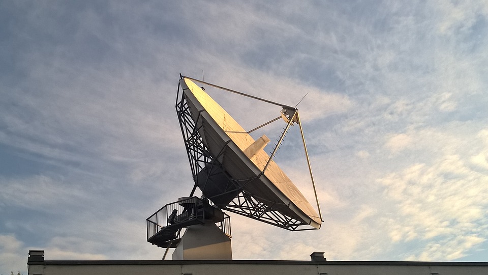
The satellite signal is reasonably well protected from interference, however, a stroke of lightning on a piece of ground equipment can make it disabled. The main measures to improve the quality and reliability of communications will be the grounding and protection of a satellite antenna against lightning.
ZANDZ Technical Center has provided electrolytic grounding electrodes for earthing a satellite antenna, which suit well for use in permafrost soils in Yakutia.
The rack on the radiolucent dome is used as an interception rod, while the armored cable from the rack is routed to the ground electrode. The solution for lightning protection of a satellite antenna is provided by the designer of the antenna station structure.
Find out more from our newswire texts.
Task
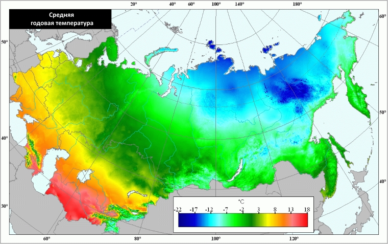
Calculate the grounding of a satellite antenna in Yakutia.
Solution
Solutions for grounding a satellite antenna were made in accordance with the 7th edition of the Electrical Installation Code.
Satellite antenna grounding system description
A set of measures to ensure the necessary requirements for the grounding arrangement is represented by the following solutions:
- To achieve the standardized resistance of the grounding arrangement, it is proposed to use ZANDZ ZZ-100-102 electrolytic grounding, specially designed for use in stony and permafrost soils.
- There was made an installation of 4 sets of electrolytic grounding ZANDZ ZZ-100-102. All sets were placed at a distance of 6 meters with a parallel arrangement to achieve the acceptable utilization rate and an optimal volume of electrolyte distribution in the soil.
- Electrolytic grounding sets are combined with a horizontal electrode from a corrosion-resistant copper-clad steel strip with a cross-section of 4x30 mm, and laying depth 0.5 m;
- Because of the formation of a talik zone in the oval form 3x6 meters in size, the electrodes must be placed at an appropriate distance off the foundations of buildings and other engineering structures.

Ю-С - S-N
Антенный пост АП-3,7-ПП - Antenna station AP-3,7-PP
Радиопрозрачное укрытие - Radio transparent shelter
Площадка для обслуживания РПУ (радиоприемного устройства) - Platform for maintenance of the radio receiving equipment (radio receiver)
Условные обозначения - Conventional symbols
Горизонтальный заземлитель - Horizontal ground electrode
Комплект электролитического заземления ZZ-100-102 - Electrolytic grounding set ZZ-100-102
Зажим для подключения проводника (ZZ-005-064) - Main conductor connection terminal (ZZ-005-064)
Кабельная эстакада - Overhead cable tray system
Стойка монтажная - Mounting rack
РПУ (радиоприемное устройство) - Radio receiving equipment (radio receiver)
Кабельные лотки 100х100мм в вентилируемом подполье под зданием - Cable trays 100x100mm in a ventilated underground under a building
Разгрузочная рама - Unloading frame
Кабельные линии - Cable lines
Верх ростверка - Foundation grille top part
Picture 1. Satellite antenna earthing layout
Calculation of resistance of the grounding arrangement
The predicted soil resistivity is taken to be 1000 Ohm ∙ m.
Warning. In case the Customer provided erroneous and limited soil data, the above calculation of a grounding arrangement is considered incorrect. If the soil resistivity differs from the calculated one, it is necessary to perform computations with a real value. If the normalized impedance of the grounding arrangement is exceeded, there must be introduced the design corrections.
The resistance set ZZ-100-102:
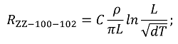
where C – is a nondimensional factor, describing the electrolyte content in the surrounding soil;
ρ – is a soil resistivity, Ohm · m;
L – is the ground electrode length, m;
d – is a diameter of the ground electrode, m;
T – is a embedment – a distance from the surface of the earth to the ground electrode system, m.
Horizontal electrode resistance:
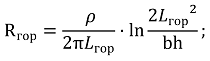
where – is the soil resistivity, Ohm · m;
b – strip width of a horizontal electrode, m;
h – is a laying depth of the horizontal mesh, m;
Lгор – is a horizontal electrode length, m
Electrical impedance of the grounding arrangement:
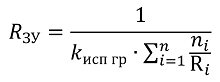
where n – is the number of sets;
kисп – is utilization rate.
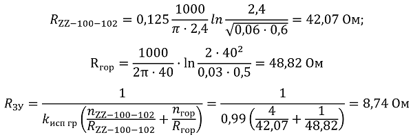
The design resistance of the grounding arrangement is 8.74 ohms.
Satellite antenna grounding accessories
| № | Part number | Description | Quantity, pcs. |
| Grounding arrangement | |||
| 1. | ZZ-100-102 | ZANDZ Electrolytic Grounding Set (horizontal; 3 meters length) | 4 |
| 2. | GL-11075-50 | Copper-clad strip GALMAR (30*4 mm/ S 120 mm²; 50-meter strip bundle) | 1 |
| 3. | ZZ-005-064 | Conductor connection terminal ZANDZ (up to 40 mm) | 12 |
| 4. | ZZ-007-030 | ZANDZ Waterproofing tape | 3 |
Do you have any questions about satellite antenna grounding? Please, contact the ZANDZ Technical Center!
Related Articles: