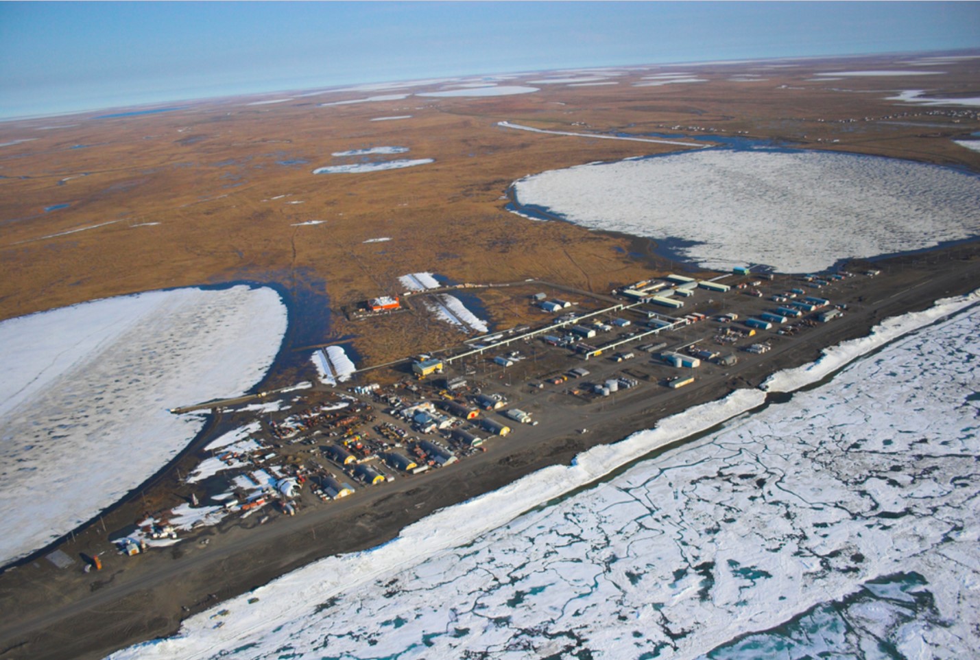
Aviation is one of the safest means of transportation. Control over the takeoffs is carried out from supervisory units, which are located in an open area not far from the runway. There can be antennas, radars and other equipment on these facilities that is why, it is necessary to provide protection against direct lightning strike and perform grounding for a proper operation of electronic equipment! Otherwise, the lack of safety measures may lead to a technical malfunction of the equipment and the loss of communication with aircrafts. In our technical center received a request for a calculation of solutions for lightning protection and grounding for a supervisory unit in Saransk airport. Our technical experts offered a solution, which we are sharing with you.
Task:
It is necessary to perform lightning protection and grounding.
Object: Runway supervisory unit (RSU-2), located in the territory of Saransk airport.
Outside dimensions:
- length: 15 m;
- width: 6.7 m;
- Height: 5.7 m.
There are 9 antennas 2 m each placed on the facility.
Power supply - 380 V.
Type of soil: sandy clay (soil resistivity - 150 Ohm * m).
Supervisory units refer to "special objects with limited risk" from points of view of lightning protection in accordance with the IS and category 3 according to the AD. The required reliability of the system adopted by the project 0.95 (according to category 2).
According to EIC-7, p. 1.7.103. The total spreading resistance of the ground electrodes (including natural) of all repeated groundings of the PEN conductor of each overhead line at any time of the year should not exceed 10 ohms at line voltage of 380 V of the three-phase power supply or 220 V of a single-phase power source.
The complex of measures to ensure necessary requirements for the lightning protection system of RSU-2 is represented by the following solutions:
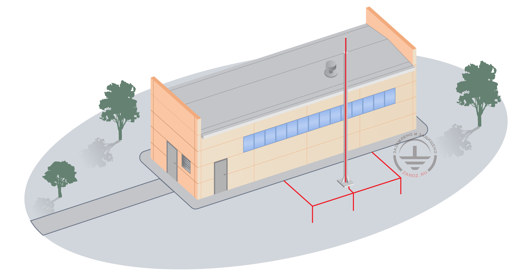
- Installation of two air terminal-mast height 6 m high at the edges of the roof (1.5 m from the edge). Organize 2 down conductors from each lightning rod using copper-bonded steel wire D = 8 mm and connect all the antennas (9 pcs.), stairs and metal objects / parts on the roof to down conductors (see. Fig.1).
- Installation of the grounding device, which consists of four vertical electrodes D = 14 mm, 4,5 m long, united by the horizontal electrode (copper-bonded tape 30x4 mm). The distance from the electrode to the walls of the building is not less than 1 m, the distance between the electrodes is not less than 5 m, penetration is 0.5 - 0.7 meters.
Calculation of the grounding device resistance:
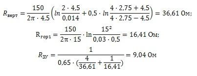
The design resistance of the grounding device is 9.04 Ohms, which is less than the required one of 10 Ohm.
Results of calculation of the protection zones in accordance with the IS:
Air terminal-mast №1, 2 (GL-21125): h = 11,7 m;
Height of the cone according to the IS chart. 3.4: h0 = 0,8 · h = 9,36 m;
The radius of the cone according to the IS chart. 3.4: r0 = 0,8 · h = 9,36 m;
The radius of the horizontal cross-section rx at the height of hx = 5.7 m for the protection zone of required security is determined by:
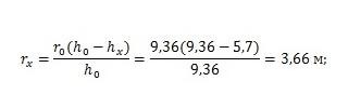
The results of the calculation performed by the software, developed by JSC "Energy Institute to the name of G. M. Krzizhanovsky"( JSC "ENIN"):
The density of lightning strikes into the ground - 6 strikes / sq. km per year;
The total number of strikes into the system in: 0.029 (once in 207 years);
The total number of breakthroughs: 0.0013.
System reliability: 0.955.
Probability of a breakthrough in all the system objects: 0,045 (once in 735 years).
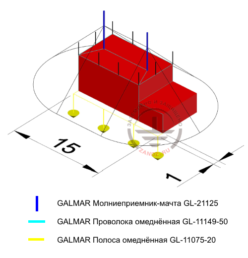
Figure 1 - Arrangement of lightning protection and grounding equipment. Protection zone
Молниеприемник мачта – air-terminal mast
Проволока омедненная – copper bonded wire
Полоса омедненная – copper bonded tape
The list of equipment and required materials:

.jpg)


.jpg)
.jpg)
.jpg)
.jpg)
.jpg)
.jpg)
.jpg)
Need help with calculation of grounding and lightning protection? Please contact our Technical center ZANDZ.com!
See also:
- Grounding. What is it and how to make it?
- Book: "Questions of practical lightning protection"
- Ready modular grounding kits
Related Articles: