According to RD 34.21.122-87 "Instructions for lightning protection of buildings and structures" (hereinafter RD), the probability of a lightning breakthrough is a parameter characterizing the failure of a lightning rod as a protective device. It equals the number of lightning discharges into the protected structure divided by the total number of lightning discharges into the lightning rod and the protected structure. The standard degrees of reliability are 0.95 and 0.99.
In September, the ZANDZ Technical Center received a request for lightning protection calculations with the following requirements: lightning protection zone A, reliability 0.99, the structure must be made of freestanding tower interception rods. Given that the item is a traction substation, the strict requirements are entirely appropriate. The ZANDZ Technical Center performed the calculations according to SO 153-34.21.122-2003 "Guidelines for making the lightning protection of buildings, structures and industrial infrastructure" (hereinafter SO), see Figure 1.
Lightning protection calculations
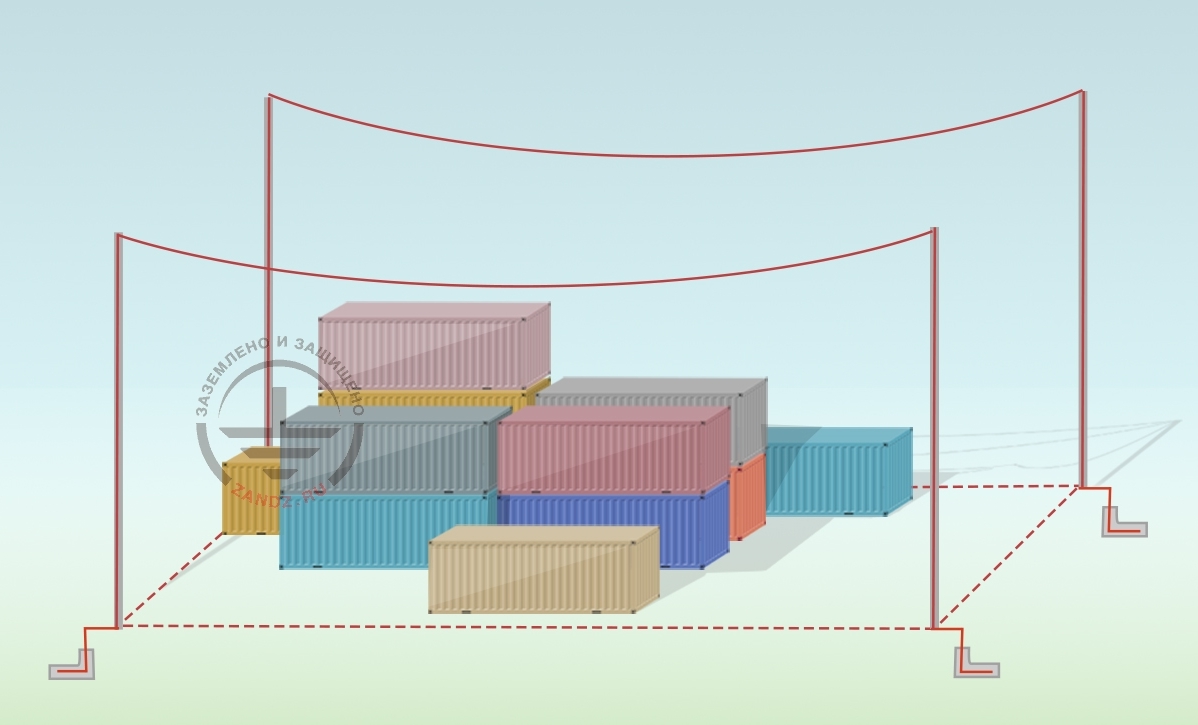
Protection of buildings against lightning strikes is provided by using lightning arresters. Lightning arrester is a device that is elevated over the protected facility through which the lightning current goes into the ground bypassing the protected facility. It consists of a lightning rod arrester that accepts the lightning discharge directly, a current collector, and a ground terminal.
The set of arrangements ensuring compliance with the lightning protection requirements is based on the following solutions:
- installation of 4 free-standing lightning protection systems with a height of 26 m. see Figure No. 2;
- the protective zone radius and height at which the protection zone A is built according to RD are shown in Figures No. 3 and No. 4.
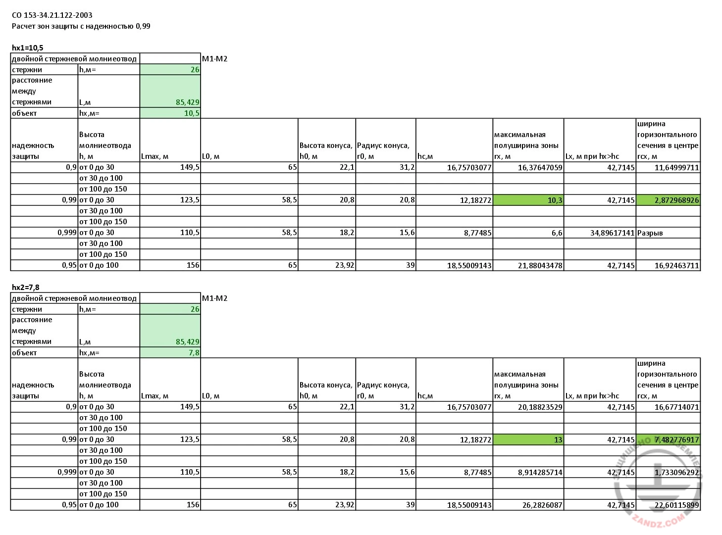
Figure 1. Calculations of protective zone with a reliability of 0.99. View the calculations on a separate page
| СО 153-34.21.122-2003 | SO 153-34.21.122-2003 |
| Расчет зон защиты с надежностью 0,99 | Calculation of protection zones ith the reliability of 0.99 |
| двойной стержневой молниеотвод | dual lightning rod arrester |
| стержни | rods |
| расстояние между стержнями | space between rods |
| Объект | Structure |
| надежность защиты | protection reliability |
| Высота молниеотвода h, м | lightning rod arrester’s height h, m |
| Lmax, м | Lmax, m |
| Высота конуса, h0, м | сone height, h0, m |
| Радиус конуса, r0, м | сone radius, r0, m |
| hc, м | hc, m |
| максимальная полуширина зоны rх, м | maximum half-width of zone rx, m |
| Lx, м при hx>hc | Lx, m at hx>hc |
| ширина горизонтального сечения в центре rcx, м | horizontal cross-section width in the center, rcx, m |
| Разрыв | Gap |

Figure 2. Vertical lightning protection system
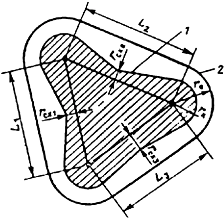
Figure 3. The protective zone of the multiple lightning rod arrester. It is defined as the protective zone of paired adjacent lightning rod arresters with a height of h ≤ 150 m
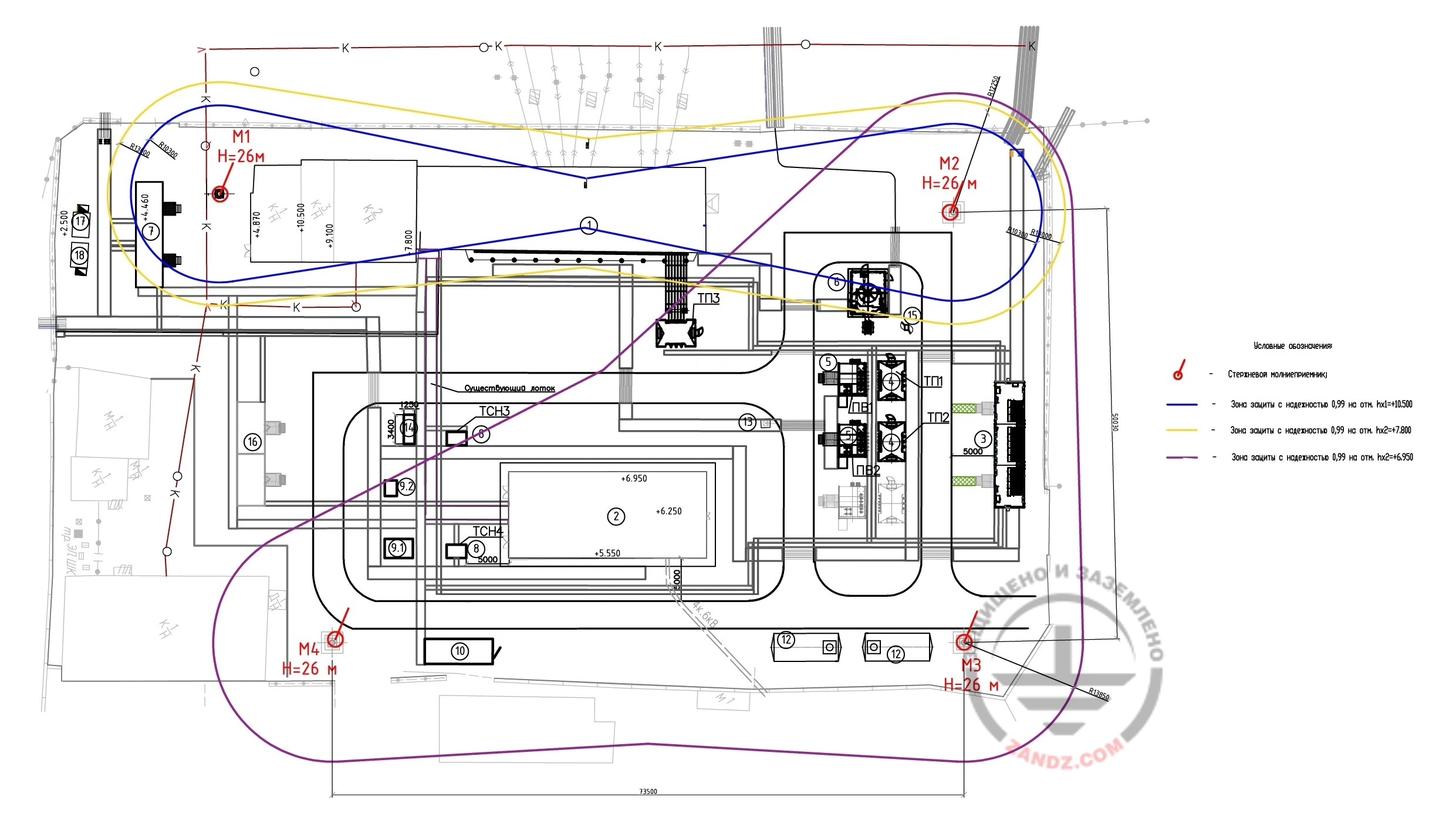
Figure 4. Location of lightning protection systems, protective zones. View the diagram on a separate page
Grounding calculations
According to clause 2.5 of RD, the distance from the ground terminal of free-standing lightning protection systems to the cable channels should be equal to Sb + 2 m. Sв is defined in clause 2.3 and is 3 m in the soil with a resistivity of up to 100 ohms * m, and in the soil from 100 to 1000 ohms * m is 4 m if an artificial ground terminal from clause 2.2 is used, or calculated by the formula. The customer has reserved the choice of the location of the ground terminals, so they are not shown in Figure No. 3.
A set of measures to ensure the necessary requirements for the grounding arrangement for each lightning protection systems is represented by the following solutions:
- installation of a grounding arrangement consisting of a horizontal electrode (galvanized steel strip with a cross section of 4x40 mm), a depth of 0.5 meters and 3 vertical electrodes (pins made of galvanized steel with a diameter of 16 mm) with a length of 3 m each;
- the vertical and horizontal electrodes are connected to each other using ZZ-202-022 clamps;
- the connection points of the lightning arrester with the withdrawal of the galvanized strip from the ground are carried out using control clamps ZZ-202-023.
Table 1. List of required materials
| Item No. | Fig. | Part number | Product | Qty |
| Lightning protection system | ||||
| 1 | 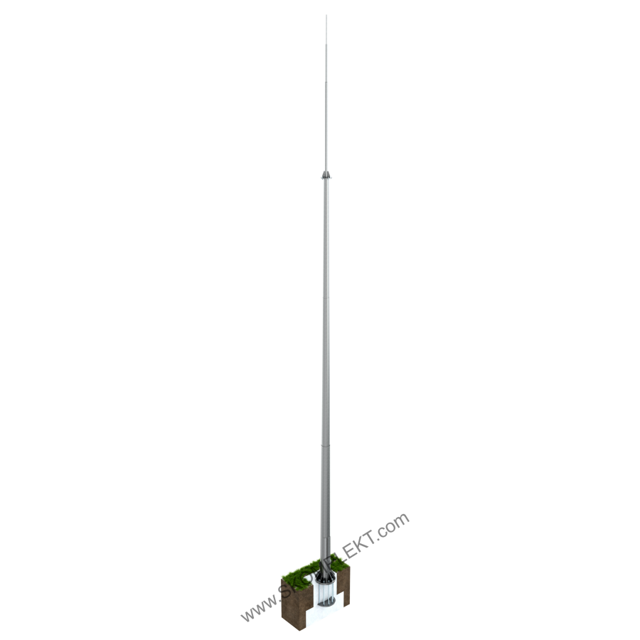 |
ZZ-201-026 | Vertical lightning protection system 26 m (galvanized steel; with parts embedded under the foundation) | 4 |
| Grounding arrangement | ||||
| 2 | 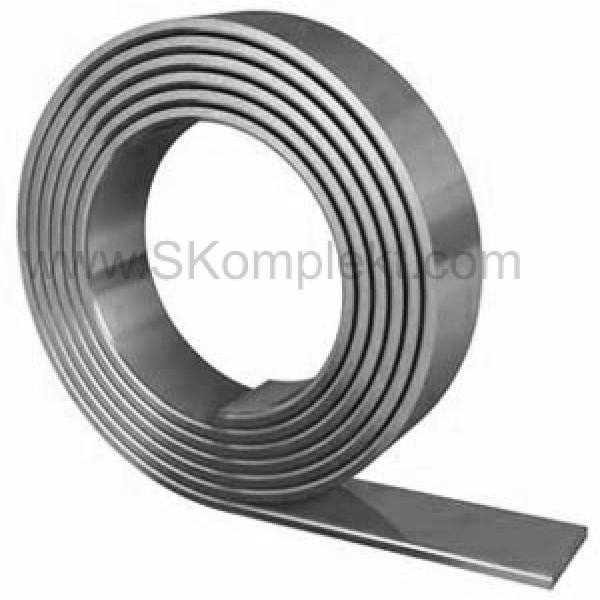 |
ZZ-502-404-38 | ZANDZ Steel galvanized bar (40*4 mm; 38.5 m bundle) | 2 |
| 3 | 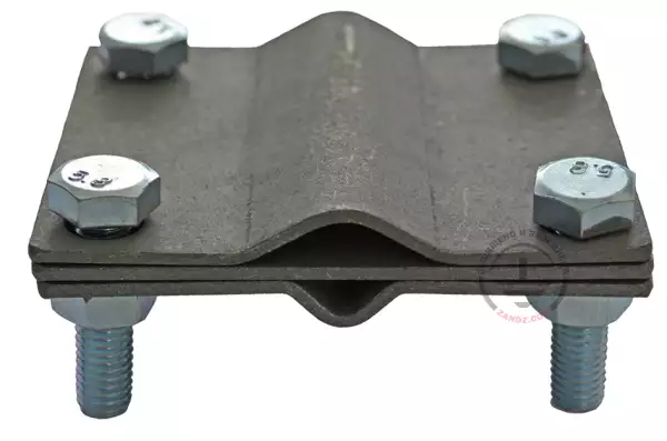 |
ZZ-202-022 | ZANDZ ZZ-202-022 - Clamp for round conductor and strip (D14-20 mm; up to 40x6; galvanized steel) | 12 |
| 4 | 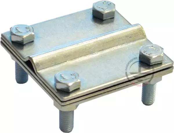 |
ZZ-202-023 | ZANDZ ZZ-202-023 - Clamp for round conductor and strip (D6-10 mm; up to 50x6; galvanized steel) | 4 |
| 5 |  |
ZZ-001-255 | ZANDZ Threaded galvanized grounding rod (D16; 1.5 m; M16) | 24 |
| 6 |  |
ZZ-002-251 | ZANDZ Threaded galvanized connection coupling (M16) | 14 |
| 7 |  |
ZZ-003-250 | ZANDZ Termination for galvanized grounding rods (M16; galvanized steel) | 12 |
| 8 |  |
ZZ-004-250 | ZANDZ Guide head for jackhammer attachment (M16; galvanized steel) | 6 |
| 9 |  |
ZZ-006-000 | ZANDZ Conductive grease | 2 |
| 10 |  |
ZZ-007-030 | ZANDZ Waterproof tape | 4 |
| 11 |  |
ZZ-008-000 | ZANDZ Attachment to the hammer (SDS max) | 1 |
Do you have any questions about lightning protection for the cadet school or other facilities? Please, contact the ZANDZ Technical Center!
Related Articles:
