According to SO 153-34.21.122-2003 «"Guidelines for Arrangement of Lightning Protection of Buildings, Structures, and Industrial Utilities" (hereinafter, SO), plants, including those using, in their production, flammable materials, are classified as "Conventional". It means that, in case of a lightning strike,
"additional effects depending on production conditions: minor damage to significant damage due to product loss" may appear.
According to RD 34.21.122-87 "Guidelines for Arrangement of Lightning Protection of Buildings and Structures" (hereinafter, RD), plants are classified as lightning protection Category 3 facilities. This provides for the use of standalone rod or wire lightning arresters, or arresters installed on the roof to ensure the required protection zone. However, when fire-proof or hardly flammable thermal insulation and waterproofing are used, lightning rods may not be installed.
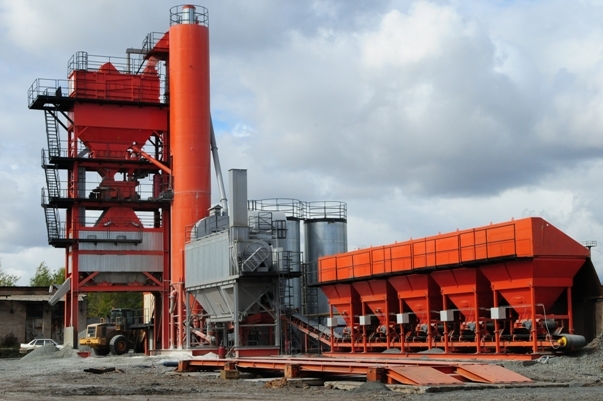
Let's consider the calculation of the lightning protection and grounding for the plant using a real-life example. This year, the ZANDZ.com Technical Center has received a request to calculate the lightning protection for an asphalt and concrete plant in the Moscow Region. The ZANDZ.com technical specialists have performed the calculation according to the requirements of the EIC, Rev. 7 Chapter 1.7, SO and RD.
Lightning protection calculation
Protection of buildings against lightning strikes is provided by using lightning arresters. Lightning arrester is a device that is elevated over the protected facility through which the lightning current goes into the ground bypassing the protected facility. It consists of a lightning rod that directly accepts the discharge of a lightning , a current collector, and a ground terminal.
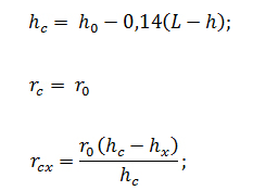
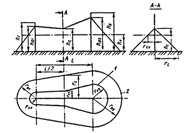
Calculation of protection zones of repeated lightning arresters is performed according to items 2.2 and 3 of Appendix 3 to RD 34.21.122-87 for the zone B. The protection zone of the repeated lightning arresters is defined as a protection zone of the pairs of adjacent lightning arresters. Taking into account that, in this case, the distance between the lightning arresters is greater than the height but less than six heights of lightning rods, we can use the respective set of formulas:
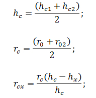
Since lightning rods have different heights, we will use the following formulas to calculate sizes of internal area of protection zones:
Arrangement of Lightning Protection of Main Workshop of Plant and Tank
- Lightning protection of the plant workshop and tank (lower right in the lightning protection and grounding diagram) is provided using artificial lightning rods, i.e. building structures according to item 2.11 of RD: "The installation of lightning rods or lightning grid is not required for the buildings and structures having metal frames if their roofs contain fire-proof or hardly flammable thermal insulation and waterproofing";
- according to items 1.6 and 2.12 of RD, metal building frame is used in case of the presence of continuous electrical coupling at connections of the structures and reinforced bars with lightning rods and ground terminals;
- according to items 1.8 and 2.13 of RD, reinforced foundation of the building is used as a ground terminal provided that continuous electrical coupling is ensured along its reinforced bar;
- the design of the grounding arrangement conforms to the item 1.7.55 of the EIC. Grounding arrangements for protective grounding and grounding for lightning discharges are common.
Arrangement of Lightning Protection for Other Structures at the Facility
A set of arrangements ensuring compliance with the lightning protection requirements is based on the following solutions:
- mounting of 6 x 7 m high lightning rods is carried out by attachment to the wall. It is taken into account that 1.5 m of the height of lightning rod is necessary for mounting;
- Installation of 6 x 4 m lightning rods on the wall. It is taken into account that 0.7 m of the height of lightning arrester are necessary for mounting.
- installation of 4 x 2 m lightning rods on the wall. It is taken into account that 0.7 m of the height of lightning arrester are necessary for mounting.
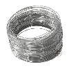
- Lightning rods are interconnected to arrange two current collectors using galvanized steel wire D = 8 mm from each lightning rod. The current collectors are attached (with mounting step 0.6-1 m):
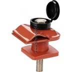
- connection and branching of current collectors are made using clamps GL-11551А.
The selection of the ground terminal structure as a combination of horizontal and vertical arrangements at the current collector locations is based on item 2.26 of RD 34.21.122-87 and item 3.2.3.2 of SO 153-34.21.122-2003.
A set of measures to ensure the necessary requirements to the grounding arrangement is represented by the following solutions:
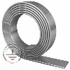
- mounting of grounding arrangements consisting of horizontal electrodes (galvanized steel strip with a cross-section 4 x 30 mm), depth of 0.5 meter, the distance to the wall is 1 m and 24 x 3 m vertical electrodes (rods made of copper-plated steel having diameter of 14 mm);
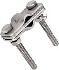
- interconnection of vertical and horizontal electrodes is carried out using clamp ZZ-005-064;
- current collector is connected to the output of the galvanized ground strip using control clamp GL-11562A;
- Grounding arrangements for protective grounding and grounding for lightning discharges are common. Any grounding arrangement may be used as a protective ground terminal.
Grounding and Lightning Protection Diagram
The location of the elements of the lightning protection system and the grounding arrangement is shown in a drawing in a separate file. The depicted protection area corresponds to area B, constructed as per Appendix 3 to RD.
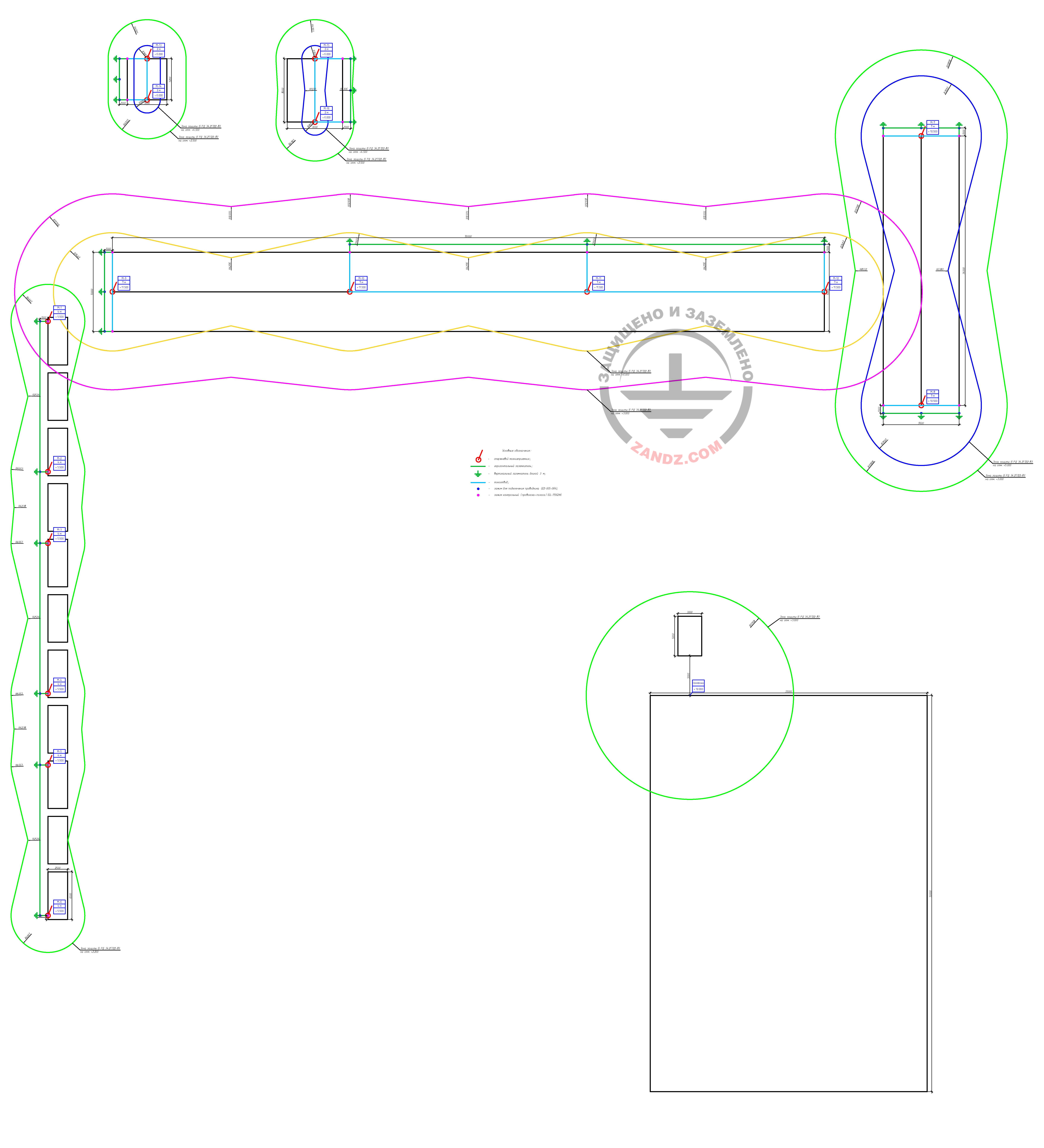
Layout of lightning protection system and grounding arrangement elements of the asphalt and concrete plant (click here to view full image)
Table 1. List of required materials.


Do you have any questions about lightning protection for the cadet school or other facilities? Please, contact the ZANDZ Technical Center!
Related Articles: