Lightning often brings a lot of trouble when it gets into some kind of building or structure, because the damage can be very different.
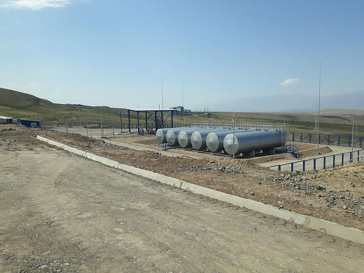
ZANDZ Technical Center received a request for the calculation of a lightning protection system for a pipe with ammonia emissions at a site with receivers. Several solutions to this problem were prepared, let’s consider one of them.
Initial data:
- Object plan;
- Pipe height - 11 m;
- Soil resistivity – 36 Ohm*m.
The measures were performed in accordance with:
- EIC 7-th ed.;
- IS 153-34.21.122-2003 «Instruction to lightning protection of buildings, structures and industrial communications» (hereinafter IS);
- AD 34.21.122-87 «Instruction on arrangement of lightning protection for buildings and structures» (hereinafter AD).
The object refers to the "special, representing danger to the immediate environment", in accordance with IS and to the 2nd category, according to AD. The necessary reliability of the lightning protection system should be at least 0.95.
A set of measures to ensure the necessary requirements for a lightning protection system of a pipe with ammonia emissions at a site with receivers is represented by the following solutions:
- Lightning protection of the pipe is carried out using an air terminal mast 25 m high (ZZ-201-025).
- The building is protected by a natural lightning conductor (metal roof (girders)).
- In accordance with AD 34.21.122-87, p. 2.18, breathing valves should be protected from direct lightning strikes and the space above them limited by a cylinder h = 2.5 m with a radius of 5 m.
- The grounding device is carried out in accordance with AD 34.21.122-87, п.2.13.
- Copper-coated steel electrodes 3 m long are used as a vertical grounding electrode. A copper-plated steel tape with a cross-section of 30x4 mm, which unites all vertical electrodes, is used as a horizontal grounding electrode. The distance to the foundation of the facility is not less than 1 m. The depth of the tape burying is 0.5 - 0.7 m.
- According to EIC-7 ed., p.1.7.55 - Grounding devices for protective grounding of electrical installations of buildings and structures and lightning protection of the 2nd and 3rd categories of these buildings and structures, as a rule, should be common.
- If there are reinforced concrete structures, they must be connected to the grounding device.
- Connection to the grounding device is carried out using ZZ-005-064 clamps.
- density of lightning strikes into the ground – 4strikes / sq km per year;
- the total number of strikes into the system is 0.08 (once every 12 years);
- the total number of breakthroughs (strikes directly into an object bypassing lightning rods) - 0.0019 (every 526 years);
- system reliability - 0.976.
Calculation of the grounding device resistance:
Resistance of the vertical electrode:
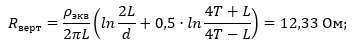
where ρэкв – equivalent soil resistivity - 36 Ohm·m;
L – vertical electrode length - 3 m;
d – vertical electrode diameter - 0,014 m;
T – burial – distance from the ground surface to the ground electrode - 2 m;
where t – burial of the electrode top - 0,5 m
Horizontal electrode resistance:
where ρ – soil resistivity - 36 Ohm·m;
b – horizontal electrode width - 0,03 m;
h – horizontal conductor laying depth - 0,5 m;
Lгор– horizontal electrode length - 71 m.
Grounding device impendance:
where n – number of kits, vertical ground electrodes – 4 pieces, horizontal ground electrode – 1 piece ;
Kисп – utilization ratio, 0,75;
The rated resistance of the grounding device is 1.08 Ohm.
The equipment location and protection zone are shown in Figure 1.
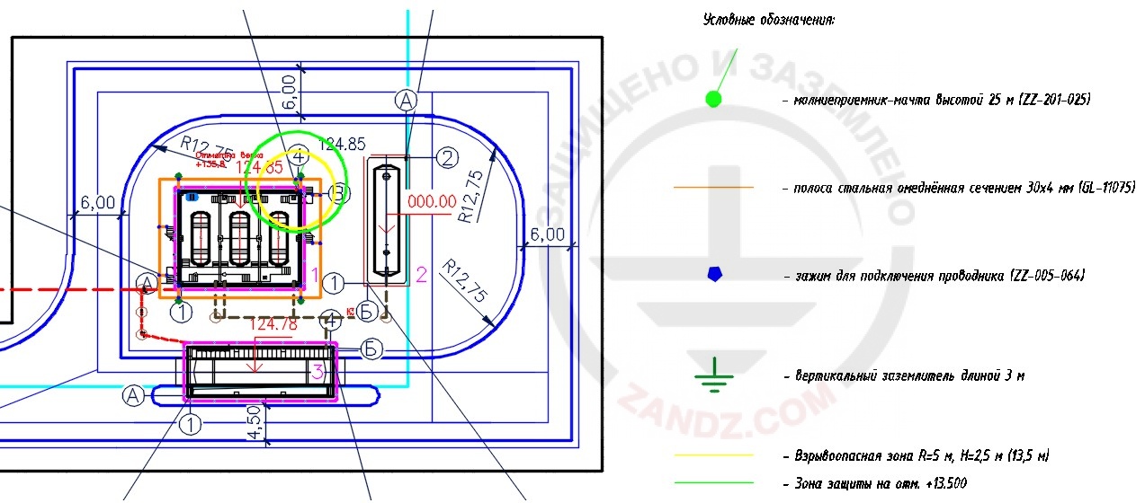
- Условные обозначения – Type Codes
- Молниеприемник – мачта высотой 25 м – Air-terminal mast 25 m high
- Полоса стальная омедненная сечением 30*4 мм – Copper-bonded steel tape with the cross-section of 30*4mm
- Зажим для подключения проводника – Clamp for connecting conductor
- Вертикальный заземлитель длиной 3 м – vertical ground electrode 3 m long
- Взрывоопасная зона – Explosive zone
- Зона защиты на – Protection zone on
Figure 1 – Equipment location.
The list of equipment and required materials is given in table 1.
Table1 – List of materials need.
|
№ |
Product item |
Name |
Q-ty, pc. |
Weight, unit, kg |
Note |
|
1. |
ZZ-201-025 |
ZANDZ Air terminal 25 m vertical (galvanized steel; with embedded details for foundation) |
1 |
|
|
|
2. |
GL-11075-50 |
GALMAR copper-bonded tape (30 * 4 mm / S 120 mm²; coil of 50 meters) |
2 |
0,98 |
In coils. Weight is indicated for 1 m |
|
3. |
ZZ-001-065 |
ZANDZ Copper-bonded threaded grounding pin (D14; 1.5 m) |
8 |
2,00 |
|
|
4. |
ZZ-002-061 |
ZANDZ Threaded connecting coupler |
5 |
0,08 |
|
|
5. |
ZZ-003-061 |
ZANDZ Starting tip |
4 |
0,07 |
|
|
6. |
ZZ-004-060 |
ZANDZ Driving head for a breaker hammer |
2 |
0,09 |
|
|
7. |
ZZ-005-064 |
ZANDZ Clamp for connecting conductor (up to 40 mm) |
21 |
0,16 |
|
|
8. |
ZZ-006-000 |
ZANDZ Conductive grease |
1 |
1,10 |
|
|
9. |
ZZ-007-030 |
ZANDZ Hydro insulation tape |
7 |
0,40 |
|
|
10. |
ZZ-008-000 |
ZANDZ Head for a breaker hammer (SDS max) |
1 |
0,50 |
|
Do you have any questions about lightning protection and grounding of pipes with ammonia emissions at the site with receivers? Contact ZANDZ Technical Center!
Related Articles: