Webinar text. Page 2
Basic SDP parameters
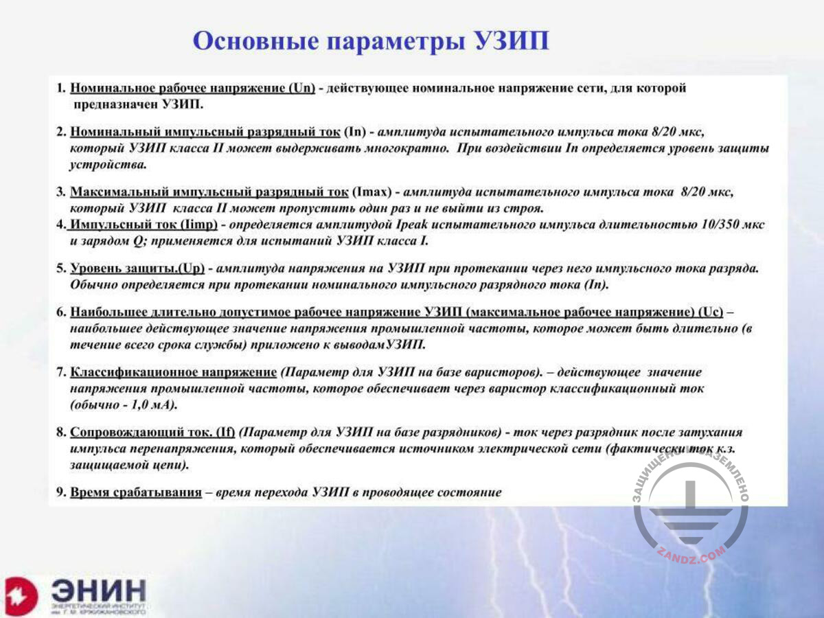
Основные параметры УЗИП
1. Номинальное рабочее напряжение (Un) – действующее номинальное напряжение сети, для которой предназначен УЗИП.
2. Номинальный импульсный разрядный ток (In) – амплитуда испытательного импульса тока 8/20 мкс, который УЗИП класса II моет выдерживать многократно. При воздействии In определяется уровень защиты устройства.
3. Максимальный импульсный разрядный ток (Imax) – амплитуда испытательного импульса тока 8/20 мкс, который УЗИП класса II может пропустить один раз и не выйти из строя.
4. Импульсный ток (Iimp) – определяется амплитудой Ipeak испытательного импульса длительностью 10/350 мкс и зарядом Q; применяется для испытаний УЗИП класса I.
5. Уровень защиты (Up) – амплитуда напряжения на УЗИП при протекании через него импульсного тока разряда. Обычно определяется при протекании номинального импульсного разрядного тока (In).
6. Наибольшее длительно допустимое рабочее напряжение УЗИП (максимальное рабочее напряжение) (Uc) – наибольшее действующее значение напряжения промышленной частоты, которое может быть длительно (в течение всего срока службы) приложено к выводам УЗИП.
7. Классификационное напряжение (параметр для УЗИП на базе варисторов) – действующее значение напряжения промышленной частоты, которое обеспечивает через варистор классификационный ток (обычно – 1,0 мА).
8. Сопровождающий ток (If) (Параметр для УЗИП на базе разрядников) – ток через разрядник после затухания импульса перенапряжения, который обеспечивается источником электрической сети (фактически ток к.з. защищаемой цепи).
9. Время срабатывания – время перехода УЗИП в проводящее состояние.
Basic SDP parameters
1. Nominal operational voltage (Un) is the effective nominal voltage of the grid, for which the SDP is intended.
2. Nominal pulse discharge current (In) is the amplitude of the test current pulse 8/20 mcs, which may repeatedly withstood by the Class II SDPs. Upon exposure of In, the device protection level is determined.
3. Maximum pulse discharge current (Imax) is the amplitude of the test current pulse 8/20 mcs, which may pass through the Class II SDPs once without its failure.
4. Pulse current (Iimp) is determined by the test pulse amplitude Ipeak with the duration of 10/350 mcs and charge Q; it is used for testing the Class I SDPs.
5. Protection level (Up) is the amplitude of the voltage at SDP upon the discharge pulse current flowing therethrough. It is usually determined upon the nominal pulse discharge current (In) flowing.
6. Longest possible operating voltage of SDP (maximum operating voltage) (Uc) is the maximum effective voltage of the industrial frequency that may be applied to the SDP terminals for a long time.
7. Classification voltage (parameter for the variable resistor-based SDP) is the effective voltage of industrial frequency that provides the classification current (usually, 1.0 mA) flowing through the variable resistor.
8. Follow current (If) (parameter for the arrester-based SDPs) is the current flowing through the arrester after the surge pulse fade-away that is provided by an electrical grid source (in fact, it is the short circuit current of the protected circuit).
9. Response time is the time of the SDP transition to the conductive state.
We have already mentioned the SDP parameters, but I want to tell you the following thing. What is the main indicator of any SDP? First, it is a nominal voltage, with which this SDP may operate; it is the grid’s nominal voltage. The second indicator is the protection voltage it provides. The third indicator is its speed of response: for how many nano or microseconds it triggers. And all other indicators define the current that the SDP of this type may pass through itself. This may be either a pulse 10/350 mcs current, if these are powerful SDPs. This may be the 8/20 mcs current. These are the SDPs that are designed for the operation in the circuits that the lightning current does not enter. I want to tell you the following things about these indicators: 10/350 mcs current; it is rated as an indicator of the first component of the lightning current. Actually, it is a formality that was adopted in the international scale to be able to compare SDPs of different companies in terms of their capacity. Actually, the lightning current does not necessarily have a 10 mcs front. The first lightning current component has got a front of 1 mcs or 2 mcs or even 5 mcs, and its tail duration may be different.
Choosing an SDP for a particular electrical circuit
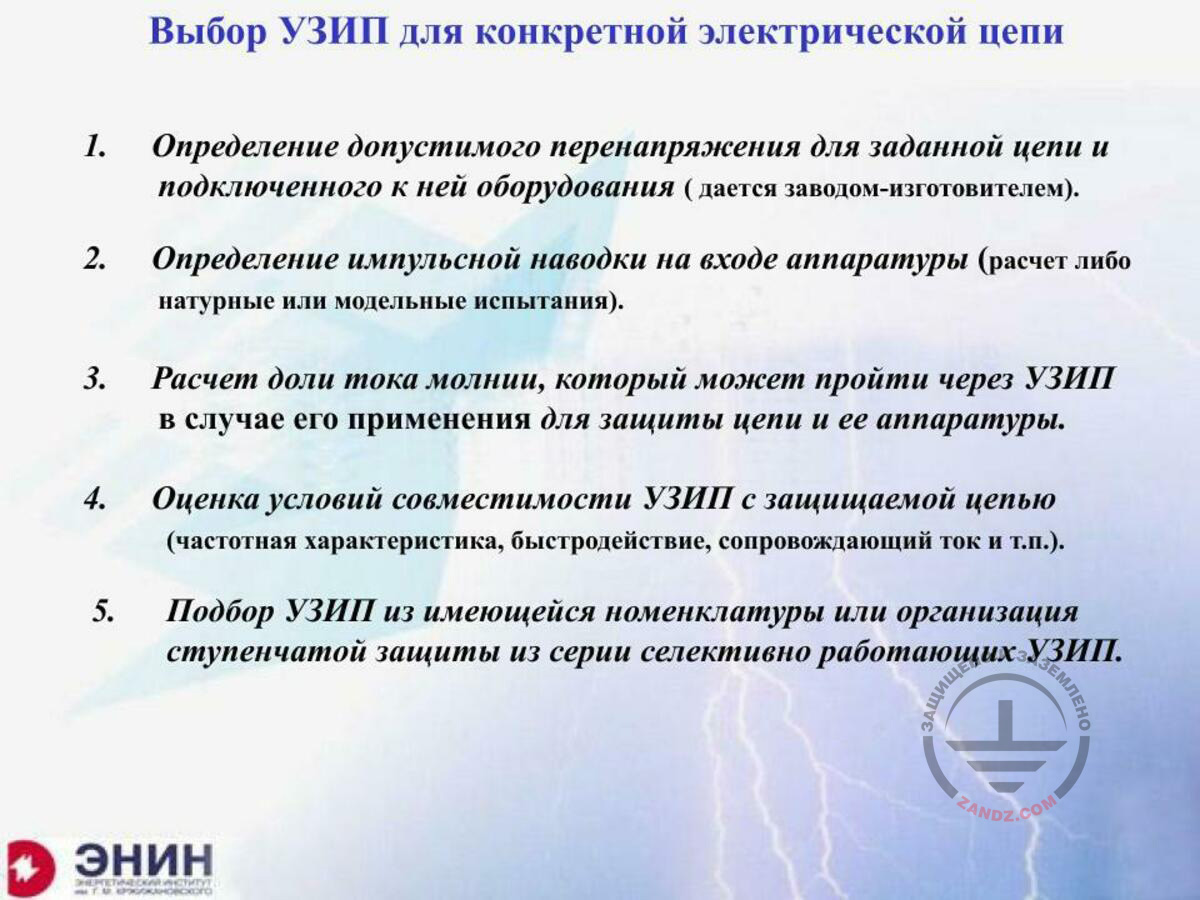
Выбор УЗИП для конкретной электрической цепи
1. Определение допустимого перенапряжения для заданной цепи и подключенного к ней оборудования (дается заводом-изготовителем).
2. Определение импульсной наводки на входе аппаратуры (расчет либо натурные или модельные испытания).
3. Расчет доли тока молнии, который может пройти через УЗИП в случае его применения для защиты цепи и ее аппаратуры.
4. Оценка условий совместимости УЗИП с защищаемой цепью (частотная характеристика, быстродействие, сопровождающий ток и т.п.).
5. Подбор УЗИП из имеющейся номенклатуры или организация ступенчатой защиты из серии селективно работающих УЗИП.
Choosing an SDP for a particular electrical circuit
1. Determining the allowable surge for the given circuit and the equipment connected thereto (provided by the manufacturer).
2. Determining the pulse interference at the equipment input (calculation or field or model tests).
3. Calculating the lightning current fraction, which may pass through the SDP in case of its application to protect the circuit or its equipment.
4. Evaluating the conditions for the SDP’s compatibility with the protected circuit (frequency characteristic, response time, follow current, etc.).
5. Choosing the SDP from the available product range or arranging the multi-stage protection from the series of selectively operating SDPs.
How should we choose an SDP? What do we have to start with when we need to choose an SDP? The first question to be solved is the question of electrical strength of the equipment to be protected. This is a strength of the electrical circuit, the strength of the equipment powered from this electrical circuit. And these data must be provided either by the customer or by the designer of this equipment. Or, if you do not have this data, you must determine it. And in order to do that, you must have a test bench. And it leads to a significant problem. The second point. You must determine, what surge will be in the electrical circuit you are going to protect. There are two points in this case: you may either perform tests by simulating the lightning current and measure your interference. This is a good way although it is hard to implement. And the second point is to use the calculations we discussed in the previous seminar, which allow evaluating your surge with a certain accuracy. Now, the third point. You need to determine at what current you need this SDP protection. What current will flow through the SDP when it is exposed to the storm surge? That is what we did in the previous webinar. When you have got three parameters, you may take the catalogue of the company you have chosen and look for the SDP there that will meet the three parameters. The protection voltage should be less than the one suitable for your equipment, and the currents flowing through the SDP should be less than those you will have there. And finally, you will need the third aspect, the speed of response. The speed of response should be the one your equipment needs. After the three requirements have been met, you will have the set of SDPs that are suitable for you. And one thing remains: among these SDPs, you must choose those that are suitable for the operating conditions. And these operating conditions include ambient temperature, ambient pressure, explosion hazard, fire safety issue, and generally it is the electrical safety for the personnel. Based on them, you may choose the SDPs.
SDP classification
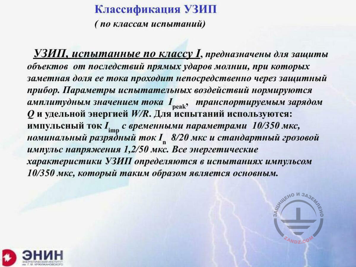
Классификация УЗИП
(по классам испытаний)
УЗИП, испытанные по классу I, предназначены для защиты объектов от последствий прямых ударов молнии, при которых заметная доля ее тока проходит непосредственно через защитный прибор. Параметры испытательных воздействий нормируются амплитудным значением тока Ipeak, транспортируемым зарядом Q и удельной энергией W/R. Для испытаний используются: импульсный тока Iimp с временными параметрами 10/350 мкс, номинальный разрядный ток In 8/20 мкс и стандартный грозовой импульс напряжения 1,2/50 мкс. Все энергетические характеристики УЗИП определяются в испытаниях импульсом 10/350 мкс, который таким образом является основным.
SDP classification
(according to test classes)
The SDPs tested in accordance with Class I are designed for the protection of facilities against the direct lightning strike effects, wherein a significant portion of its current passes directly through the protective device. The parameters of the test impacts are standardized by the amplitude current value Ipeak transported by charge Q and specific energy W/R. For testing, pulse current Iimp with time parameters 10/350 mcs, nominal discharge current In 8/20 mcs and standard storm voltage pulse 1.2/50 mcs are used. All energy characteristics of the SDPs are defined in the tests with the pulse 10/350 mcs, which is therefore major.
SDP classification according to Class II
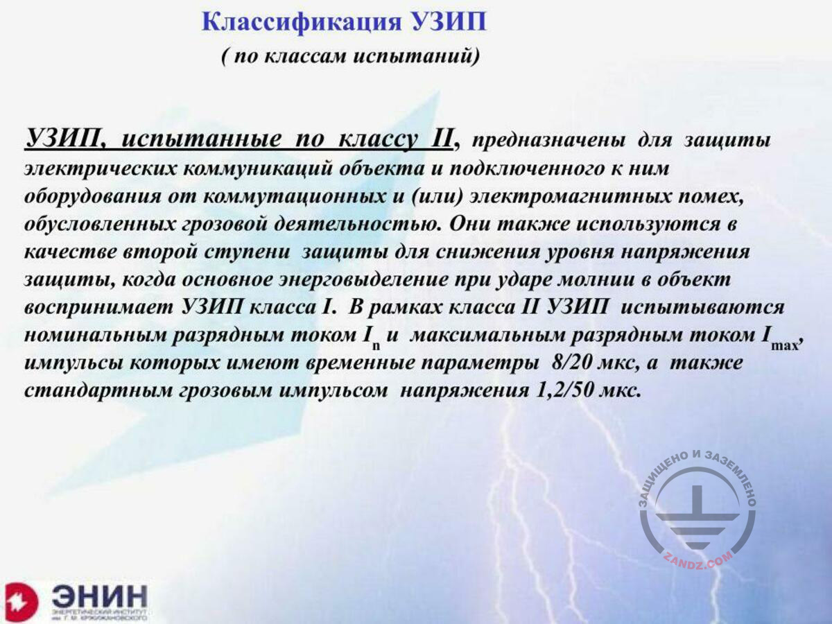
Классификация УЗИП
(по классам испытаний)
УЗИП, испытанные по классу II, предназначены для защиты электрических коммуникаций объекта и подключенного к ним оборудования от коммутационных и (или) электромагнитных помех, обусловленных грозовой деятельностью. Они также используются в качестве второй ступени защиты для снижения уровня напряжения защиты, когда основное энерговыделение при ударе молнии в объект воспринимает УЗИП класса I. В рамках класса II УЗИП испытываются номинальным разрядным током In и максимальным разрядным током Imax, импульсы которых имеют временные параметры 8/20 мкс, а также стандартным грозовым импульсом напряжения 1,2/50 мкс.
SDP classification
(according to the test classes)
The SDPs tested according to Class II are designed to protect the electrical utilities of a facility and the equipment connected thereto against commutation and/or electromagnetic interference caused by a storm. They are also used as the second protection stage to reduce the protection voltage, when the major energy release upon the lightning strike into the facility is accepted by the Class I SDPs. Within Class II, the SDPs are tested using the nominal discharge current In and the maximum discharge current Imax, the pulses of which have the time parameters 8/20 mcs, as well as the standard storm voltage pulse 1.2/50 mcs.
The SDPs tested according to Class II are generally designed for two cases. It is either intended for the protection of the electrical circuits wherein the lightning current does not go directly, and the surge occurs as a result of excitation of the electromotive force of magnetic induction. Therefore, such SDP is usually tested with the 8/20 mcs current and is tested for the voltage pulse of 1.2/50 mcs. What is the SDP intended for? Such SDPs are designed to: either protect the circuits where the lightning current does not get and where the induced interference exists, or it may be installed as a second stage after the Class I SDPs in the circuits, where the lightning current gets but where the reduced protection voltage is needed. Then, the major part of the current is taken by the SDPs tested according to Class I, followed by the Class II or even Class II SDPs operation.
SDP classification according to Class III
Классификация УЗИП
(по классам испытаний)
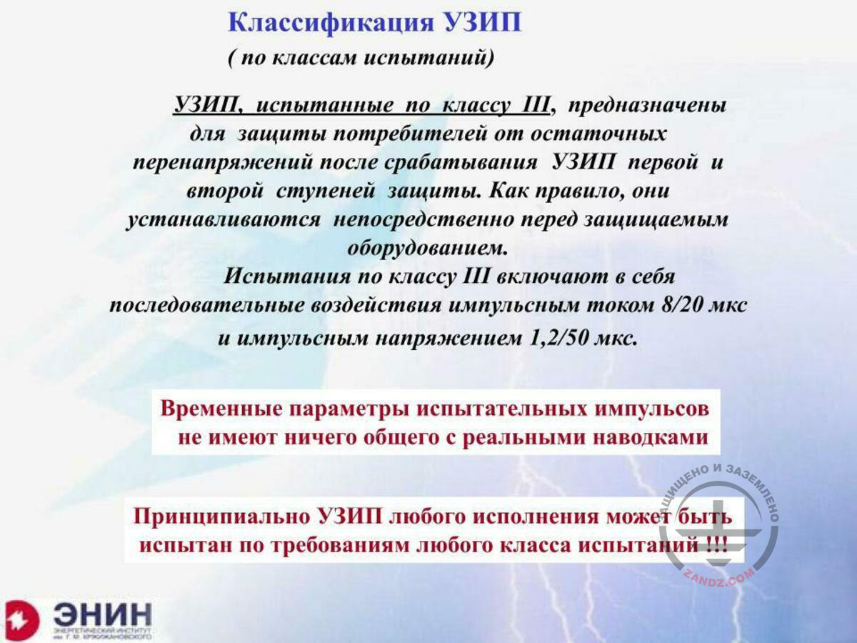
УЗИП, испытанные по классу III, предназначены для защиты потребителей от остаточных перенапряжений после срабатывания УЗИП первой и второй ступеней защиты. Как правило, они устанавливаются непосредственно перед защищаемым оборудованием. Испытания по классу III включают в себя последовательные воздействия импульсным током 8/20 мкс и импульсным напряжением 1,2/50 мкс.
Временные параметры испытательных импульсов не имеют ничего общего с реальными наводками
Принципиально УЗИП любого исполнения может быть испытан по требованиям любого класса испытаний!!!
SDP classification
(according to the test classes)
The SDPs tested in accordance with Class III are designed to protect consumers against the residual surges after the SDPs of the first and the second protection stages triggering. They are usually installed immediately before the protected equipment. The tests according to Class III include the sequential impacts of the pulse current 8/20 mcs and pulse voltage 1.2/50 mcs.
Time parameters of test pulses have nothing in common with the actual interference
In principle, the SDP of any design may be tested for the requirements of any test class!!!
The SDPs tested according to Class II are tested for the voltage 1.2/50 mcs and the current 8/20 mcs. You have to understand me correctly. These tests may be performed for any SDP. I have got an SDP based on the variable resistor washer. I would like and I can test it according to Class I. It appears that it will not withstand very high currents but it may be tested for these currents. And I can say that if it is exposed to the lightning current 10/350 mcs, it will withstand, for example, 3 kA. I can test any SDP according to any class and provide the test protocol on the basis of which I will make my choice.
Testing severity degree
Степень жесткости испытаний защищаемого оборудования
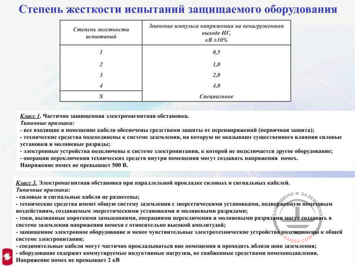
Степень жесткости испытаний
Значение импульса напряжения на ненагруженном выходе ИГ, кВ ±10%
Специальное
Класс 1. Частично защищенная электромагнитная обстановка.
Типичные признаки:
- все входящие в помещение кабели обеспечены средствами защиты от перенапряжений (первичная защита);
- технические средства подсоединены к системе заземления, на которую не оказывают существенного влияния силовые установки и молниевые разряды;
- электронные устройства подключены к системе электропитания, к которой не подключается другое оборудование;
- операции переключения технических средств внутри помещения могут создавать напряжения помех.
Напряжение помех не превышает 500 В.
Класс 3. Электромагнитная обстановка при параллельной прокладке силовых и сигнальных кабелей.
Типичные признаки:
- силовые и сигнальные кабели не разнесены;
- технические средства имеют общую систему заземления с энергетическими установками, подверженную помеховым воздействиям, создаваемым энергетическими установками и молниевыми разрядами;
- токи, вызванные короткими замыканиями, операциями переключения и молниевыми разрядами могут создавать в системе заземления напряжения помехи с относительно высокой амплитудой;
- защищенное электронное оборудование и менее чувствительные электротехнические устройства подсоединены к общей системе электропитания;
- соединительные кабели могут частично прокладываться вне помещения и проходить вблизи шин заземления;
- оборудование содержит коммутируемые индуктивные нагрузки, не снабженные средствами помехоподавления.
Напряжение помех не превышает 2 кВ.
Testing severity degree of the protected equipment
Testing severity degree
Voltage pulse at the unloaded input of the pulse generator, kV ±10%
Special
Class 1. Partially protected electromagnetic environment.
Typical features:
- all cables entering the room are provided with the surge protection means (primary protection);
- the technical means are connected to the earthing system that is not significantly exposed to the power units and lightning discharge effects;
- the electronic devices are connected to the power system, to which no other equipment is connected;
- operations for switching the technical means inside the room may create the interference voltage.
The interference voltage does not exceed 500 V.
Class 3. Electromagnetic environment with the parallel layout of the power and signal cables.
Typical features:
- power and signal cables are not spaced;
- the technical means have got an earthing system that is common with the energy units and that is exposed to the interference generated by the energy units and lightning discharges;
- the currents caused by the short circuits, switching operations and lightning discharges may create the interference voltages with a relatively high amplitude in the earthing system;
- protected electronic equipment and less sensitive electrotechnical devices connected to the general power system;
- connecting cables may be partially laid outside the room and be located near the earthing buses;
- the equipment contains the switching inductive loads, which are not provided by the noise suppression means.
Interference voltage does not exceed 2 kV.
And now, the second point is as follows. The point is that it is not enough to have SDP tests, you need to have the tests for the protected equipment. To protect the equipment, several testing severity degrees are available. I can test the equipment for severity Class 1, where the voltage I use for it will not be more than 0.5 kV. I can test the equipment for Class 2, where the voltage of not more than 1 kV will be used. Class III is 2 kV, and Class IV is 4 kV. And when you take the equipment to be protected, the first thing you have to look at is for what class the equipment manufacturer has tested it, and they must show you this class. And if they do not, you will have nothing else except for performing these tests by yourself because you cannot choose the SDP in any other way. Here is the point.
Pulse current generators for testing the equipment to be protected
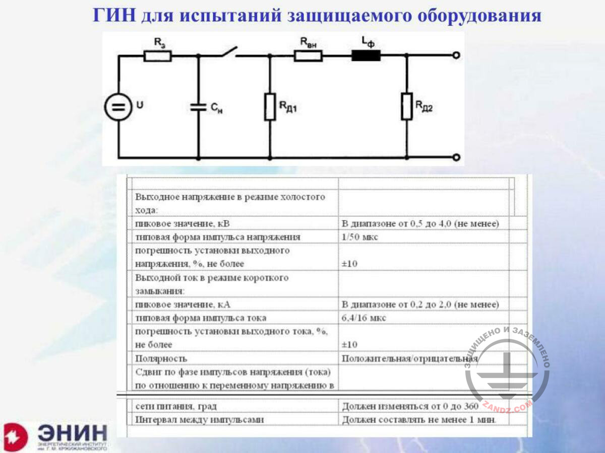
ГИН для испытаний защищаемого оборудования
Выходное напряжение в режиме холостого хода:
Пиковое значение, кВ
В диапазоне от 0,5 до 4,0 (не менее)
Типовая форма импульса напряжения
1/50 мкс
Погрешность установки выходного напряжения, %, не более
Выходной ток в режиме короткого замыкания:
Пиковое значение, кА
В диапазоне от 0,2 до 2,0 (не менее)
Типовая форма импульса тока
6,4/16 мкс
Погрешность установки выходного тока, %, не более
Полярность
Положительная/отрицательная
Сдвиг по фазе импульсов напряжения (тока) по отношению к переменному напряжению в сети питания, град
Должен изменяться от 0 до 360
Интервал между импульсами
Должен составлять не менее 1 мин.
Pulse current generators for testing the equipment to be protected
Idle output voltage
Peak value, kV
Within the range of 0.5 to 4.0 (not less than)
Typical voltage pulse shape
1/50 mcs
Error of installation of the output voltage, %, not more than
Short circuit output voltage
Peak value, kA
Within the range of 0.2 to 2.0 (not less than)
Typical current pulse shape
6.4/16 mcs
Error of installation of output current, %, not more than
Polarity
Positive/negative
Phase shift of the voltage (current) pulses relative to the alternating voltage in the power grid, degrees
Must vary from 0 to 360
Interval between the pulses
Must be within 1 min.
<< Previous page
slides from 1 to 7
Next page >>
slides from 15 to 19 + Questions and answers
Related Articles:
 Lightning Protection of Large Territories: Parks, Grounds, Plant Territories. Page 1
 Lightning Protection of Large Territories: Parks, Grounds, Plant Territories. Page 2
 Lightning Protection of Large Territories: Parks, Grounds, Plant Territories. Page 3