Webinar text. Page 3
Introducing an SDP to the circuit to be protected
Включение УЗИП в защищаемую цепь
ГРЩ
мкГн/м
А/с
кВ
На метр длины провода!
I ступень
Introducing an SDP to the circuit to be protected
DBU
mcH/m
A/s
kV
Per 1 meter of the wire!
Stage I
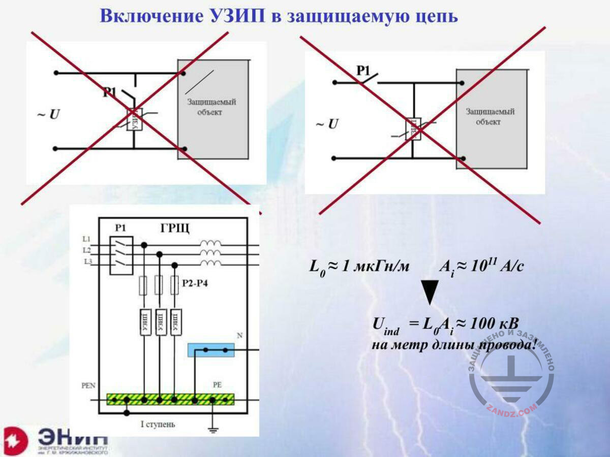
Now, the most important question is how to introduce SDPs to the electrical circuit? Many companies even hold development programmes to show engineers how to do that. Look, this is the element to be protected. I install SDP. Now, SDPs should protect this circuit. But SDP may not trigger. It may burn out. It may suppress the follow current; therefore, in any case, I must install a commutation element that should turn off my SDP when it fails, in series with the SDP. In no way it should be an automatic breaker that is installed in the low-voltage circuits. This must not be done! Why? The reason is simple. The main element of any automatic breaker is a maximum current relay. The maximum current relay is a coil. The coil has an inductance. And if you introduce such element here, this coil will be located in this circuit in series. And the lightning current will flow through the circuit. But the coil inductance multiplied by the derivative of the lightning current is an additional voltage that will occur on the coil. Imagine that you have got a small coil with the inductance of only 1 mcH, but with the lightning current steepness of 1011 A/s, which is rated in the regulatory documents, the voltage of 100 kV, 10-6 multiplied by 1011, which is equal to 105 — 100 kV, will occur on this coil. And this voltage will affect the equipment in addition to the voltage in the SDP. Therefore, no automatic breaker should be installed here. Then, the question arises. We will not install the automatic breaker here, but we will install it there. And then, if the device is damaged, the automatic breaker will trigger and turn off the failed SDP. And at the same time, it will turn off the power supply to the device to be protected. The device will be intact, but it will not work because it is not powered. And you also must not do that in any automatic circuits. What do we have to do instead? We have to do the following thing. We have to install conventional fuse elements in series with the SDP. Why do we use the fuse elements? For a very simple reason. It is because the length of the modern fuse element is one or two centimeters at most.
Installation features
ГОСТ Р МЭК 61643-12-2011
Особенности монтажа
Обеспечение селективной работы
УЗИП
Подавление паразитных колебаний
Разряд
Напряжение
Время
Недопустимо!
Предпочтительно
Возможно
Индуктивность 1 м провода ~ 1 мкГн
При
А/с
кВ/м
Хорошо, что через УЗИП проходит только малая доля тока
GOST R IEC 61643-12-2011
Installation features
Providing a selective operation
SDP
Suppressing parasitic oscillations
Discharge
Voltage
Time
Unacceptable!
Preferred
Possible
Inductance of 1 m of wire ~ 1 mcH
At
A/s
kV/m
It is good that only a small portion of the current flows through the SDP
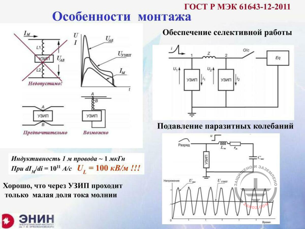
Here is the circuit and here is how I will introduce the SDP. Here, I will have two conductors. Imagine that these two conductors are half a meter each. Half a meter each is an unacceptable thing because, with the inductance of 0.5 mcH each, the induced voltage may be several dozens kilovolts that will affect the electrical circuit together with the SDP. Therefore, such connection is not acceptable. We have to install SDPs so that to completely eliminate the voltage that is added due to the inductive voltage drop in the wires. The companies that train the personnel on the SDP integration, pay much attention to this. And this question is a key. Another question is also a key. Imagine that you have got an SDP here, the equipment there, and the conductor is 20 meters long. Then, due to the parasitic inductance and parasitic capacitance of this circuit, high-frequency oscillations occur upon the SDP triggering. And such high-frequency oscillations at least double the voltage on the SDP. That is why it is strongly undesirable to provide these connecting wires from the SDP to the protected equipment with the length of at least more than 10 meters. And this aspect is also addressed during the training.
What is the fuse element required for?
Что требуется от плавкой вставки?
Импульсный ток, кА
Импульсный ток 10/350 мкс
Сгорание
Взрыв вставки
Номинальный ток вставки, А
Как быть с многокомпонентными молниями? -
- они в расчет не принимаются!
What is the fuse element required for?
Pulse current, kA
Pulse current 10/350 mcs
Burn-out
Fuse explosion
Nominal fuse current, A
How to deal with the multi-component lightnings? -
- They are not considered!
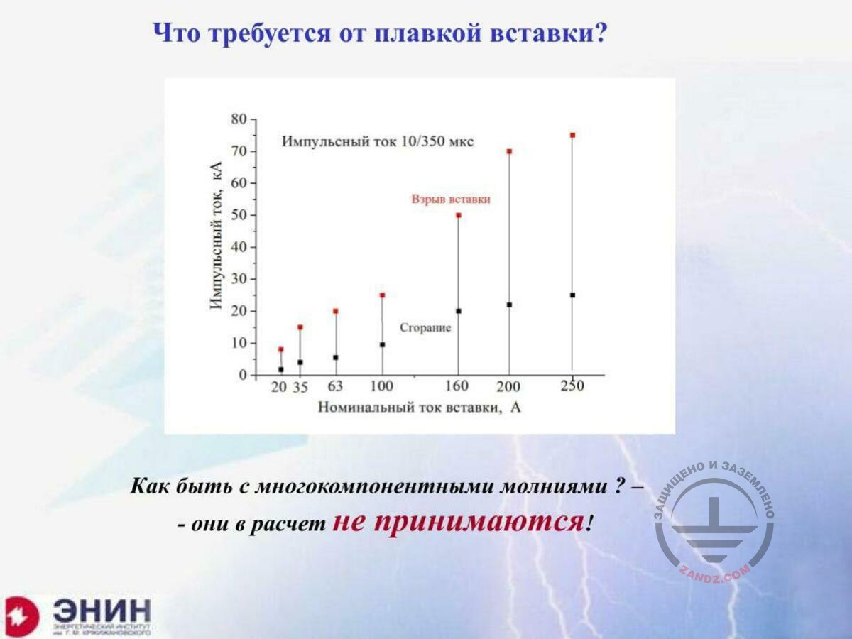
Now, the third point. What fuse elements should we choose to trigger the SDP? The fuse elements of a conventional design have got currents, at which they burn out upon the exposure to the pulse lightning current. Look, for example, the fuse element for 100 A burns out at the pulse current of about 10 kA. And the fuse element for 160 A burns out at the pulse current of 20 kA, and so on. And at the pulse current of 50 kA, the fuse element does not just burn out but it rather explodes. And explosion of the fuse element may not be allowed. Therefore, when you choose the SDP, you must choose the fuse element for this SDP, so that it would normally pass the pulse current, and upon the short circuit current, it would have burnt out without explosion and successfully shut down the electrical circuit. And this is the point that must be implemented by the designers.
Multi-stage protection
Многоступенчатая защита
УЗИП класса I
УЗИП класса II
мкГн
А/с
Ток молнии
Ток в проводах 380/220 В
ВЛ – 300 м
Ом
Время, мкс
- при равном энерговыделении
Multi-stage protection
Class I SDP
Class II SDP
mcH
A/s
Lightning current
Current in the 380/220 V wires
High-voltage power line — 300 m
Ohm
Time, mcs
- with the equal energy release
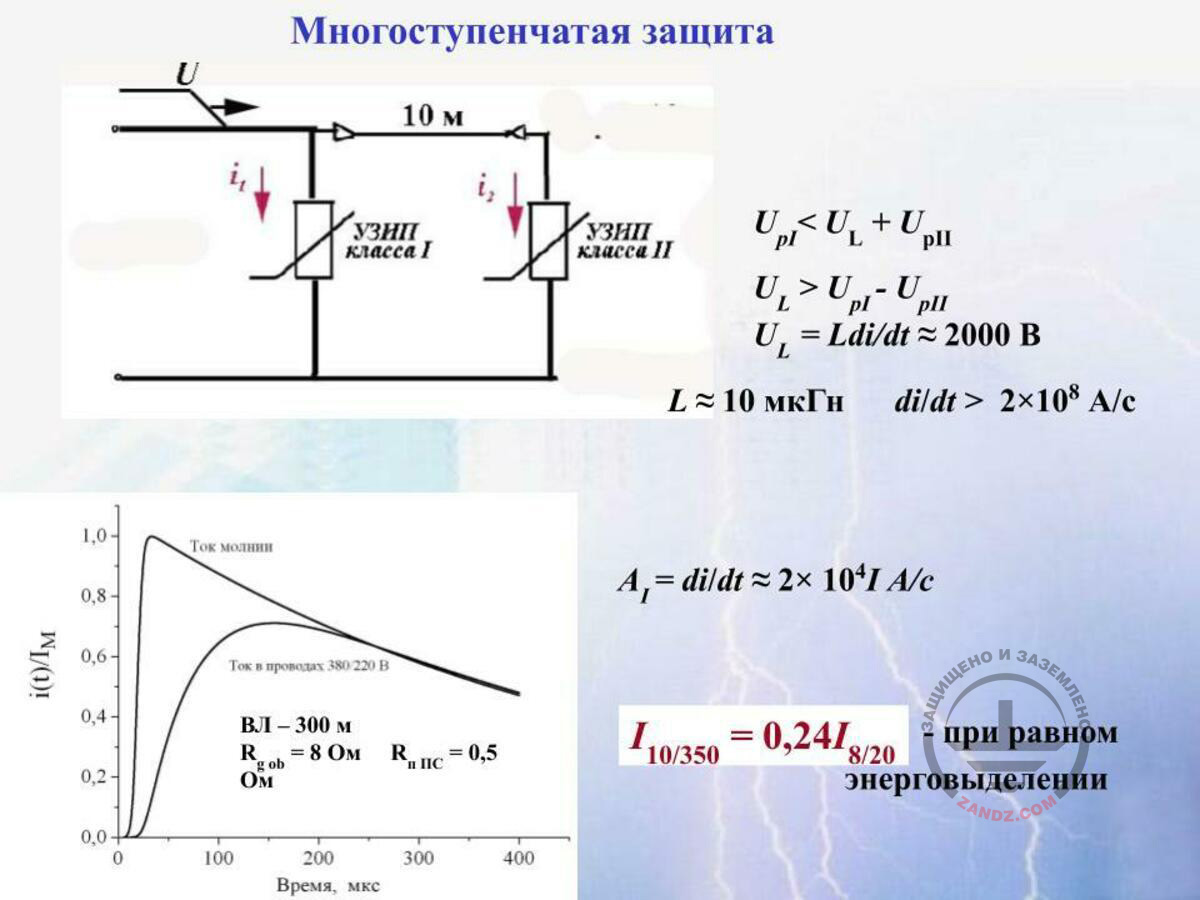
Now let's talk about one more point that I cannot avoid and that is not described at all in the regulatory documents. Imagine that you have got an electrical circuit wherein high lightning current flows. In order to pass this current, you take the SDP tested according to Class I, for example, the SDP based on the spark arrester, and install it. But this SDP based on the spark arrester has got a trigger voltage of, for example, 2.5 kV. And the equipment that is installed here has got the triggering voltage of 1 kV. And it is clear that the SDPs will not be able to protect it. Then, you need to install the SDPs tested according to Class II after the Class I SDPs. Usually, these are the SDPs based on the variable resistors with the stabilization voltage being lower than 1 kV. And sometimes we need to install the third Class III SDP that will have even a lower voltage. When you have installed everything like this, the following point is also important. It is very important that your SDPs would trigger one by one. First, the Class I SDP is triggered, then the Class II SDP is triggered, and after this the Class III SDP is triggered, and so on. If you do not provide it, and if, for example, the Class II SDP is triggered before the Class I SDP, then the entire lightning current will go through the SDP that has not been designed for it. To avoid this, the manufacturers have invented the following thing. They say that you cannot install SDPs in parallel to each other. You have to install a decoupling element, the inductance, between them. The role of this inductance may be performed either by a special solenoid or by a wire of about 10 meters long with the inductivity of about 10 mcH. Very often, the Class I SDPs are manufactured directly with the integrated throttle. All this is correct and good; however, unfortunately, it is not always like this. What is the point? What do we need to trigger the Class I SDP? We need to achieve that the voltage drop at the Class II SDPs with this inductance would be more than the triggering voltage of the spark arrester of the Class I SDP. It will only trigger in this case. If it does not happen, the Class I SDP will be useless. It just will not trigger. But the voltage at the inductance made as a wire or a solenoid is determined by two parameters: the value of this inductance and the steepness of the pulse of the current that flows. If you know the lightning current steepness as it is, you will always have a high voltage drop at this inductance, and the Class I SDP will trigger. But in the previous webinar we studied that, when the surge pulse goes along the underground utilities or goes into the air lines with resetting, the lightning current has got a very shallow front. And this front may have the duration not 10 mcs, not 1 mcs, but rather a couple of hundreds microseconds. And then the voltage drop at this inductance is insufficient to trigger the Class I SDP. And this problem is not considered by the companies that manufacture the SDPs. They forget about it. But you must not. And it turns out that the exposure of shallow voltage pulses to such multi-stage protection may be very dangerous. And we have to thoroughly analyse how the devices will operate so that to provide their correct sequence of operation. Finally, there is one more point, positive lightnings. There are not many of them. In Russia, they constitute only 10% of the total amount of lightnings. But the typical front duration of such positive pulse may be 100 mcs. And there will be no desired voltage drop at this inductance from this lightning. And, again, it is missing from all regulatory documents, but you must remember it (slide 15).
And I will tell you about one more thing. I understand that I have spent too much time, but I will tell you. Let's get back here. Here are the SDPs installed, and there are the fuse elements. The SDP is damaged here, and the fuse element has triggered and shut it down. What does the manufacturing company say? They say: so what? It has shut it down, and the signal passed to the control panel. The operating personnel have come, removed the failed SDP and the failed fuse element, and installed the new one. They have got enough time for that because the lightning strikes the typical facility once in 10 or even 30 years. They may come without hurry and replace every failed element. This is another fake that the manufacturing companies do not want to consider. During the first webinar, we discussed that the vast majority of negative lightnings, and we have got majority of them, are multi-component. Not a single current pulse will go through your circuit, and several current pulses may go through your circuits because 85% of the lightnings will lead several pulses. The first pulse has destroyed your SDP and burn out the fuse. The electrical circuit is fine, but it is left without any protection now. The next pulse will go in 60 to 80 mcs on average, and no operating personnel will have enough time to protect your equipment. The SDPs should be really designed for the multi-component lightning, but no company has been providing protection against the multi-components lightnings thus far. I can tell you that I had a trip to a large company where I offered to ensure the work on the SDP behaviour when they are exposed to the multi-component lightnings. What should we do to achieve the operability of these SDPs during the multi-component exposures? They did not understand me. Probably I will finish at this point because I have spent too much time already. If you have got any important questions, I am ready to answer them.
– Eduard Meerovich, we have got many questions, and they are large. Please clarify, how much time do we have?
– OK. I can answer for 20 minutes.
Questions and answers
– Good. Let's start then. We had several questions. I will tell you what I remember. There are the SDPs that combine several classes (I and II, II and III). What can you say about them?
– This is a very simple thing. What are the SDPs of Class I+II? These are the SDPs, which capacities correspond to the tests according to Class I, i.e. they have been tested with a powerful current pulse 10/350 mcs. And in terms of protection voltage, it corresponds to Class II or even Class III, i.e. its protection voltage is about 1–1.5 kV or 1.25 kV, and sometimes even lower. This is a good device that can be used.
– Good, thank you! One more clarification. We had a similar question from several participants: "What is the specifics of using the SDPs in the copper networks of Ethernet with PoE and RS-485? What do we have to consider in the course of making the choice?" Can you comment on this?
– I cannot comment on this because I do not understand the essence of the question. Please detail what you are talking about.
– Probably this phrase may help: "What SDP classes may be used in the low-voltage networks?"
– I was talking about the following thing. If you have got low-voltage circuits, then it is surely desirably to install the SDPs based on the variable resistor because they are cheaper and because they do not require arc-suppressing systems. But I understand that we are talking not about the variable resistor-based low-voltage circuits but rather about the low-voltage high-frequency circuits, about their protection. The protection of high-frequency circuits; the SDPs based on zinc oxide are not suitable here because they have got a high parasitic capacity. Such parasitic capacity distorts the frequency characteristics of the circuit and, as a result, the circuit does not operate normally. In order to protect high-frequency circuits, almost in all countries, the SDPs based on the high-frequency limiting diodes are usually used. These SDPs are manufactured with a special design providing coaxial connectors to eliminate reflection. And these SDPs are manufactured specifically for the installation in high-frequency circuits. And such SDP will have an indication showing which SDP is intended for what frequency range. What is the problem with it? The problem is as follows: these SDPs based on limiting diodes, I repeat, they do not have very high capacity if they are small. And they cannot pass high lightning currents. They will burn out due to the high lightning current. If you need to pass high follow current, you have to increase the SDP size. For example, they are present at the current 600 A, but such SDP has got a high area upon transition, and it has a high parasitic capacity. Due to this high parasitic capacity, it blocks the signal that is transferred along this circuit. And in this case, we have to vary in a complicated manner, and this is a very hard task although it can be solved in many cases, because you do not have so many high-frequency circuits wherein high current flows. Probably it is like this.
– Good. Thank you. One more question: "How to protect the equipment from the surge that goes through the main grounding bus (a PEN bus)? Based on the connection diagram, the SDP protects only phase conductors (TN-C system) or phased conductors and an N conductor (TN-S system).
– This is not true. At the neutral wire of the 4-wire circuit, the fourth SDP is usually installed. I have only used such diagram, but the SDP is necessarily installed at the neutral wire.
– Does the following question belong here? "I ask you to explain what a connection diagram (preferably) actually is like." I suppose it was this slide (slide 16).
– I will tell you. The point is to introduce the SDP to the electrical circuit by using as short connecting wires as possible. And now, in all instructions developed by various companies, the following thing is done. Here, the circuit goes. It goes at the angle to the SDP and goes at the angle from the SDP. And with this, the parasitic inductance almost disappears. But in certain cases, such connection cannot be made in the cabinet. And then, they offer such circuit to the manufacturing companies. You have got one conductor here, and the second conductor goes there and in an opposite direction. As a result, at this length, you have got two conductors with the same length, with the equal current that is opposed. And the inductance of the entire system is equal to zero. And only this conductor withstands the parasitic inductance. That is why, at this diagram, it is written "preferably" both in the Russian and in the European regulatory documents, because there is nothing excessive here at all, and here, this piece. This is the point. You know, these companies, in order to show how serious this issue is, make such connection in a high-voltage laboratory and install the protected elements (conductors of half a meter long) that provide a powerful lightning pulse, and only the sparks are generated in the protected element. Because the voltage drop in these two pieces of half a meter long is sufficient to burn out the protected device entirely. And then, they install such connection, and the device remains intact. When someone looks at this, he or she will say that he will not use long conductors for connection any more.
– One more clarification: "The use of fuse elements for a multi-stage SDP system will make the system expensive. What can we do? The SDP for the expensive equipment distributed throughout the facility makes the system significantly more expensive, and now we have got these fuse elements".
– Let's not cheat about the fuse elements. The price of a fuse element is a penny. But the fact that it makes the circuit more complicated is true. But today, the SDPs are often produced wherein the fuse element is integrated in the device housing. I think it is very good. However, the companies that produce such SDPs say that you do not need to perform any installations in the installation cabinet. And second, you have already paid money once and you do not need to pay more, although you have already paid for the fuse element. But you are correct. There is no other way out and we have to do that. We have to do that since there is nothing else we can do. You know that when I visited the company for the first time, where the electrical circuits are well protected, to be honest, I felt uncomfortable because I saw the cabinets with about four hundreds of such SDPs installed, with all that this fact implies. And they proudly said: "We have got such a good protection!" You know, you cannot avoid this. You have to pay for everything that is good.
– Good, thank you! Shamil clarified: "I cannot understand the difference between the "unacceptable" and "possible" diagrams. There are some activated portions of a cable. Does it mean that in case of "possible" it will also burn out? Due to the voltage drop in the cable section?"
– You know, I did not draw these diagrams. They were taken from the IEC standard. What do they want to say? They want to say that if you make it directly as it is ("Unacceptable"), then you will probably have significant interference. If you make it otherwise ("Preferred"), the interference will be minimized. If there is no way out, you can do it like this ("Possible"), but it is worse than the correct option. That is all. And this drawing has been entirely taken from the regulatory document for electromagnetic compatibility, from the IEC standard. Certainly, in the ideal case, you have to do like this ("Preferred"), but it is not possible in all cases.
– Good. Thank you. One more question: "Can we install an automatic circuit breaker instead of a fuse element? If yes, how can we choose it?" (slide 15).
– I say no categorically. I have started with that. What is an automatic fast-responding circuit breaker? The fast-responding automatic circuit breaker is a maximum current relay. What is the maximum current relay? The maximum current relay is a coil that is drawn into the core. This coil has got the inductance equal to several dozens or even several hundreds mcH. The voltage drop at this coil will be very significant. You cannot use any automatic breaker. I will get back to the drawing to stop messing with your heads. If I install the automatic circuit breaker instead of the fuse element, the voltage at this automatic circuit breaker will sum up with the voltage at the SDP and go to the protected equipment. This cannot be done categorically. You can install the automatic circuit breaker here like this, but upon its triggering, this device will remain with the shut-down circuit along which something flows to this device. If it is fine with you or if you may interrupt the operation of this device, for example, for 5 minutes, until someone comes here and turns this automatic breaker on, you can install it here. But you must not install it here because the voltage at the inductance coil sums up with the SDP voltage and will certainly damage everything you are going to protect.
– Thank you. Alexander asked to clarify the intended use of the fuse element once more: "It is required to cut off the follow current or to protect the SDP?"
– Thank you. Dear colleagues, our time is coming to an end. We have got more questions from you. If someone has not yet written his/her question, write it in the chat. We will save it and, as Eduard Meerovich said, send to him and he will try to answer if possible. Thus, we either send you the answers or, if there are many questions, we will probably have an additional meeting with Eduard Meerovich, and he will answer these questions additionally.
– But please do not think again that I know everything. I will not be able to answer the questions related to the protection specifics for some special equipment. Can you see that? I do not know this equipment and surely I will not be able to answer such questions. I ask your apologies for this. And I do not want to invent some nonsense.
– Good. Dear colleagues, thank you very much for your participation. Write your questions in the chat or in the "Questions" tab. We will save them, process, and send to Eduard Meerovich. Eduard Meerovich, thank you for your report.
– First, thank you, Anatoly, for your help. And the most important, I am thankful for that people are interested in it and they want to install the SDPs so that they would be useful. Here I repeat again the things I say all the time. You cannot treat running nose with an antibiotic drug, and you cannot install the SDPs where they are not needed. Make sure that you cannot avoid using SDP, and after that install it there. This is what I ask from you. Thank you for your attention!
– Thank you! Bye!
Thank you for attention
<< Previous page
slides from 8 to 14
Related Articles:
 Lightning Protection of Large Territories: Parks, Grounds, Plant Territories. Page 1
 Lightning Protection of Large Territories: Parks, Grounds, Plant Territories. Page 2
 Lightning Protection of Large Territories: Parks, Grounds, Plant Territories. Page 3