(held on September 5, 2018 at 11:00 Moscow time)
A series of webinars titled "Electromagnetic Compatibility with Lightning", a new book of professor E.M. Bazelyan
The third webinar will be directed to the SDPs. It is important to know when their use is feasible and how to choose the SDPs for a particular electrical circuit. A special attention will be paid to the issues, which are not addressed by the SDP manufacturers, but which are important for application.
1080p full screen watching is recommended.
Webinar text. Page 1
Approximate reading time: 55 minutes.
What if an SDP is required?
ЕСЛИ УЗИП НЕОБХОДИМ
(Что выбирать и как использовать)
Вебинар двадцать второй
Д.т.н. проф. Э.М. Базелян
АО «ЭНИН» Москва
WHAT IF AN SDP IS REQUIRED?
(What to choose and how to use)
The twenty-second webinar
Dr.Sc. (Eng.) E.M. Bazelyan
“ENIN” AO, Moscow
– Hello, Eduard Meerovich!
– Good afternoon, dear colleagues! Good afternoon, Anatoly!
– Good afternoon once again, dear colleagues! We are glad to greet you in our webinar. Today, it is the third webinar of the series titled "Electromagnetic Compatibility with Lightning". Our current webinar is titled: "When and what SDPs should we install?" The speaker is an acknowledged expert in the lightning protection and earthing, professor Eduard Meerovich Bazelyan. Let me remind you that the next webinar of Eduard Meerovich titled "Lightning Protection and Fire Safety" is preliminarily scheduled for October 3. The registration is open. I will send the link for registration in the chat. Then, I will remind you, that we also carry out a series of webinars dedicated to the BIM design. The next webinar of this series will be held on September 19. I will also send the link for registration in the chat. You can get information about our new events on the website and also in our social media groups. Our main groups will be shown in the chat. Join the social media groups or register at the website. Do not miss the relevant events. Here are some organizational aspects: our webinar will take about 70 to 80 minutes depending on your activity and the number of your questions. From my side, I ask you to be active. Leave the comments in the chat and ask questions. Note that I ask you to leave your questions in the "Questions" tab and specify, to which slide or the speaker's phrase they relate. I am going to answer a frequently asked question right now. The webinar record will be published on our website within 2 or 3 days after the webinar. If we have no technical problems, then it will be available within this period. Well, the introductory word is over and I give my turn to the speaker. Eduard Meerovich?
– Thank you very much, Anatoly! Dear colleagues, good afternoon! We have got a third seminar and I am feeling a little bit like a fish out of water. I cannot understand what is very specific about the SDPs compared to conventional lightning protection? I have been engaged in the lightning protection for over 50 years. But before that, the surge limiters had appeared and people had started to struggle with the surges. And the issue of installing arresters and limiters is the issue that had been resolved and addressed for many years. And it starts again now. What is the specifics that caused this? Why do we need a seminar on what SDPs we should install? I could not find any other answer for myself except for the following: we are talking about completely different voltage levels. Today, we are talking about the grids with the operating voltage of hundreds, dozens, or even units volts. Whereas all high-voltage equipment and all lightning protection was oriented towards kilovolt and higher voltage ranges.
Conclusion on webinar No. 20
Заключение из вебинара № 20
1. Наводки на низковольтные электрические цепи, обусловленные электромагнитным полем молнии, в ряде практических ситуаций удается снизить до безопасного уровня «естественными» средствами, применяя системы многократных молниеотводов минимально возможного превышения, дробление тока молнии по максимально возможному числу токоотводов, оптимизируя трассировку кабельных каналов и применяя экранирование электрических цепей.
2. УЗИП приходится рассматривать как основное средство защиты от резистивных наводок, которые возникают на заземлителе защищаемого объекта при распространении по нему полного тока молнии или заметной его части, занесенной по наземным и подземным коммуникациям.
Conclusion on webinar No. 20
1. Interference for low-voltage electrical circuits caused by the electromagnetic field of the lightning, in several practical situations may be lowered to the safe level using the “natural” tools, using the system of multiple lightning arresters of minimum possible elevation, splitting the lightning current among the maximum possible number of current collectors, optimizing re-routing of the cable channels, and using the electrical circuit shielding.
2. The SDPs have to be considered as a main protection means against the resistive interference that occur on the earthing device of the protected facility upon spreading the full lightning current along it or its significant portion that entered along the onground and underground utilities.
It is for this reason, in the previous seminar, we looked into the means for natural restriction of surges in details and showed that, using the rational system of lightning arresters, current collectors, earthing devices, routing of underground and onground utilities, shield may limit the surge rather significantly. And using these means, they could be restricted on a large scale, i.e. it was like an area shoot. If I distribute the lightning current correctly, the surge is reduced immediately in many circuits. It was attractive and it was the message I wanted to convey to the designers who could thereby limit the surge without the SDPs, where appropriate. And we have shown that this capability is very useful and very efficient, but it does not provide an absolute effect. The circuits always remain wherein the surge cannot be reduced lower than the particular level. First, we are talking about the resistive surges that are associated with the lightning current spread through the earthing device of a facility. In your designs, you understand it well that to make the earthing resistance of less than 1 Ohm is a rather serious problem in many cases, but to make the resistance of less than 1 Ohm in the pulse mode is a great problem. What does it mean? It means that the kiloampere current having the level of 1 kA, 2 kA, 5 kA causes the voltage drop of several kilovolts with this resistance, which is certainly fatal for the 220–380 V grids. I do not even mention the lower voltage grids and the grids intended for transfer of digital information. And in these cases, we have to use the SDPs. The SDPs must be used; they are necessary. But the question is how many SDPs we should install and how to make calculations for them?
Conclusion on webinar No. 21
Заключение из вебинара № 21
УЗИП – сильнодействующее средство, но с негативными побочными эффектами
Для решения об его установке нужны веские основания -
- тем не менее запас в расчете на 20-40% не помеха!
Conclusion on webinar No. 21
The SDP is a strong remedy having adverse effects
To decide on its installation, we need good grounds -
- nevertheless, 20–40% reserves during calculation are good!
Here, I tried to prove that the SDP is a very strong tool, but it has got rather serious negative effects that have to be taken into account. And it is understood what these consequences are related to. You introduce a device into the protected electrical circuit, inside of it. And it means that, due to its presence alone, the tool may change the electrical mode of it, may change the frequency characteristic, and may change it so that the installation of your SDP will be unacceptable and will distort the circuit mode operation such that the SDP will not be needed. In its presence, the circuit will not operate. And one more point. One more point is that these SDPs are numerous in the control circuit of a facility, and the SDPs are the elements without an absolute reliability. And it turns out that the SDPs presence begins decreasing the entire control system operation reliability. If you have got many SDPs, and sometimes their numbers reach hundreds or even thousands, the system's reliability in general is determined by the reliability of the SDP operation. And this point is unacceptable. And finally, the point is that the SDPs are calculated using a rather complex solution of current distribution in electromagnetic fields. The initial data for all of these is the lightning current statistics. Such statistics is not so much reliable to trust it without any doubts.
SDP operating principle
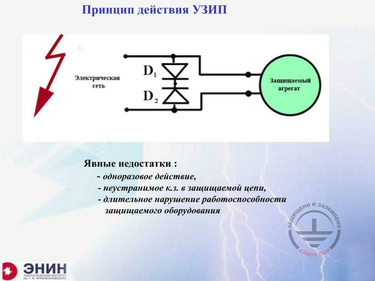
Принцип действия УЗИП
Электрическая сеть
Защищаемый агрегат
Явные недостатки:
- одноразовое действие,
- неустранимое к.з. в защищаемой цепи,
- длительное нарушение работоспособности защищаемого оборудования
SDP operating principle
Electrical grid
A unit to be protected
Obvious drawbacks:
- single use,
- unrecoverable short circuit in the protected circuit,
- long-term impairment of the protected equipment operation
What is an SDP in terms of the electrical circuit theory? It is a device that will be damaged earlier than the protected facility. Around 30 years ago, we conducted a rather complex experiment that included the sensor that was hard to manufacture. This sensor was damaged when the electrical insulation breakthrough occurred in a multi-meter charge gap we studied. We felt sorry about the sensors as it was hard to manufacture them. And we made such simple protection as shown in this picture. We added two pulse diodes opposite to each other in a sensor circuit. At that time, we had no SDPs. Such diodes had a low cross capacitance. They did not interfere with the useful signal passage. And when the circuit was damaged, high current burnt out these sensors and created a short circuit. It was essentially an SDP that nobody would have taken a risk to use now. Why? First, it was a single-use device. It just burnt out when it restricted the surge. Second, this SDP, after the voltage pulse disappeared, did not allow to turn on the device because it created a mechanical short circuit. Today, it is absolutely unacceptable because the protected element must continue operating when the surge dissapears. And such device did not allow this. And third, in most electrical circuits, a follow current flows across the short circuit. Such follow current had to be eliminated. However, our device did not allow any follow current and did not eliminate it. Therefore, the SDP development includes only the following aspects. First aspect: if I introduced it into the circuit, my circuit should not detect its presence. It means that the SDP should not pass the current therethrough in a normal mode and should not change the circuit frequency characteristic with its parasitic elements (first of all, the parasitic capacitance). Second, when the SDP is triggered, its voltage should be lower than the voltage that could have been withstood by the protected equipment. It is the second aspect. The third aspect is that, after the surge disappearance, the SDPs must transit to the initial state, eliminating the follow current, if any. And thus do not interrupt the operation of the device to be protected. And all of these requirements should be accompanied by many aspects that are not less important. And many aspects are: I must trigger so quickly that the surge would not have enough time to damage the protected element. And if this is a low-voltage element, the low-voltage insulation, then during the breakthrough of this low-voltage insulation, the protection must be provided, in the best case, during fractions of a microsecond, or sometimes even several nanoseconds or even a fraction of a nanosecond. It means that my protective device, the SDP, must operate quickly. And finally, the last aspect. I must meet the requirements to temperature, pressure, and fire and explosion safety in the SDP location. It is for this reason, due to a large number of these requirements, the SDP catalogues that are provided by most advanced technical companies that manufacture them contain hundreds of pages of the A4 format. This is due to a large variety of the SDPs. The SDP requirements are too specific.
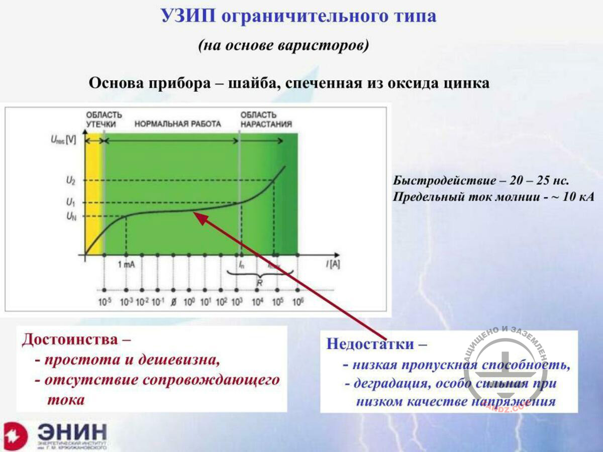
Limiting-type SDP
УЗИП ограничительного типа
Основа прибора – шайба, спеченная из оксида цинка
ОБЛАСТЬ УТЕЧКИ
НОРМАЛЬНАЯ РАБОТА
ОБЛАСТЬ НАРАСТАНИЯ
Быстродействие – 20-25 нс.
Предельный ток молнии - ~ 10 кА
Достоинства -
-простота и дешевизна,
- отсутствие сопровождающего тока
Недостатки -
- низкая пропускная способность,
- деградация, особо сильная при низком качестве напряжения
Limiting-type SDP
Device base: a washer sintered from the zinc oxide
LEAKAGE AREA
NORMAL OPERATION
BUILDUP REGION
Response time — 20–25 ns.
Maximum lightning current — ~ 10 kA
Advantages -
- simple and cheap,
- no follow current
Disadvantages -
- low capacity,
- degradation that is especially strong in low-voltage quality
And now, taking into account these requirements, let's see what we have got. Generally, most often, the lightning protection and electromagnetic compatibility experts have to choose between two SDP types. Limiting-type SDP is based on a variable resistor and switching-type SDP is based on a good old spark gap that appeared in the electrical engineering at least one hundred years ago. Variable resistor-based SDP. Here is a colorful picture you can see that represents a volt-ampere characteristic of such SDP. At the rated voltage, the SDP is almost entirely an insulator. These are the currents at the level of several microamperes. Such currents provide almost no energy emission, the washer is most often made of zinc oxide; it is a very cheap washer. It is not heated, and the SDP does not affect the electrical circuit I install it to. When the voltage increases at the SDP and when it reaches the level that exceeds the rated voltage in the electrical circuit, the currents flowing through the SDP reach several units or even dozens milliamperes. And in this case, the frequency characteristic of the SDP, in this section of the SDP, its volt-ampere characteristic is almost horizontal. It means that the SDP voltage does not almost grow with the current change. It is a working part of the SDP characteristic that stabilizes the voltage in the electrical circuit in spite of the singificant input resistance and high current that is created, e.g., by the storm surge. It is a useful part of the characteristics, and it is its working part. Such working characteristic in small SDPs reaches the current of about a unit or, in the best case, dozens kiloamperes. And then it starts growing significantly, and the voltage stabilization stops. And high energy is released in the SDP that may destroy it. And now we have got the following thing. We have got a surge limiter with at least two advantages. The first thing is its simple structure, while the second thing is the absence of the follow current. Because as soon as the surge disappears, the normal surviving SDP goes here again. And transition from one state to another in such a variable resistor based on the zinc oxide occurs rapidly. This is not more than 20 to 25 nanoseconds. And it means that such washer made of zinc oxide may be used for limiting rapidly growing surges. This is because 20 to 25 nanoseconds is a very good working time. What is its major disadvantage? And the major disadvantage is, again, in this characteristic. Such voltage at the SDP is actually at the level of hundreds kilovolts. And if significant kiloampere currents flow with such voltage, a very high energy is released, power, UI. The SDP is quickly overheated and destroyed. Therefore, it is almost impossible to create an SDP based on variable resistor with the current of more than 10 kA, maximum 20 kA. It is impossible because they are not created for such currents. And the second unattractive thing is associated with that the SDP is prone to degradation. What does it mean? It means that if you have a low voltage quality, e.g., if you have installed the SDP in the 220–380 V country grid, wherein due to the phase distortion you have 250 V or even 270 V per phase instead of 220 V. I live outside the city and I know about it. What does it result in? It results in a slight opening of the SDP. The current starts flowing through it, the currents at the level of milliamperes or even dozens milliamperes. There is no current collector. The washer made of zinc oxide heats rapidly. It changes its characteristics or even destroys it. This fact, the instability of the SDP characteristics, makes them slightly suitable for using in the critical electrical circuits where they have to pass rather significant lightning currents.
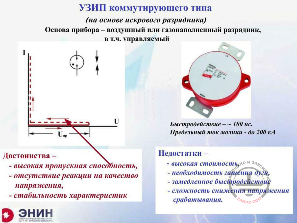
Switching-type SDP
УЗИП коммутирующего типа
(на основе искрового разрядника)
Основа прибора – воздушный или газонаполненный разрядник, в т.ч. управляемый
Быстродействие ~ 100 нс.
Предельный ток молнии – до 200 кА
Достоинства -
-высокая пропускная способность,
- отсутствие реакции на качество напряжения,
- стабильность характеристик
Недостатки -
-высокая стоимость,
- необходимость гашения дуги,
- замедленное быстродействие,
-сложность снижения напряжения срабатывания.
Switching-type SDP
(based on the spark arrester)
Device base: air or gas filled arrester, including controlled
Response time ~ 100 ns.
Maximum lightning current — up to 200 kA
Advantages -
- high capacity,
- no reaction to the voltage quality,
- stable characteristics.
Disadvantages -
- high value,
- need to suppress the arc,
- slower response,
- difficult to reduce the triggering voltage.
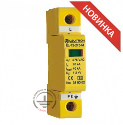
And now let's talk about the SDP based on an arrester, the switching-type SDP. I want to show you its volt-ampere characteristics from the very beginning. The voltage grows, no current flows through the SPD because its spark arrester is not broken through. When the voltage reaches the arrester breakthrough level, the arrester is broken through. The spark channel turns into an arc rapidly and the current increase through this device is not associated with the voltage increase. The voltage at the broken spark gap of the SDP is 10 to 12 V, or at most 15 V. It means that the energy that is released as a current multiplied by the voltage, is low. And the SDPs may be intended for very high currents. I contacted my acquaintances so that they would show me the SDPs with the largest possible currents, and they sent me this photo. Such SDP for 200 kA is capable of passing the currents with the pulse of 10 for 350, which is a typical pulse simulating the current of the first lightning component. But SDP for 100 kA, for 150 kA, are ordinary SDPs that are manufactured by many companies. These SDPs may be inserted in the housings that are typical for the low-voltage equipment, e.g., for the automation equipment or arresters. I have already described the advantage of such SDP. It may pass very high currents. Now, let's talk about its disadvantages. There are two rather serious disadvantages. If the arrester has been broken through, such arrester will pass the follow current after the storm surge has disappeared. The voltage of 220 V electrical grid is enough for this. And the follow current will flow through such arrester. Its value is determined by the power of the source that supplies this circuit. And such follow current may be of several or even dozens kiloamperes. This current will not be eliminated by itself, it has to be eliminated. And to eliminate it, we have to provide the SDP with an arc-suppressing camera that may operate according to different principles, but it must be present. And the SDP's ability to suppress the follow current is its important characteristic. Currently, the SDPs exist that may suppress the industrial frequency follow current of about up to 50 kA. Such SDPs really exist. But you understand that if I add an arc-suppressing camera into the SDP, it becomes more complex and expensive. The second disadvantage is also a rather serious one. The spark gap. If it is an SDP made in the air gap, the value of this gap cannot be less than one millimeter. And it means that the breakthrough voltage for such gap will be 2.5 to 3 kV. The SDP will not trigger at the lower voltage. This is very bad because the fractions of its surge triggering of up to 2.5 to 3 kV go to the protected equipment. We have to try to reduce the trigger voltage of the SDP's spark gap, if this is possible. It can be achieved in two ways. The first way is to install the SDP not in the air but in the low-strength gas, e.g., in argon and neon, or some other noble gases mix. It allows reducing the trigger voltage of the SDP, but, in this case, it cannot pass high currents because the glass flask will just break down at high current. The second point is to create a controlled SDP in the air. A three-electrode SDP is made with a special burning due to which the voltage can be reduced from about 2.5–3 kV to 1.5 kV or even to 1.2–1.25 kV. You may say: "This is a nonsense! The voltage is reduced two times." It is not a nonsense. First, it is rather difficult because the SDP becomes even more complex and, therefore, expensive. And second, the reduction from 2.5 to 1.5 kV or to 1.25 kV allows protecting the 220 V electrical circuits with the electrical strength of around 2.5 kV. This is a very important issue, and I will highlight it once again: the point is that I have to use a very expensive device. And due to the fact that it is very expensive, it is certainly more difficult to use it.
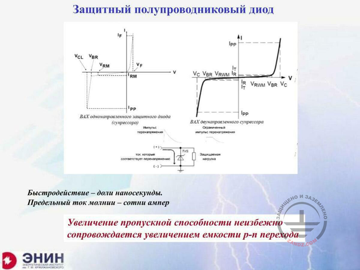
Protective semiconductor diode
Защитный полупроводниковый диод
ВАХ однонаправленного защитного диода (супрессора)
ВАХ двунаправленного супрессора
Ограниченный импульс перенапряжения
Импульс перенапряжения
Ток, который соответствует перенапряжению
Защищаемая нагрузка
Быстродействие – доли наносекунды.
Предельный ток молнии - сотни ампер
Увеличение пропускной способности неизбежно сопровождается увеличением емкости p-n перехода
Protective semiconductor diode
Current-voltage curve of an unidirectional protective diode (suppressor)
Current-voltage curve of a two-directional suppressor
Limited surge pulse
Surge pulse
The current corresponding to the surge
Protected load
Response time — fractions of a nanosecond
Threshold lightning current — hundreds amperes
Increasing the capacity is always accompanied by the increase in the p-n transition capacity
There is one more point. The spark arresters are not broken through very quickly. The trigger time for the spark arrester is about 100 nanoseconds. Therefore, the SDPs based on the spark arrester protect circuits where no rapid triggering is required. And if a rapid triggering is required, we have to use the SDPs of the third type. These are SDPs based on a protective semiconductor diode. These SDPs operate as follows. The p-n transition is broken through very rapidly, for several fractions, tenth or even hundredth fractions of a nanosecond. And this semiconductor transition also returns quickly to its initial state. But the capacity of these devices in terms of the lightning current is not high. And the main point is that to pass the currents of at least hundreds amperes (and high currents are not considered), you have to make the p-n transition with a fairly large area.
Next page >>
slides from 8 to 14
Related Articles:
 Methodics of calculation of SPD load currents
 Webinar «Frequently asked questions about SPDs», page 1
 SPD - reliable protection for complex electronics
 Lightning Protection of Large Territories: Parks, Grounds, Plant Territories. Page 1
 Lightning Protection of Large Territories: Parks, Grounds, Plant Territories. Page 2
 Lightning Protection of Large Territories: Parks, Grounds, Plant Territories. Page 3