The thirteenth webinar of a series "Grounding and lightning protection: issues and problems arising during design"
(was held on February 10, 2016 at 11:00)
Full-screen mode with the quality of "720p" is recommended.
This year we are holding another webinar on the use of SPDs to limit surges in low-voltage electrical circuits. The reason for this is the numerous questions from the designers of internal lightning protection. Their cause is trivial enough. Russian lightning protection regulations cover the practical application of SPDs in very general terms, and only in SO 153-34.21.122-2003 instructions. There are no specific requirements, so the designers are left alone with the recommendations of SPD manufacturers. The situation is vague. Manufacturers are primarily interested in the mass sales of products that are the easiest to manufacture and expensive. For this purpose, they issue brochures with the basic assessment of storm surge levels and lightning currents coming through the SPDs, which clearly tend to turn designers' attention to the "right" security elements.
Today, due to the serious financial complications in the country, such a situation can hardly be considered acceptable. An evidence-based guidance for the selection of SPDs based on the reliable calculations of thunderstorm surges and current loads is desperately needed. The upcoming seminar will lay a basis for solving this problem.
It worth reminding once again that the placement of SPDs in an electrical circuit is a very potent tool. Its use is justified only in the case if all possibilities to limit dangerous lightning effects through the installation of external lightning protection devices have been exhausted. Much-hyped typical examples with hundreds of SPDs installed in the circuits of the protected facility cannot be considered a viable solution, as any SPD is quite a complex appliance with a very specific reliability. Its very presence in the circuit may adversely affect the reliability of the whole facility and its technical specifications.
Designers should always pursue a task of minimizing the number of SPDs. This is hardly possible without a reliable assessment of hazardous lightning effects on the protected equipment and their comparison with the permissible parameters specified by the manufacturer.
To demonstrate the above, we relied on specific questions asked by the audience. Most of these questions were answered either in the form specific recommendations or as guidelines to the quantitative method of solving the problem.
Webinar text. Page 1
Estimated reading time: 64 minutes
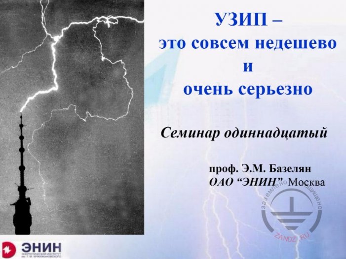
SPD is very serious and requires costs
УЗИП – это совсем недешево и очень серьезно
Семинар одиннадцатый
Проф. Э.М. Базелян
ОАО «ЭНИН» Москва
Заземлено и защищено
ЭНИН
SPD is very serious and requires costs
The eleventh workshop
Professor E.M. Bazelyan
JSC “ENIN” Moscow
Grounded and Protected
ENIN
— Today we hold the eleventh webinar with professor discussing surge protection devices to be an acute issue. These are surge protection devices or SPDs. Previously, we collected questions of designers to understand, which are the problems in design, selection and installation of surge protection devices. These questions were sent to professor, who will bring the light on them today. Now, my welcome speech ends. I give the floor to Mr. Bazelyan. Greetings! May we start?
— Good afternoon, Alexey! Good afternoon, dear audience, colleagues. Maybe I should say I'm very happy to be there. Unfortunately, the joy is only one side. This is the second webinar on this subject and I understand the situation of SPDs remains complicated for designers. I know why. SPDs are designed by companies engaged in utilities supply to buildings and facilities. These are the people knowing power industry well. They are able to design required networks properly, but installation of SPDs relates to a kind of the other specialization. Any power supply company has a high voltage laboratory engaged in suppression of surges. These people trained absolutely in other way, because overvoltage always is pulse transient process to be calculated by using other methods. And the experience we have is quite the other experience. I tried to study the following aspect during preparation for this workshop. Now I take our national regulatory documents and see if the designer can do something he does not understand based on relevant codes and standards.
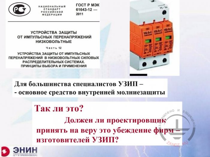
International Electrotechnical Commission Standard
Национальный стандарт Российской Федерации
ГОСТ Р МЭК
Устройства защиты от импульсных перенапряжений
Низковольтные
Часть 12
Устройства защиты от импульсных перенапряжений в низковольтных силовых распределительных системах. Принципы выбора и применения.
Для большинства специалистов УЗИП – основное средство внутренней молниезащиты
Так ли это?
Должен ли проектировщик принять на веру это убеждение фирм изготовителей УЗИП?
Заземлено и защищено
ЭНИН
National Standard of the Russian Federation
GOST R IEC
Surge Protection Devices
Low-voltage
Part 12
Surge protection devices in low-voltage power distribution systems. Selection and application principles.
In opinion of the most of specialists, SPD is main tool for internal lightning protection
Is it true?
Should designer rely upon this statement of SPD manufacturers?
Grounded and Protected
ENIN
- Principal document is the standard of the International Electrotechnical Commission, IEC Standard which was translated into Russian, it is named as surge protection device in high-voltage networks. I looked through this standard and found, that any designer referring to it will get no useful information at all. What should the designer do? He is forced to do the following. Search in the Internet trying to select relevant articles and recommendations. I tried to do the same. Look what I found. I found many articles with recommendations. Authors of them are SPD manufacturers but not designers of SPD installation. These articles have one only goal, that is to say sale of SPDs more and more. Because of that goal of recommendations, they confuse designers again. What to say? Once looking at all these articles, SPDs seem to be the only thing protecting against overvoltage. I have a question, "is It really so?". Yes it is, if you trust recommendations of companies. Companies present certain recommendations, even specific standard designs. For example, I counted about 1,500 SPDs in one of such standard design for an industrial enterprise. First, SPD price is not much affordable today, look at one shown in the poster here, the price of SPD is approaching 500$. 500$ seem to be high, such costs shall be reasonable. Especially, when your number of SPDs is many dozens or hundreds. But, stop, who needs it? Can this situation be normally accepted? One only thing for overvoltage protection is a surge protection device. I have strong doubts in this regard. The same was at our first webinar devoted to SPD, wasn't it?
SPD is effective solution
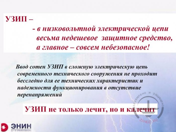
УЗИП -
- в низковольтной электрической цепи весьма недешевое защитное средств, а главное – совсем небезопасное!
Ввод сотен УЗИП в сложную электрическую цепь современного …
УЗИП не только лечит, но и калечит
Заземлено и защищено
ЭНИН
SPD -
- in low-voltage electrical circuit it is rather expensive protective device, moreover, it is not safe at all!
Installation of hundreds of SPDs into complex electric circuit of modern engineering facility affects characteristics hereof and reliability of functioning without overvoltage
SPD advantages are counterbalanced by disadvantages
Grounded and Protected
ENIN
- We discussed that issue and agreed that SPD is a state-of-the-art device for surge protection, and the same as for all effective solutions, SPD is not safe for following reasons. Having dozens or hundreds of electronic devices installed in any electrical circuit results in change of reliability hereof. This will be changed at least because of reliability of SPDs themselves, which is certainly has the coefficient other than one. Installation of dozens and hundreds of SPDs in high-voltage circuit will result in change of reliability hereof, moreover, in change of technical characteristics hereof.
Physical mechanism of lightning overvoltages. Part 1
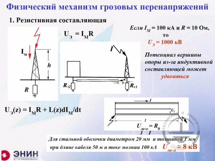
Физический механизм грозовых перенапряжений
1. Резистивная составляющая
Если
кА
и
Ом
то
кВ
Потенциал вершины опоры из-за индуктивной составляющей может удвоиться
Для стальной оболочки диаметром 20 мм и толщиной 1 мм при длине кабеля 50 м и токе молнии 100 кА
Заземлено и защищено
ЭНИН
Physical mechanism of lightning overvoltages
1. Resistive component
If
kA
and
Ohm
then
kV
Support top potential due to inductive component can be doubled
For steel clad with diameter of 20 mm and thickness of 1 mm with the cable length of 50 m and lightning current of 100 kA
Grounded and Protected
ENIN
- First of all, I shall begin with explanation of the nature of these overvoltages occurring in electrical circuits. These may be of two kinds. First overvoltage from a direct lightning strike. The lightning strikes, for example, power transmission line, current runs by cables hereof, by grounding of supports and induced by it the voltage arises which affects electrical network through cables. Peculiarity of these overvoltages is that rather high current runs through protective devices intended for surge suppression. This current may form part of the lightning current, being the most part hereof. One shall be capable to determine which this lightning current part will be in this case. It is very critical and serious issue to be resolved.
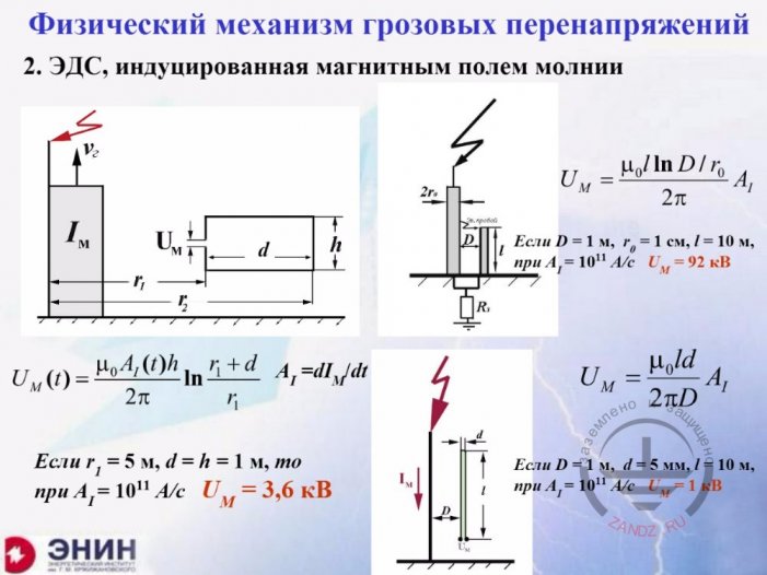
Physical mechanism of lightning overvoltages. Part 2
Физический механизм грозовых перенапряжений
2. ЭДС, индуцированная магнитным полем молнии
Если
м
см
при
кВ
мм
Заземлено и защищено
ЭНИН
Physical mechanism of lightning overvoltages.
2. EMF induced by lightning magnet field
If
m
cm
At
kV
mm
Grounded and Protected
ENIN
- The second thing is about the following. The second thing concerns induced overvoltages. You have the lightning current running somewhere. It can run in the lightning channel, in the lightning rod, in down conductors, and everywhere there is magnet field around this current. This magnet field causes EMF of magnetic induction in all circuits connected to that field. This is other kind of overvoltages. It is specific by, as a rule, decreased level of overvoltage, whereas it of course represents a high risk for low-voltage electrical circuits. And the current running in this case through protective device is considerably lower.
Surge suppression means
Средства ограничения перенапряжений
- оптимальная трассировка и ориентировка электрических цепей объекта,
- безопасный транспорт тока молнии в землю по токоотводам,
- экранирование электрических цепей,
- установка УЗИП
Заземлено и защищено
ЭНИН
Surge protection means
- optimum layout and orientation of facility electric circuits,
- safe transport of lightning current into the ground by down conductors,
- shielding of electric circuits,
- installation of SPDs
Grounded and Protected
ENIN
- Before understanding which SPDs shall be installed and with what number, one shall determine the following: maybe we can suppress overvoltage by other means, not SPDs? What these means can be? First of all, it is harnessing of those electrical circuits to be protected. Overvoltages will vary depending on layout of electrical circuits. This more concerns induced overvoltages. The second thing, try to transport lightning currents into the ground in a safe way. "Safe" here means the following: if you break down the lightning current by many ways with high number of down conductors, more likely, that overvoltage will be decreased inside the building space to which these down conductors are connected.
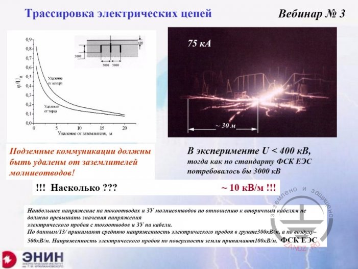
Harnessing of electrical circuits
Трассировка электрических цепей
Вебинар №3
75 кА
Удаление от торца
Удаление от заземлителя, м
Подземные коммуникации должны быт удалены от заземлителей молниеотводов!
Насколько???
В эксперименте U < 400 кВ, тогда как по стандарту ФСК ЕЭС потребовалось бы 3000 кВ
∼10 кВ/м!!!
Наибольшее напряжение на токоотводах и ЗУ молниеотводов по отношению к вторичным кабелям не должно превышать значения напряжения электрического пробоя с токоотводов и ЗУ на кабели.
По данным/13/ принимают среднюю напряженность электрического пробоя в грунте 300 кВ/м, а по воздуху – 500 кВ/м. Напряженность электрического пробоя по поверхности земли принимают 100 кВ/м.
ФСК ЕЭС
Заземлено и защищено
ЭНИН
Layout of electrical circuits
Webinar No.3
7 kA
Distance from the end
Distance from the grounding rod, m
Underground communications shall be at the distance from lightning rod grounding electrodes!
What is the distance???
According to experiment U < 400 kV, whereas according to FGC UES 3,000 kV would be required
∼10 kV/m!!!
The highest voltage on down conductors and lightning rod grounding electrodes relative to secondary cables shall not exceed the value of voltage of electrical breakdown from down conductors and grounding electrodes to cables.
According to/13/ mean strength of the electrical breakdown in soil shall be taken 300 kV/m, and in the air, 500 kV/m. Electrical breakdown strength by the ground surface shall be taken 100 kV/m.
FGC UES
Grounded and Protected
ENIN
- You know that this issue was discussed at the workshop No.3, with many details. However, one thing I should say. At least one thing I should say. First of all, harnessing. What is meant by that? Two different factors. The first factor, you have a grounding electrode with the lightning current going by it. For example, this can be the grounding electrode of "well-arranged" lightning rod, through which the lightning current runs into the ground, but there is a route of underground cable laid near. Let it be data cable from microelectronic device or reliable power supply of that microelectronic device. You install the rod, by observing distances between the grounding electrode and that cable according to the document RD-34 or to departmental regulatory documents, for example, SO standard. In any way, this distance will be at least several metres. And what can we see from experiments carried out properly, of course? It is the following thing. Instead of 300 kV per metre which is considered to be breakdown distance in the ground, in fact, the ground is broken down by high lightning currents with the voltage of about 10 kV per metre. It is not a missay. The difference between calculated value and real one is about 30 times. This is real experiment. Of course, in order to protect these cables, one shall take into account this fact.
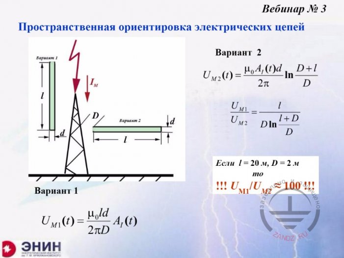
Spatial orientation of electric circuits
Вебинар №3
Пространственная ориентировка электрических цепей
Вариант 1
Вариант 2
Если
м
то
Заземлено и защищено
ЭНИН
Webinar No.3
Spatial orientation of electric circuits
Variant 1
Variant 2
If
m
then
Grounded and Protected
ENIN
- There is the second option. The situation is as follows. The lightning current runs, for example, by down conductor or the lightning rod, it doesn't matter. You have an electrical circuit. You may arrange this electrical circuit along the lightning current path as shown in figure on the left, or you may arrange it crosswise, as shown in figure on the right. Overvoltage will also be different in this case. Whereas, when the channel is generated crosswise, overvoltage level will differ from one with parallel arrangement, again, by dozens of times, even hundred-time difference. And if you arrange protected electrical circuit relative to the current conductor in a proper way, you may decrease overvoltages to such a serious extent that no SPDs will be required at all.
Safe transport of lightning current into the ground
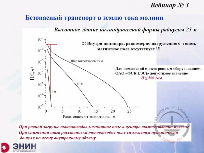
Вебинар №3
Безопасный транспорт в землю тока молнии
Высотное здание цилиндрической формы радиусом 25 м
Внутри цилиндра, равномерно нагруженного током, магнитное поле отсутствует!!!
Шаг токоотводов 25 м
м
Для помещений с электронным оборудованием ОАО «ФСК ЕЭС» допустимое значение
А/м
Расстояние от токоотвода, м
При равной загрузке токоотводов магнитное поле в центре тождественно нулевое
При снижении шага расстановки токоотводов поле снижается практически до нуля по всему внутреннему объему
Заземлено и защищено
ЭНИН
Webinar No.3
Safe transport of lightning current into the ground
High-rise building of cylindrical shape with the radius of 25 m
There is no magnet field inside cylinder loaded with current uniformly!!!
Down conductors spacing 25 m
m
For rooms with electronic equipment, permissible value as per JSC FGC UEC
A/m
Distance from down conductor, m
With uniform loading of down conductors, magnet field in the center is identically equal to zero
With spacing of arrangement of down conductors the field is decreased virtually to zero along the whole internal volume
Grounded and Protected
ENIN
- Now, let's take a look to one more thing, which also was discussed at the last webinar, what is safe lightning current transport into the ground. Safe lightning current transport into the ground always is breaking down of current by high number of down conductors. This graph shows change of magnet field strength when, for example, fifty down conductors are taken with the spacing of 1-2 metre instead of two down conductors. Where these down conductors will be taken from? The reason is simple. For example, the building includes metal columns which may function as down conductors.
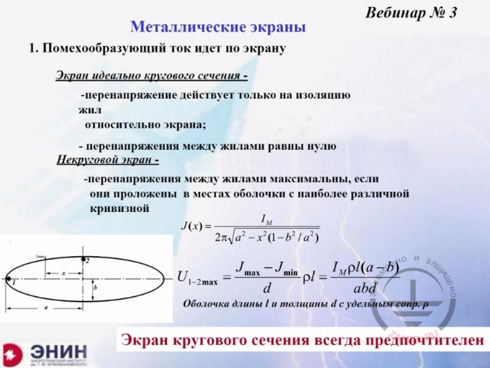
Metal shields. Part 1
Вебинар №3
Металлические экраны
1. Помехообразующий ток идет по экрану
Экран идеально кругового сечения -
- перенапряжение действует только на изоляцию жил относительно экрана;
- перенапряжения между жилами равны нулю
Некруговой экран -
- перенапряжения между жилами максимальны, если они проложены в местах оболочки с наиболее различной кривизной
Оболочка длины l и толщины d с удельным сопр. P
Экран кругового сечения всегда предпочтителен
Заземлено и защищено
ЭНИН
Webinar No.3
Metal shields
1. Interference-generating current is running by the shield
The shield has ideally round cross-section -
- overvoltage affects only the insulation of wires relative to the shield;
- overvoltages between wires are equal to zero
Non-circular shield -
- overvoltage between wires is maximum, if these are laid at location of shields with the maximum difference of curvature
Shield of the length l and thickness d with specific resistance p
Round cross-section shield is always preferred
Grounded and Protected
ENIN
- Finally, one more thing. Metal shield also mentioned at last webinar. Metal shields: in any situation, the best metal shield is round metal pipe, round shape is important. Rectangular conduit or any ellipsoidal structure drawn here. Unfortunately, it has low overvoltage suppression capacity. If you really want to make shielded structure, then round cross-section will give an optimum effect. Optimum, even the current is running by that structure. Imagine the situation, for example, when current is running by shield. For example, there is a lamp in an airport or railway switching yard. The lamp is hanging on the pole. The pole is used as the lightning rod, the lamp is energized by means of shielded cable. If shielded cable will be connected to round metal pipe, then, regardless almost the whole lightning current is running by it, overvoltages will be reduced sharply. The situation of rectangular cross-section conduit. Reduction will not be much effective.
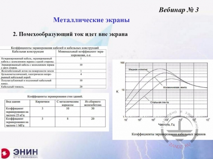
Metal shields. Part 2
Вебинар №3
Металлические экраны
2. Помехообразующий ток идет вне экрана
Коэффициенты экранирования кабелей и кабельных конструкций
Кабельная конструкция
Минимальный коэффициент экранирования, о.е.
Неэкранированный кабель, экранированный кабель с заземлением экрана с одной стороны
Экранированный кабель с заземлением экрана с двух сторон
Железобетонный лоток по поверхности земли
Цельнометаллический, электрически непрерывный кабельный короб
Полузаглубленный и подземный кабельный канал,
Кабельный тоннель
Коэффициенты экранирования стен зданий
Вид здания
Кирпичное
С металлическим каркасом
Из сборного железобетона
Коэффициент экранирования на частоте 25 кГц
Коэффициент экранирования на частоте 1 МГц
Медная оплетка
Алюминиевая лента
Стальная лента
Частота, Гц
Коэффициенты экранирования кабельных экранов
Заземлено и защищено
ЭНИН
Webinar No.3
Metal shields
2. Interference-generating current runs beyond the shield
Shielding coefficients of cables and cable structures
Cable structure
Minimum shielding coefficient, p.u.
Not shielded cable, shielded cable with shield grounding on the one end
Shielded cable with shield grounding on both ends
Reinforced concrete tray by the ground surface
Full-metal electrically continuous cable conduit
Semi-buried and underground cable channel,
Cable tunnel
Building walls shielding coefficients
Building type
Brick
With metal carcass
Reinforced concrete
Shielding coefficient at the frequency of 25 kHz
Shielding coefficient at the frequency of 1 MHz
Copper braiding
Aluminum strip
Steel strip
Frequency, Hz
Shielding coefficients of cable shield
Grounded and Protected
ENIN
- Finally, shielding against external fields is also rather effective, if you use round cross-section metal shields, even made of steel. Copper and aluminum ones far more effective. If all possibilities are exhausted and you see that overvoltage is still dangerous for the electric circuit to be protected or for the equipment in it, this is the only case when SPDs using is reasonable and these need to be designed.
Next Page >>
Slides from 12 to 22
Related Articles:
 Lightning Protection of Large Territories: Parks, Grounds, Plant Territories. Page 1
 Lightning Protection of Large Territories: Parks, Grounds, Plant Territories. Page 2
 Lightning Protection of Large Territories: Parks, Grounds, Plant Territories. Page 3