The sixteenth webinar of the "Grounding and Lightning Protection: Issues and Problems in Design" series
Webinar text. Page 3
Problem of individual grounding device
Проблема индивидуального заземлителя
Доля тока молнии
Объект 50х30 м – фундамент в качестве заземлителя
Заземлитель молниеотвода – стандартный по РД 34.21.122-87
Изоляционное расстояние, м
Направление смещения заземлителя молниеотвода мало значимо, если обеспечена изоляция между электродами
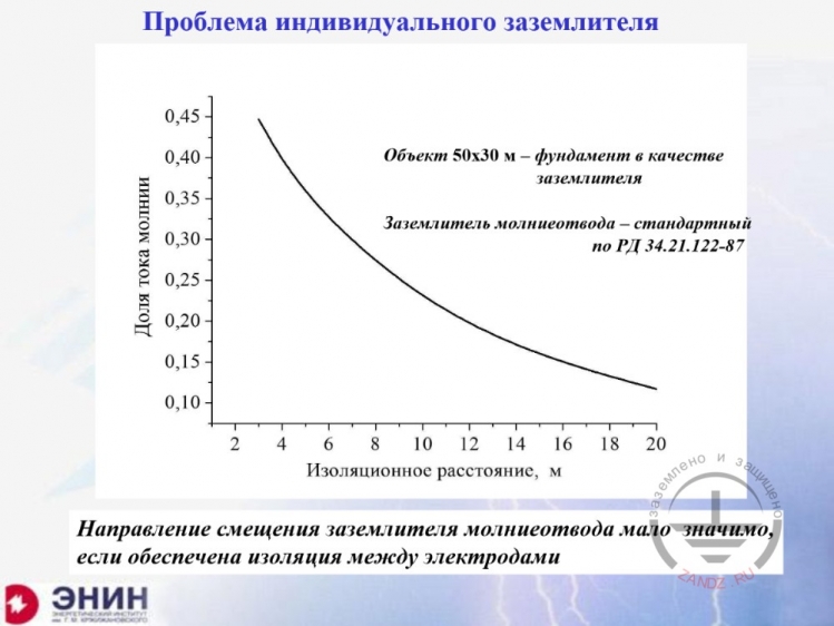
Problem of individual grounding device
Lightning current fraction
Facility of 50 x 50 m; the foundation is used as the grounding device
The grounding device of the lightning rod is standard as per RD 34.21.122-87
Isolation distance, m
The displacement direction of the grounding device of the lightning rod is not significant if the isolation is provided between electrodes
— And now, one more question. I am going to spend about 10 minutes to answer it. You design a building. The customer comes to you and says, "I need a completely individual grounding circuit. The one that is connected to nothing. I need it to connect to a unique super-special equipment. Please make such grounding circuit." And now, the designer has to understand what the customer needs. Because there are two different tasks here. The first task is as follows: I have a building, the building has the foundation, which is used as a grounding circuit. The lightning rods are installed nearby, and they have their own grounding circuits. And I have to place these lightning rods at the distance so that the lightning current would not come into my grounding circuit from the lightning rods, and the foundation of the building is used as such grounding circuit. This is the first task. We often face this task.
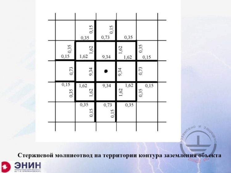
Lightning rod within the facility grounding circuit
Стержневой молниеотвод на территории контура заземления объекта - Lightning rod within the facility grounding circuit
— I have shown it before repeatedly. I have a grounding circuit for something, for example, this may be a grounding circuit for a large plant, an oil pumping company, or just a grounding circuit for a substation. And there is a lightning rod in the centre of the circuit. I have no other place to install it. This lightning rod has a typical grounding device. Now, I perform calculations to know what lightning current fraction goes to this grounding circuit. Look at the values in % for each bus. Here, the first nearest four buses gather 40% of the lightning current. But all adjacent buses are actually loaded with about 60% of the lightning current. It means that here we can no way create an isolated system, unless you bury this grounding device of the lightning rod deep into the ground with its complete isolation.
Hazards of a creeping discharge
Опасность скользящих разрядов
Заземлитель молниеотвода по РД 34.21.122-87
Rg = 0,085ρ Ом
Длина скользящего канала, м
Ток молнии 30 кА
Удельное сопротивление грунта, Ом м
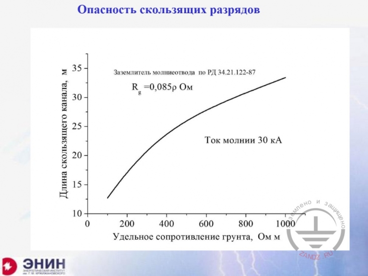
Hazards of a creeping discharge
The grounding device of the lightning rod is made as per RD 34.21.122-87
Rg = 0.085ρ Ohm
Creeping channel length, m
Lightning current 30 kA
Specific soil resistivity, Ohm·m
— The second task is quite different. The task is as follows: if I move the grounding device of the lightning rod far enough from the grounding circuit, there still exists danger of a creeping spark discharge from the grounding device of the lightning rod, which may reach the facility grounding circuit. The length of this creeping discharge is significant. Look here. I have a creeping discharge, and its length is calculated versus the specific soil resistivity for the typical grounding device of the lightning rod, which is recommended by regulatory document RD-34. In a "not so bad" soil with the specific resistivity of 400 Ohm·m the length is 25 meters. If you have a "worse" soil with 1,000 Ohm·m, then the length will be 35 m. And such channel is a metallic connection between two grounding devices. In order to avoid this, we need to design a special grounding device near the lightning rod, which would either eliminate such discharge generation, or direct it to the safe side. This is a special issue, which can be solved, but it is beyond our scope now.
Individual grounding device for unique equipment
Uиз/Ugr
Индивидуальный заземлитель для уникальной аппаратуры
Цель – исключить подброс потенциала на заземляющей шине?
Смещение вглубь
Контур заземления 50 х 50 м с ячейками 10х10 м
Смещение во внешнюю сторону
Изоляционное расстояние, м
Uis/Ugr
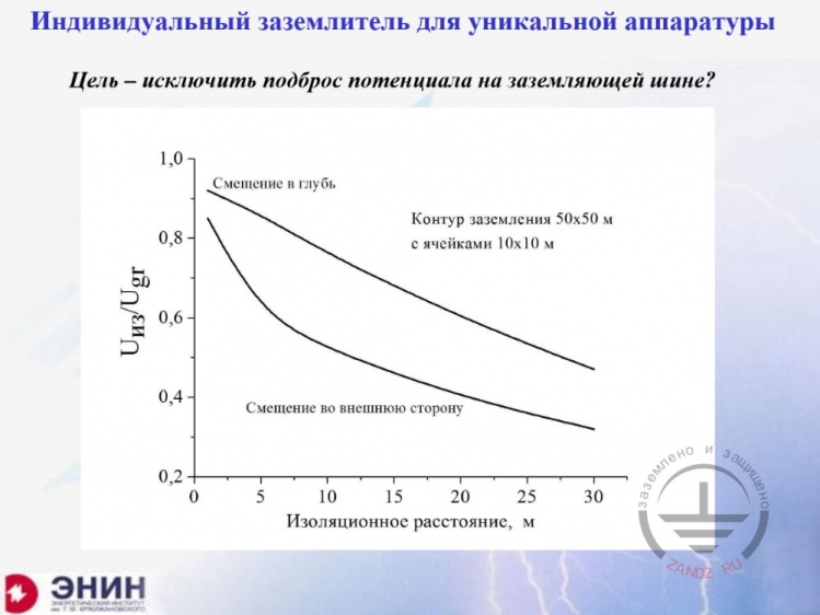
Individual grounding device for unique equipment
The aim is to prevent surge voltage at the grounding bus?
Inward displacement
The grounding circuit of 50 x 50 m with 10 x 10 m cells
Outward displacement
Isolation distance, m
— I have a grounding circuit. And I want to make a special grounding device near this grounding circuit, with its potential not increasing when the lightning current is distributed, e.g., through the building's foundation. It appears that it is very difficult to solve this task. This is because even if we use the isolation distance of 10 or 20 m, this individual grounding device's potential is tens of percent of the potential that occurs in the building's foundation. And it is almost impossible to create such an isolated grounding device. Therefore, the thing that we call a separate isolated grounding device is more of a fantasy than reality. It is because, in reality, whatever grounding device you install near your building's foundation, its potential will always be tens of percent of the building's potential. Unfortunately, there is no reason to talk about perfectly isolated grounding devices. It is what the situation like now. Here are the tasks the designers face, and these are the limits, within which these tasks may be solved. I am ready to answer the particular questions if there are any. Thank you very much for your attention.
Questions and answers
— Indira, do we have questions?
— Eduard Meerovich, thank you very much for the report. We have some questions. If you are ready, I can read them.
— I am ready.
— We will start with the question of the specific soil resistivity: "Tell me please, during calculations, can I take the specific soil resistivity measured in winter as a base?"
— If you measure the specific soil resistivity in winter, you will always obtain higher value than in summer. It is because the surface soil layer is frozen and due to this, the value you obtain is overestimated. You will not benefit from this. Do you understand? Because if you use this specific resistivity, but the actual value is always lower, then your work will be harder. I think it is not worth using it, because you make your own work harder. That is my answer.
— Eduard Meerovich, thank you for the answer. I have a question from Andrey Serochkin. The question is related to the top soil layer replacement regarding the example you described, at the Russia / Finland border. The question is as follows: "What soil was used instead of sand in the example at the Russia / Finland border? Was it black soil?"
— I can tell that. Loamy soil was poured with the specific resistivity of about 150 Ohm·m over the rocky soil.
— Andrey, I hope your question is answered. We will proceed to the next question then. The question is from Viktor Vasyukov. I read it: "Eduard Meerovich, I agree that it is expensive to replace the soil. I use Dolin's and Mankov's books, my colleagues use Shekhovtsov's book. How can I get your book?" This is the first question.
— Let me answer it right now. Here is Indira. She is the representative of the company that owns the entire book circulation. This book is being sold. I do not know the price of my book in this company. Do you understand me? Because I received my author's copies and I did not ask about the price. But I understand that it cannot be expensive in the company that spends so much money on advertising, such as the Grounding and Lightning Protection project at ZANDZ.com. I suppose it has a moderate price. You can easily get it by contacting them. I have no doubt in that.
— Yes, the book is available for sale. I will ask my colleague Dmitry to send a link to our website, where you can have a look at it and buy.
— You know, it is a good book. If you do not blow your own horn, no one will do it for you. But I tried to write it so that it would be useful for the designers, in particular. What is the second part of the question?
— Viktor asks the second question: "How to simplify the calculations of complex cellular grounding circuits with 5 x 5 m cell?"
— Look here. I have shown you the following thing intentionally.
— Thank you very much for your answer. Eduard Meerovich, there are also questions from Viktor: "If we have a requirement for the touch voltage (not exceeding 25 V or 50 V), but the resistance is not standardized, i.e., we can have 1 Ohm or 0.5 Ohm and use a lot of metal, respectively. What do you think, what resistance should we use? 1 Ohm, 4 Ohms?"
— No, the point is as follows. In order to design the grounding device for touch or step voltage, our EIC offers this opportunity. Although, it is almost never done in our country and you have to consider this fact. You will have to obtain information: at what particular current the touch voltage should be equal to this value.
— Eduard Meerovich, thank you for the detailed answer. We have more questions. Dmitry asks about the vertical grounding devices: "When can we use them? As it happens, it is worth using the vertical grounding devices only when we have low-resistivity soils and in the soil depth?"
— Precisely so. Well done! He got my thought correctly. That is the way I wanted him to understand it. Indeed, if you can reach the conductive soil with the vertical rods, it does make sense to use them. But if you have more or less homogenous soil, then the use of these vertical electrodes in addition to the foundation may reduce the grounding resistance within tens percent, 10, 20, 30; it is not worth doing it. But if you can reach the highly conductive soil or water, then go for it.
— Thank you, Eduard Meerovich. We have a question from Andrey: "Dear Eduard Meerovich, please give your advice on the current situation. One of the plant's building was rebuilt as a data processing centre with high-tech IIP equipment. It has already been commissioned. We observe some regular faults in complex automated and management engineering systems. We suspect that something is wrong with the grounding. Are there any efficient modern technologies to analyse such problems?"
— I understand. What can I say? There are companies in Russia, which analyse the electromagnetic environment in the territory of the technical facility. I am sorry, this is not an advertising, but one of the companies I can remember now is Moscow ELNAP. In scientific and technical aspects, it is headed by Ruslan Konstantinovich Borisov. He is a well-known specialist in pulse impacts in Russia. If you contact this company (and you can find it over the Internet) and you have enough money to order the analysis of the electromagnetic environment, they will perform such analysis and develop technical measures to protect against the interferences, if there are any. I think they will likely offer that you do not change the grounding, but create a local circuit protection using the overvoltage suppressors and shields. This company works with the issue willingly and hard. I think you can find other companies, but this one has come to my mind because we talked about it yesterday.
— Thank you, Eduard Meerovich. The next question from Dmitry: "Seasonal coefficient, is it some Mumbo Jumbo, or not?"
— Seasonal coefficient is nothing like Mumbo Jumbo. Seasonal coefficient is a normal tool, but the point is as follows. You know, it is like this. I think that Mumbo Jumbo is that you use one and the same coefficient for different grounding devices. I can explain this.
— Thanks for your answer. The next question: "What to do if the grounding circuit and the lightning protection system are one and the same device?"
— First, this is a normal situation, because our Electrical Installation Code (EIC) offers combining grounding circuits for various purpose into a single circuit. And there is no exception for the lightning protection in this regard. Therefore, using a common grounding circuit for lightning protection elements is an ordinary situation. It is a different matter when it is unacceptable due to any considerations. In this case, you need to take into account the points I tried to explain when I was speaking about individual grounding devices.
— Thank you, Eduard Meerovich. Oleg asks the question about combination of the protective grounding circuit and the lightning rod: "The equipotential bonding system recommends that you combine the grounding circuits of the protection system and the lightning rod. What about the dangerous voltage import?"
— The point is as follows.
— Thank you very much for your answer. Eduard Meerovich, here is the last question from Aleksey: "Dear Eduard Meerovich! STO Gazprom 2-1.11-170-2007, paragraph 4.9.1, "Freestanding lightning rods and each support of freestanding lightning groundwires should have the grounding resistance of not more than 10 Ohms for the facilities of the first and the second lightning protection categories, and not more than 20 Ohms for other categories. Is this norm applicable to the combined (repeated and lightning protection) grounding, for example, of a gas distributing plant?"
— You know, the situation is as follows. By the way, I do not remember 20 Ohms there. I believe the value of 10 Ohms is used there for the first category. However, the situation is as follows. If you have a company standard and it does not contradict the state standards for the worse, you should use the standards that are approved in the industry. I thought it was 10 Ohms for the first and the second categories, but in the soils with the specific resistivity of more than 500 Ohm·m this value could be increased but to 20 Ohms at most. As far as I remember this standard, it says like this. But you should design in accordance with the standard, because this standard is mandatory for your industry, if it does not contradict the Russian standard for the worse. And it does not.
— Thank you, Eduard Meerovich. Aleksey made a remark that the value was 10 Ohms.
— 10 Ohms, right? You should follow the standard. There is nothing more you can do.
— Thank you very much. Please ask more questions, if you have any.
— Well, I have to say good-bye and thank the participants for taking part in the seminar. I am generally pleased, especially when hardball questions are asked. Do you understand me? It is because you feel that people are masters of their subject, they are interested in it and it is essential that the real work connection appears between what you speak about and what the people will do in their practice. Regarding the calculations of the grounding circuits, especially when it comes to calculations of step and touch voltage, which are always confusing. I think that our Russian specialists must forget about the abacus, sliding rulers, or even calculators in their smartphones. They definitely should use computers. It is not difficult to learn how to use the computer for calculating the grounding resistances. There are people in my generation, who have not previously seen a computer at all, but they mastered it easily, and I am among them. I deal with young people, so I think that all of you can learn how to do it rather quickly. Especially if the Grounding and Lightning Protection project at ZANDZ.com will start an initiative to help you in mastering these skills. Thank you very much for your attention, once again! Best regards!
— Eduard Meerovich, we have the last question here. I will continue: if any questions are left without answer, send them to e-mail: info@ZANDZ.com. Unfortunately, the webinar time is limited. And the last question from Dmitry: "The soil located below the depth of freezing becomes more low-ohmic in winter than the top (freezing) layer automatically. Does it mean that the use of the vertical grounding devices is feasible in any case and any place where winter comes?"
— You know, not always and not in all sites. Send this question officially and I will try to answer it. You know, the point is, if you take a large grounding circuit and you have a large production building, for example, 60 x 60 m. Here is your grounding circuit, and it is in the frozen soil. The foundation is frozen, but the current goes to the depth where almost no freezing present. So, if you add vertical electrodes there, you will see that the efficiency of such vertical electrodes is slightly higher than that I have shown, but it will not be significant. But if your circuits are small, then you are correct in this case. I make a hole in this frozen soil and reach the soil that does not freeze and surely achieve the effect. This effect is sometimes significant, but it is true for small grounding circuits only. That is why even in moderate climates, if you know, the depth of freezing is about 1.5 meters. Do you understand me? It is not very deep. That is probably it. Thank you!
— Eduard Meerovich, thank you very much for the report. I think we can finish now.
— Best regards! Good-bye!
— Best regards! Dear colleagues, let me remind you that the videos of the previous webinars are published at ZANDZ.com and are available for watching for all authorized users. This webinar video will be published later, within two weeks. We will inform you about this in the news by announcing at ZANDZ.com. I will also copy the link to the videos in the chat. New webinar video will also appear here. Thank you for your participation. Best regards and see you at the next event.
Do you still have any questions? Send them to our technicians and you will receive detailed and reasoned answers.
<< Previous Page
Slides 6 to 10
Related Articles:
 Lightning Protection of Large Territories: Parks, Grounds, Plant Territories. Page 1
 Lightning Protection of Large Territories: Parks, Grounds, Plant Territories. Page 2
 Lightning Protection of Large Territories: Parks, Grounds, Plant Territories. Page 3