The sixteenth webinar of the "Grounding and Lightning Protection: Issues and Problems in Design" series
Webinar text. Page 2
How do we know the specific soil resistivity?
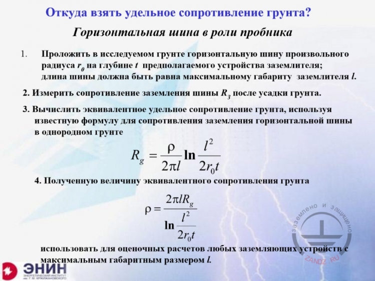
Откуда взять удельное сопротивление грунта?
Горизонтальная шина в роли пробника
Проложить в исследуемом грунте горизонтальную шину произвольного радиуса r0 на глубине t предполагаемого устройства заземлителя; длины шины должна быть равна максимальному габариту заземлителя l.
Измерить сопротивление заземления шины Rз после усадки грунта.
Вычислить эквивалентное удельное сопротивление грунта, используя известную формулу для сопротивления заземления горизонтальной шины в однородном грунте
Полученную величину эквивалентного сопротивления грунта
использовать для оценочных расчетов любых заземляющих устройств с максимальным габаритным размером l.
How do we know the specific soil resistivity?
Horizontal bus as a sample
1. Lay the horizontal bus of random radius r0 in the soil under study at the depth t for the proposed grounding device; the bus length must be equal to the maximum dimension of the grounding device l.
2. Measure the bus grounding resistance RG after the soil setting.
3. Calculate the equivalent specific soil resistivity using known formula for the horizontal bus grounding resistance in a homogenous soil.
4. Use the equivalent specific soil resistivity
in the estimates of any grounding device with the maximum dimension l.
— I would like to draw attention to one more point. Both Laurent formula and the formula used in our standards for calculating the grounding resistance comprise a specific soil resistivity as their parameter. How do we know the specific soil resistivity? Especially since you understand well that if you design a large grounding circuit, you need to know some averaged value, which should be used in this formula.
Vertical rods effect
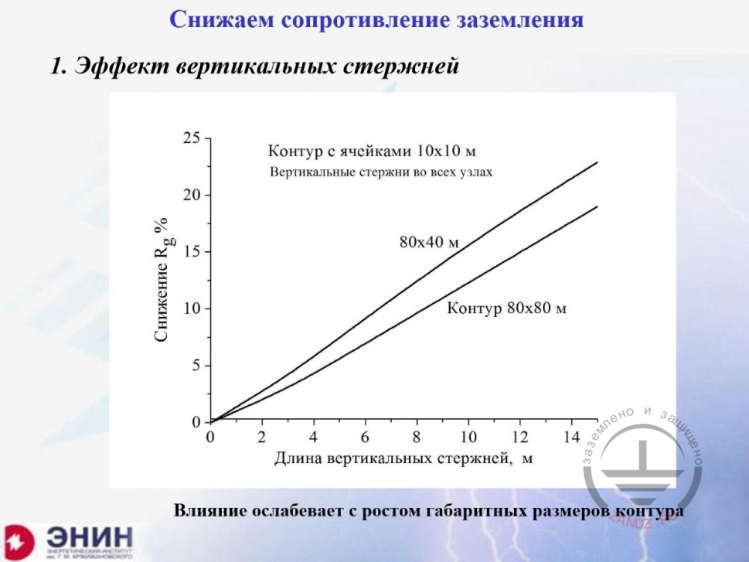
Снижаем сопротивление заземления
Эффект вертикальных стержней
Снижение Rg %
Контур с ячейками 10х10 м
Вертикальные стержни по всех узлах
Контур 80х80 м
Длина вертикальных стержней, м
Влияние ослабевает с ростом габаритных размеров контура
Reducing the grounding resistance
1. Vertical rods effect
Reduction in Rg %
Circuit with 10 x 10 m cells
Vertical rods in all nodes
Circuit of 80 x 80 m
Vertical rods length, m
The influence weakens along with the circuit dimensions increase
— There is another issue. The issue is as follows. You have done everything: built the foundation, measured the grounding resistance. And now you see that the grounding resistance you obtained does not suit your purpose. For example, you need 4 Ohms, but you obtained 12 Ohms. You have to do something with it. You have to do something either with the grounding circuit, or with the soil, because you cannot deliver the work like this. And the first thing that comes to your mind is: "Let us drive in vertical rods for this circuit!" And we will obtain what we need with these vertical rods. Therefore, the following question arises: what should we expect from vertical rods? You should necessarily evaluate the technical capabilities you have. In order to demonstrate the efficiency of vertical rods, I will show you the example. I have two grounding circuits. One grounding circuit is 80 x 40 m. It is a foundation of an administrative building with large dimensions. And here is another one, 80x80 m. It is a large production shop. Now, in each intercrossing of the buses in this circuit, I am going to drive in vertical rods. Their lengths are shown here, in the x-axis. The y-axis shows percentage values of the grounding resistance decrease when we use the rods I am driving in. Look here. With the typical rod length of 10 m (and it is hard enough to drive in longer rods in the soil), the grounding resistance change will be within 10 to 15% only. It is almost impossible to obtain any serious results for the formed grounding circuit with the vertical rods. You will use much metal and spend much money but obtain the effect of 10 to 15%. Do you understand me?
Circuit around the foundation
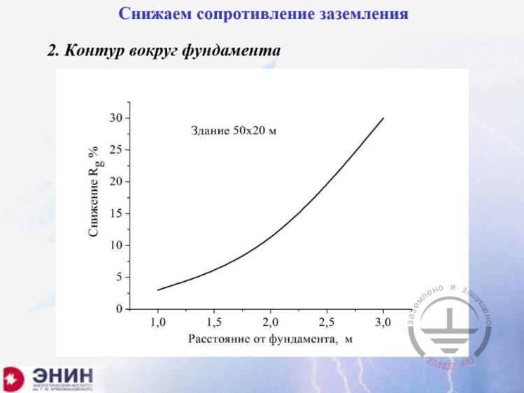
Снижаем сопротивление заземления
Контур вокруг фундамента
Снижение Rg %
Здание 50х20 м
Расстояние от фундамента, м
Reducing the grounding resistance
2. Circuit around the foundation
Reduction in Rg %
Building of 50 x 20 m
Distance from the foundation, m
— Now, when we know that it is not very efficient, I am going to discuss another recommendation that is widely used in the literature sources.
Replacing top soil layer
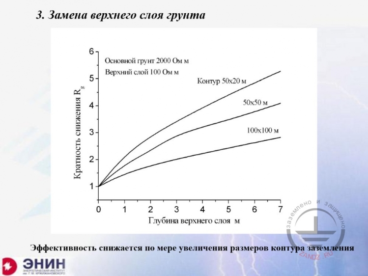
Замена верхнего слоя грунта
Основном грунт 2000 Ом м
Верхний слой 100 Ом м
Контур 50х20 м
50х50 м
100х100 м
Кратность снижения Rg
Глубина верхнего слоя м
Эффективность снижается по мере увеличения размеров контура заземления
3. Replacing top soil layer
Base soil 2,000 Ohm·m
Top layer 100 Ohm·m
Circuit 50 x 20 m
50 x 50 m
100 x 100 m
Reduction rate Rg
Top layer depth, m
The efficiency decreases along with the grounding circuit dimensions increase
— I have taken a step further. Since these simple means do not work, let us change the soil resistivity. This kind of work is performed quite often. The soil with higher conductivity is used by either pouring it over the base soil, or by transporting it by trucks, or by using a dredger. And now I want to understand the result that can be achieved this way. Certainly, the effect will be more significant here. Look. I have taken the 5-storey building of 50x20 m again. And I place the soil in this building's surroundings. And this is the depth of the soil I pour. The base soil, which is a "bad" soil with the specific resistivity of 2,000 Ohm·m, is a dry sand. And then I pour a "good" soil with 100 Ohm·m. If I pour a three-meter deep soil layer, then I will be able to reduce the grounding resistance by four times. Can you see? And that is really worth thinking about. I have seen these works performed in a large scale. For example, I have seen the territory near Russia and Finland border, where vast territory of about 1 km2 was poured with such soil at the depth of about three meters in order to reduce the grounding resistance. But, in fact, there is a limitation: the more your building dimensions... you see, I am increasing the building dimensions... you can see that the effect becomes poorer. But even for very large buildings of 100x100, the three-meters depth of soil allows reducing the grounding resistance by about two times. Surely, this is an expensive operation, but you can hardly think of anything else in such situation.
Deep-driven earth rod
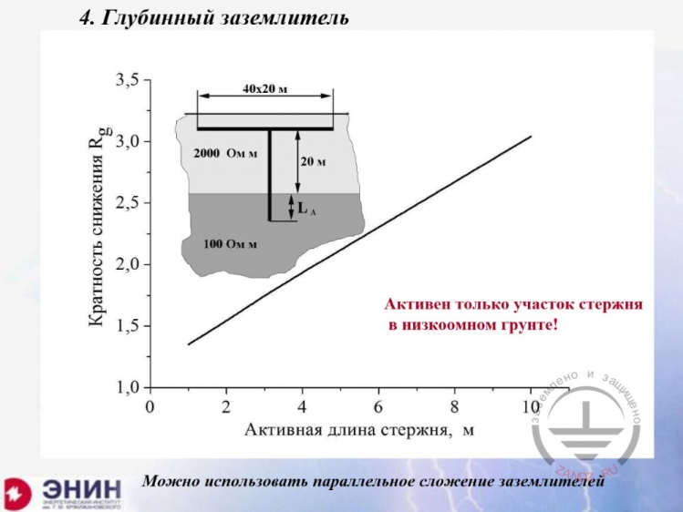
Глубинный заземлитель
Кратность снижения Rg
40х20 м
2000 Ом м
20 м
100 Ом м
Активен только участок стержня в низкоомном грунте!
Можно использовать параллельное сложение заземлителей
4. Deep-driven earth rod
Reduction rate Rg
40 x 20 m
2,000 Ohm·m
20 m
100 Ohm·m
Only the rod section placed in the low-ohmic soil is active!
The parallel summation of grounding devices may be used
— This time, I am going to consider another typical situation, which is often described in many different guidelines. Deep-driven earth rod. For example, I have the foundation of the building of 40x20 m, again. It is placed in a "bad" soil with the specific resistivity of 2,000 Ohm·m. I drive in a vertical electrode in order to reach the highly conductive soil. For example, I want to reach ground waters. Their specific resistivity may be 100 Ohm·m or 50 Ohm·m. I want to reach them.
<< Previous Page
Slides 1 to 5
Next Page >>
Slides 11 to 14 + questions and answers
Related Articles:
 Lightning Protection of Large Territories: Parks, Grounds, Plant Territories. Page 1
 Lightning Protection of Large Territories: Parks, Grounds, Plant Territories. Page 2
 Lightning Protection of Large Territories: Parks, Grounds, Plant Territories. Page 3