The sixteenth webinar of the "Grounding and Lightning Protection: Issues and Problems in Design" series
(was held on February 1, 2017 at 11:00)
Full screen "720p" mode is recommended
The work always starts with analyzing the properties of soil where the structure to be designed will be installed. The source data required for this are recommended to obtain by vertical electrical sounding, which is a troublesome and not quite accurate operation. A natural question arises here: "Can we avoid it?" We may say "Yes", if we rely on fair views regarding the penetration depth of the current flowing from the grounding electrodes into the soil.
The second question, which is as important as the first one, relates to the test check of the grounding resistivity. Regulatory directions are quite certain about that. Unfortunately, they are almost impossible to implement, if the facility to be designed is located in urban or industrial area, where we do not have much free space. The engineering solution exists, however, and it is readily implemented in the majority of practically significant situations.
The Russian regulatory documents reasonably recommend using the reinforced concrete foundation for the structure to be designed as a natural substitute. In this regard, the third question arises: "How to correctly estimate the foundation grounding resistance and what to do if it exceeds the allowable level significantly?" Now, we have to estimate the performance of additional grounding electrodes, replacing the top soil layer with more conductive one, and using reactive electrodes. Even though the methodological base of these issues is detailed enough, it is not always used in design evaluations properly.
Finally, once again, we have to turn back to evaluating the prospects of creating a fully individual grounding device, which is securely protected from the external currents penetration into the device. The arrangement of such grounding device is extremely costly. Therefore, we have to be completely sure that it is necessary.
Webinar text. Page 1
Estimated reading time: 50 minutes.

Designing Grounding Devices
ПРОЕКТИРУЕМ ЗАЗЕМЛЯЮЩИЕ УСТРОЙСТВА
Семинар шестнадцатый
Проф. Э.М. Базелян
ОАО «ЭНИН» Москва
DESIGNING GROUNDING DEVICES
The sixteenth seminar
Prof. E.M. Bazelyan
OAO ENIN, Moscow
— Today, we are going to continue the webinar series for the designers. This is the first webinar conducted this year and the sixteenth one in the webinar series for the designers. The series continues. In order to avoid missing anything I propose that you register for all webinars at once by filling in only one form at our site. I am going to send you the link in the chat now. Please follow the link and register. At ZANDZ.com and in our communities in social media, you may receive information about our new events and series, which are prepared for you this year. I will also send you the link to our community in the chat. Join our groups and get information about new events. So, let us proceed with the today's webinar. Today, we will discuss common questions that arise during the design of a grounding device. In particular, we will discuss the analysis of soil properties, control check of the grounding resistance, individual grounding device, and many other. Dear participants! Please join the discussion, ask your questions and make comments. The webinar will take about 60 minutes. The questions will be answered at the end of the webinar. If required, it will be performed on an ongoing basis. At that, my welcome speech ends. The turn is passed to our lecturer. Hello, Eduard Meerovich.
— Good afternoon! Good afternoon, dear seminar participants. This is our first seminar, indeed. Actually, we compose kind of "The Arabian Nights", because this seminar is a sixteenth one. However, to make sure that our series is really like "The Arabian Nights" book, now we have our Shahrazad here. Her name is Indira. I hope that it will be more exciting to work together with her. I hardly agreed to take part in this seminar, because when we talk about grounding devices, such an enormous number of different local questions arises, which are hard to answer at once. And the most important point is: it is hard to make answers specific, because design calculations of the grounding devices require special training. But you definitely can do the following thing.
Two global designer's issues
Два глобальных вопроса:
Что можно сделать, если заданы -
- 1. Длина заземляющей шины?
- 2. Площадь заземлителя?
1. Эффективное использование заземляющей шины
Вертикальный стержень
Горизонтальная шина
Радиус электрода 10 мм
м-1
Горизонтальная шина
Вертикальный стержень
Длина электрода, м
Сетка из шины длиной 1000 и с размерами 106,4х42,6 м
Rg = 0,00656ρ Ом вместо 0,00282 Ом
!!! Трехкратное увеличение сопротивления заземления !!!
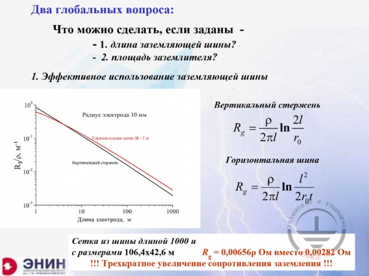
Two global issues:
What can we do if the following parameters are set:
- 1. The grounding bus length?
- 2. The grounding device area?
1. Efficient use of the grounding bus
Vertical rod
Horizontal bus
Electrode radius is 10 mm
m-1
Horizontal bus
Vertical rod
Electrode length, m
Bus grid 1,000 long and with dimensions of 106.4 x 42.6 m
Rg = 0.00656ρ Ohm instead of 0.00282 Ohm
!!! Threefold increase in the grounding resistance !!!
— You can consider general problems, which occur in the course of design. In addition, you can have a look at what tools the designers may use in the course of their designing work. What are the first two major issues? You have a grounding resistance to consider in the design. Now you have two ways: either you provide this grounding resistance, while spending as few materials as possible, and minimize the electrodes to be driven in the ground; or your second option is: you have a very limited area and you cannot go outside the area, and you must do the best within the area you have. The designer may face both problems depending on the situation. First, I will try to start with the question: what can you do when you have what you have? The question is as follows: how to arrange the grounding electrodes if you have to minimize their lengths? You do not have many options here. Either you place this electrode horizontally, or you drive it in vertically. Although, in fact, it is usually not possible to drive it in the soil for deep depth. If you drive it in vertically, the grounding resistance is determined by the well-known formula. It is almost perfectly accurate. Its error is less than 1%. If you place the electrode horizontally, the calculation formula is quite similar. In this formula, only one component that is additional to the electrode length appears: in addition to the electrode radius, the depth from the ground surface is added, at which the electrode is embedded in the soil. I.e., the depth of the trench where you place such horizontal bus. If you calculate by using one formula and another formula, then you will receive two such length dependences, wherein they are almost identical. I.e., you will not gain too much by placing the electrode either horizontally or vertically. The grounding resistance will be almost the same. And this is a minimum of what can be done. What kind of minimum is it? Now, I take the bus of 100 meters long. Look here: I have the grounding resistance to the specific soil resistivity ratio of 10-2. What does it mean?
What will happen over time?
Что будет в динамике?
ρ = 200 Ом
Шина длиной 1000 м
Сопротивление заземления, Ом
Время, мкс
Но сокращение габаритных размеров заземлителя при тех же затратах металла ведет к росту сопротивления заземления
Протяженные электроды плохо работают при импульсном токе с крутым фронтом!
ρ = 200 Ом м
Сетка ~ 100х40 из шины 1000 м
Время, мкс
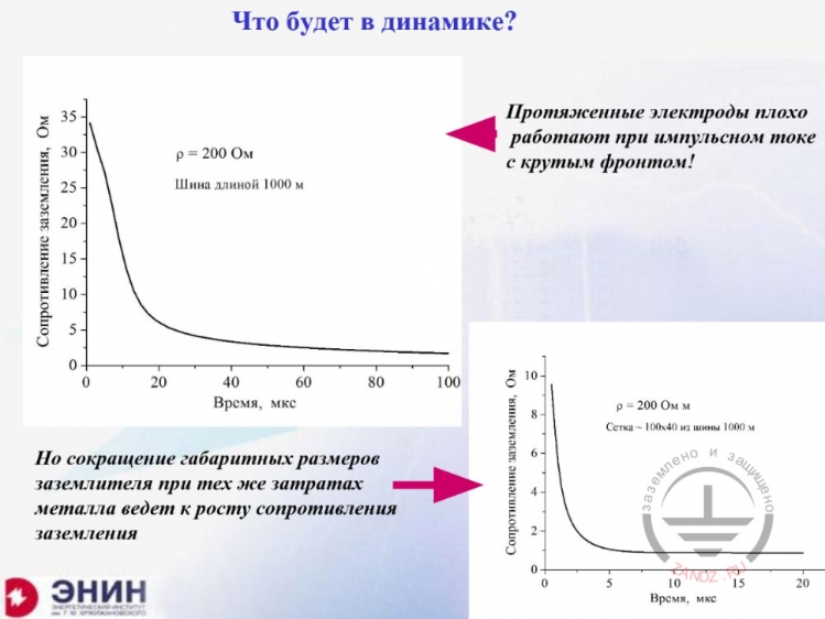
What will happen over time?
ρ = 200 Ohms
Bus 1,000 m long
Grounding resistance, Ohms
Time, mcs
But reducing the grounding device dimensions with the same metal inputs leads to the grounding resistance increase
Extended electrodes function poorly when the pulse current has a steep frontline!
ρ = 200 Ohms·m
Grid ~ 100 х 40 made of bus of 1,000 m long
Time, mcs
— The point is that all these resistance values shown relate to constant and slowly changing current of industrial frequency only. But if you have pulse currents (and we use pulse currents only in the lightning protection), then there is no benefit in making straight and lengthy bus, because, if you make such bus, it will be putting into operation for a long time. This diagram shows how the horizontal bus of 1,000 m long puts into operation, as if someone would have decided to install it into the soil. Look: if I take 10 mcs (and it is a typical time for the lightning frontline), then the resistance of such bus will be 25 Ohms, while, in the stationary mode, it was only 2 Ohms. In view of the fact that the bus is very slow in putting into operation in the pulse mode and its resistance is at least by an order of magnitude higher that in the stationary mode, this will prevent you from making the extended, lengthy grounding electrodes. However, if I make the grid out of this bus, which has been discussed above, you can see that in 10 mcs, the grid will almost have the grounding resistance of the stationary mode. I.e., it is reasonably to construct the straight, lengthy bus only in the case when you are not worried about the pulse mode of current flowing; if the buses are not for the lightning protection. But if they are, you should make some compact device. The second point now.
Grounding device in a limited space
2. Заземлитель на ограниченной площади
Площадь под заземлитель DxD
Глубина заполнения металлом
3 м 5 м 10 м 20 м
Rg/ρ, м-1
D, м
Слабая зависимость от длины вертикальных электродов! (в основном работает площадь контура заземления)
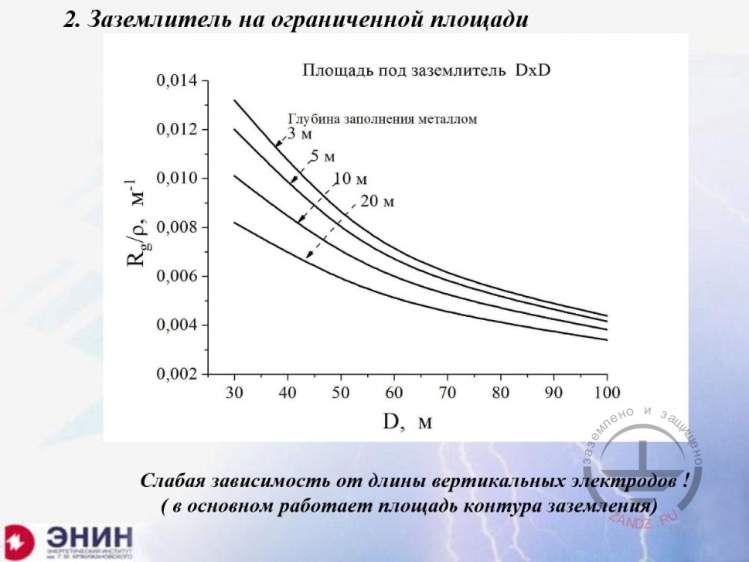
2. Grounding device in the limited area
Area for the grounding device D x D
Metal-filling depth
3 m 5 m 10 m 20 m
Rg/ρ, m-1
D, m
Poor dependence on the vertical electrode length! (primarily, the grounding circuit area works)
— The second point is as follows: what if I have a limited area? I can use as many sleeve pipes and electrodes as I need, but the area is limited. And I can only work within this territory. This is a typical example of building an administrative, industrial, or civil structure. Its reinforced concrete foundation is used as a grounding circuit. I cannot go beyond the foundation, because I am in the city, in the urban area, and I cannot do anything more or place anything else. What kind of situation is this? Look here. I have plotted a series of estimation curves, which demonstrate that the grounding resistance depends on the size of the square territory, say, 10 x 10 m, 20 x 20 m, or 50 x 50 m. If the foundation goes to different depths, for example, 3 meters, this is the uppermost curve. Look, for a typical structure of 50 x 50 m (industrial shop) I have the grounding resistance to the specific resistivity ratio of about 0.01. If I multiply this value by the specific soil resistivity of 100 Ohm·m, then I will obtain 1 Ohm, which is the perfect grounding resistance suitable for any electrical engineering company. But if I use the same grounding circuit in the "bad" soil, for example, in the soil with the specific resistivity of 2,000 Ohm·m, then I will obtain 20 Ohms However, 20 Ohms will not be suitable for any electrical engineering company. I cannot go beyond the foundation. What can I do?
How to estimate the circuit grounding resistance?
Как оценить сопротивление заземления контура?
ГОСТ 12.1.030-81
Формула Оллендорфа-Лорана
S- площадь контура заземления, L – полная длина электродов
Длина сетки 100 м
Длина сетки 100 м
Формула из ГОСТ
h=5 м
h = 10 м
Компьютерный расчет
Ширина сетки, м
Расчет по средней плотности тока
Формула Оллендорфа-Лорана
Компьютерный расчет
Ширина сетки, м
Трудно придумать что-то лучшее, чем полевой расчет
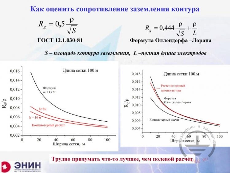
How to estimate the circuit grounding resistance?
GOST 12.1.030-81
Ollendorf — Laurent formula
S is the grounding circuit area, L is the total electrode length
Grid length 100 m
Grid length 100 m
Formula from GOST
h = 5 m
h = 10 m
Computerized calculation
Grid width, m
Calculation with the average current density
Ollendorf — Laurent formula
Computerized calculation
Grid width, m
It is hard to invent something better than field calculations
— And there is another question: how to estimate the grounding resistance during design calculations? Looks like the single extended or vertical grounding devices are our fantasy. After all, usually you have to form the grounding circuit, and the foundation is typically used as such circuit. What can you do to estimate within several seconds? We have 2 formulas, which are recommended for use in our different guidelines. The first one is written here. Please have a look at it. This formula employs two parameters only: the specific soil resistivity and the area of the foundation that is used as a grounding circuit. Alternatively, this may not be the foundation area, but the circuit area as a grid you are designing. If I use this formula for estimation, then it will probably be too high. Why? It is because, in this formula, I did not take into account the vertical electrodes that exist. For example, it also has its foundation, the depth angles, and such penetration is not considered in this formula in any way. For this reason, calculations based on this formula when using actual values give an error, which results in over-estimation of the grounding resistance. But if you do not have any other option, then, surely, you can use this formula for rough estimating. There is another formula in the foreign literature sources, which is called the Ollendorf — Laurent formula. Generally, the structure of this formula is almost the same as of the previous one. Look, here we use virtually the same ratio of 0.44 instead of 0.5, the same specific resistivity, and the same square root of the foundation area. But we have an addition here, which is the specific resistivity divided by the total electrode length. This adjustment is not really significant. It considers a small fraction of the vertical electrode impact, but it is not much considered, because, in fact, there is a difference between the Laurent formula and accurate calculations. Over-estimation errors of the grounding resistance are, again, at the order of tens of %, but if you have no other option then you certainly better use this formula than nothing. What should we use then? You should use field calculations. They allow calculating the resistance of any foundation. The “Grounding and Lightning Protection at ZANDZ.com” project has published the book, wherein the entire chapter contains the detailed description of this method. The book is called "Practical Lightning Protection Issues", and its seventh chapter is entirely dedicated to this calculation method. Who is this chapter intended for? This chapter is for the professionals familiar with computerized calculating. It cannot be done in any different way, and here is the reason why. Imagine the grid you made, the grounding circuit. You have a 100 x 100 m grid with the 10-m cells. That is why you have almost 10-meters long bus sections. You will have individual currents in these sections. And in order to calculate the current, you will have to make as many equations as many sections you have. The number will be 220 in this example. You can hardly solve the system of 220 equations using a sliding ruler or a calculator. But you can solve this task by using a typical computer application for about one-tenth of a second. What is my proposal? I propose the company thinks of arranging special sessions or developing a special online application, which can be used when you need accurate calculations. But, in my opinion, you cannot avoid computerized calculations in this situation.
Next Page >>
Slides 6 to 10
Related Articles:
 Lightning Protection of Large Territories: Parks, Grounds, Plant Territories. Page 1
 Lightning Protection of Large Territories: Parks, Grounds, Plant Territories. Page 2
 Lightning Protection of Large Territories: Parks, Grounds, Plant Territories. Page 3