Webinar text. Page 2
In addition to sorting by a certain parameter, we can also specify headings. Let's try to do the following: we have a parameter that is called a “System Name”. We will also add it and will see that the particular values are assigned to it. Then, we will do the following: first, we need to classify the equipment by the systems, and then by the name. It is easy. In the grouping sorting, we have several values, items, which we can sort. It means that, in the beginning, we choose “System Name”, then “Name”, and press OK. And the elements by systems are shown first. Unfortunately, we have elements without any systems, but they can be filtered out later. And now, I can place the “System Name” not at the side as a separate column, but, e.g., provide it as a heading.
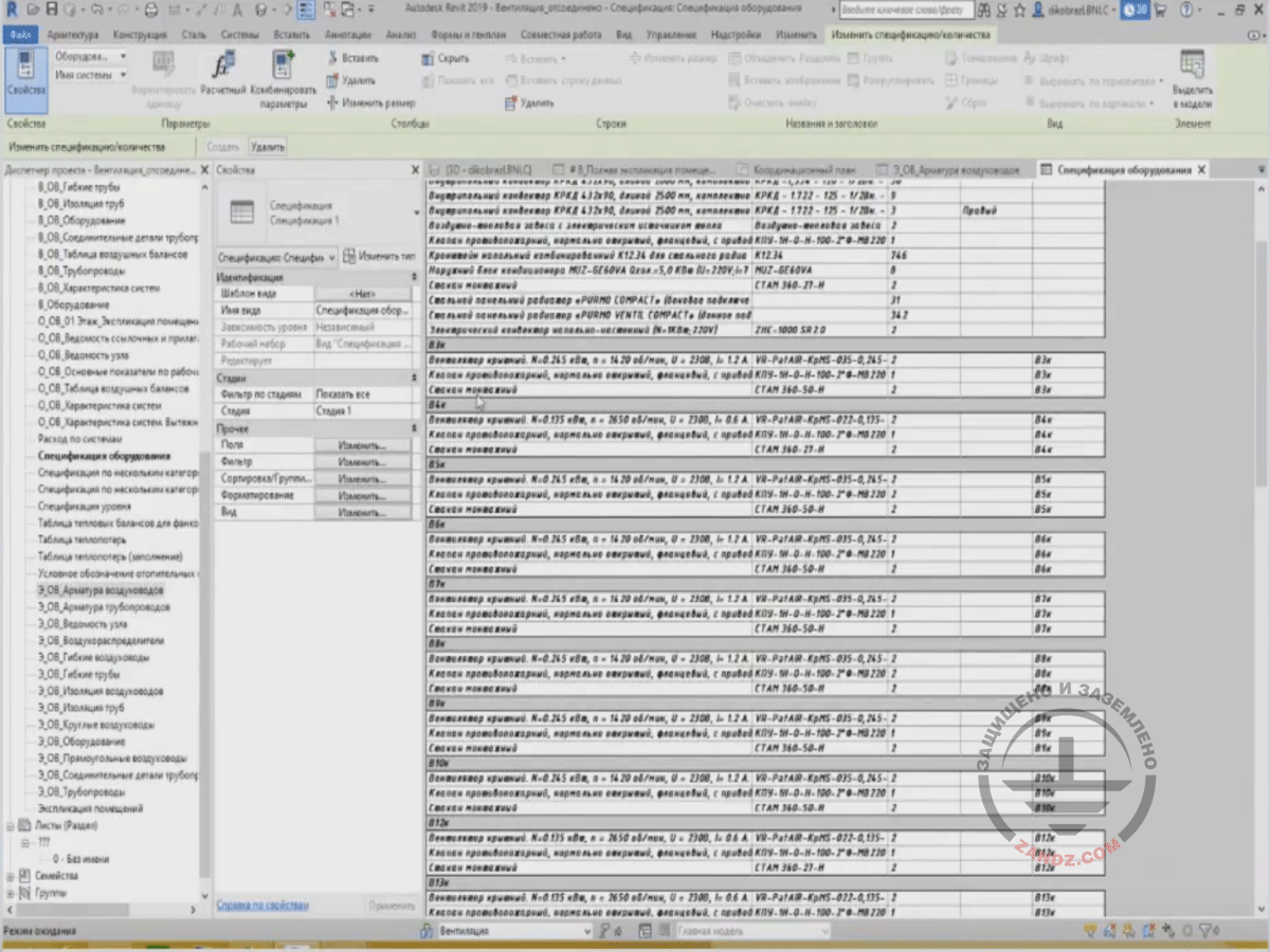
Demonstrating the heading creation process
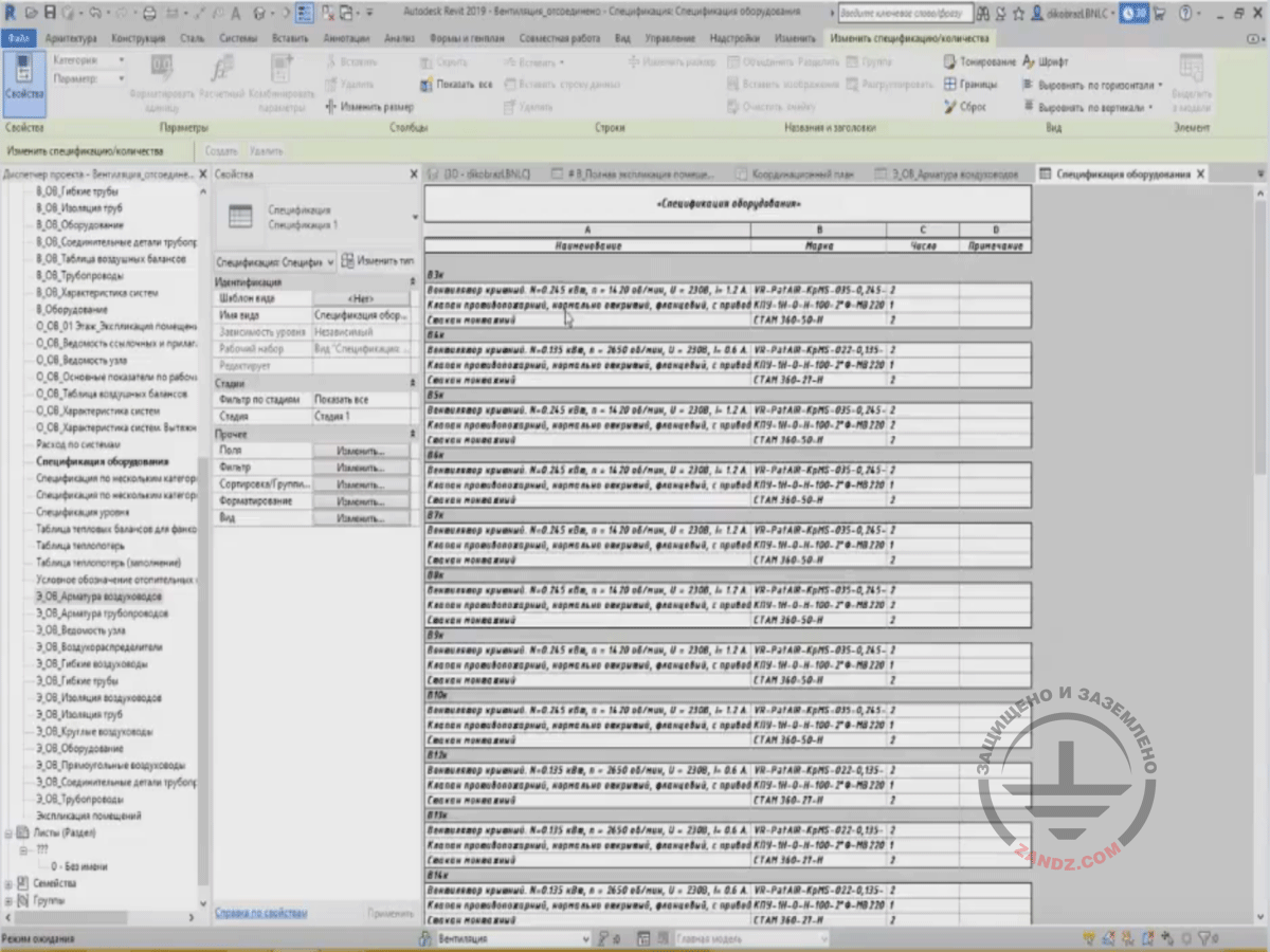
To create headings, I click the “Heading” tick opposite to the parameter in the area where the “System Name” is located, and then press OK. Now, each system with the particular set of equipment is located separately. For example, in the “V 3k” system, I have “Roof Fan”, “Valve”, and “Mounting Cup”. In the future, I will not need the “System Name” column, so I can hide it.
Creating headings in "Sorting/Grouping"
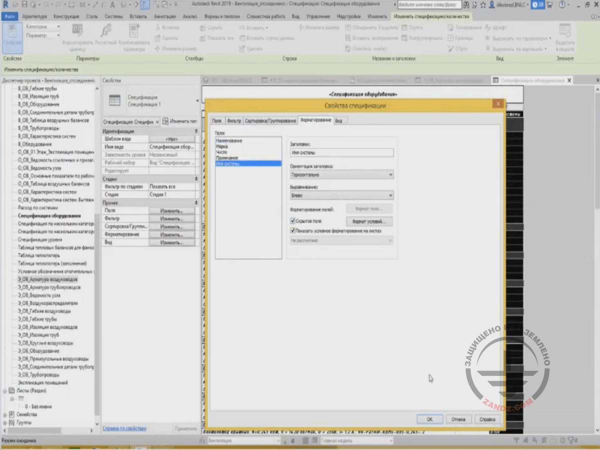
To hide a particular column, we go to the “Formatting” tab, choose a particular column and then press “Hidden Field”. The field has been hidden, but “Sorting/Grouping” by this parameters is still kept.
Hiding a particular column in a table
Then, in addition to sorting and grouping of specifications, we can use filters to remove extra elements. To do this, we can also choose particular parameters, and based on their values, we can hide some elements. What can we hide here? For example, the elements that have no "System Name" parameter, i.e. it is empty. I will just hide them. How can I do that? I choose the “System Name” parameter in filters and choose the empty value for "more", and then press OK. Thus, all parameters with the empty value for “System Name” are hidden now, and only those are left, which have the values for "System Name".
Hiding extra elements in filters
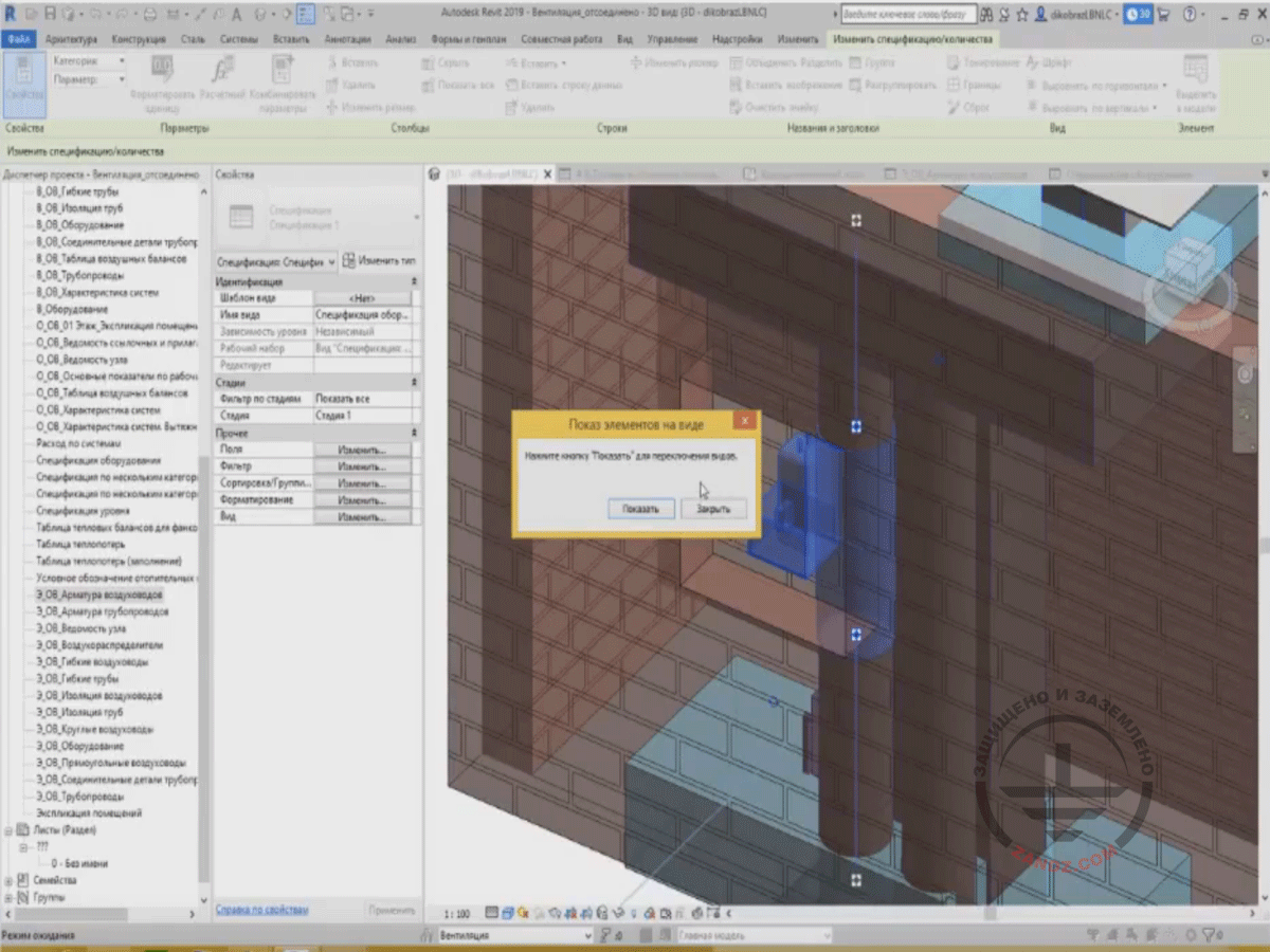
There is a good feature in specifications, i.e. when you highlight an element, the "Highlight in Model" button appears. So, if I press the button, Revit starts searching for the appropriate views, wherein this element is located and can be seen. I can then press the “Show” button, and it will switch the views until I find the suitable one. It can be well seen in the 3D view, so I can stop here. I press "Close".
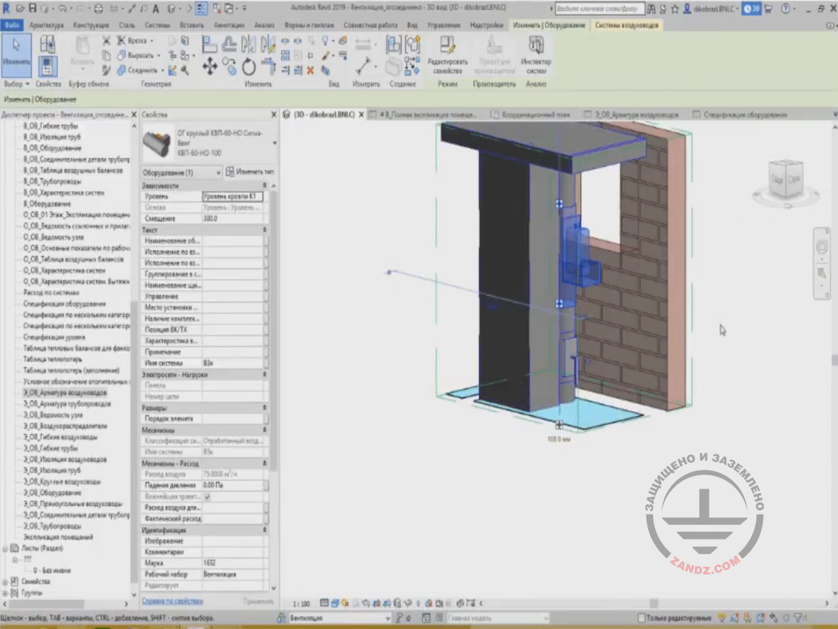
3D View
And this is the valve that was present in the Bill of Quantities. In future, for convenience, I can select it using a selection frame so that only this valve would be shown but not other elements. Such selection is made. It is great now. You can see where it is, view its parameters, characteristics, etc.
Demonstrating a valve
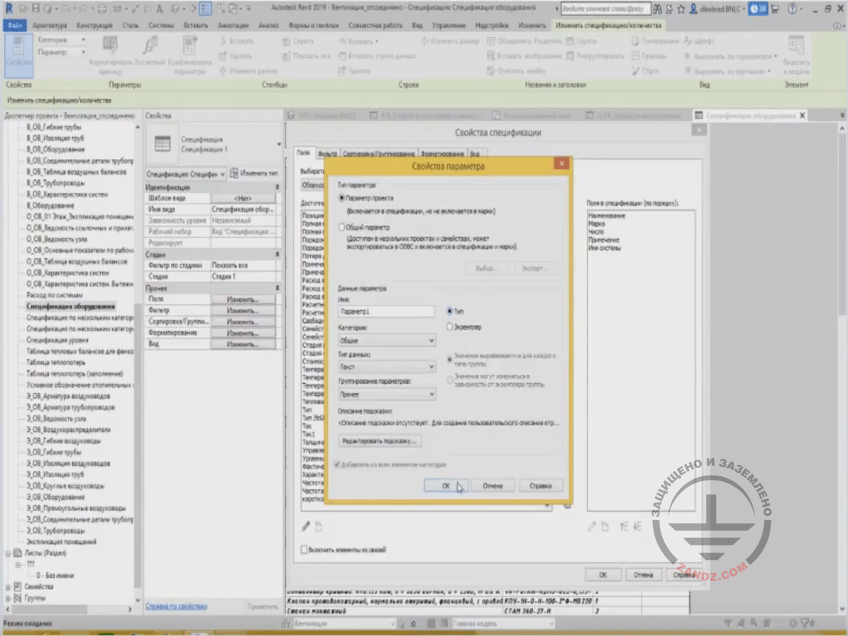
We will go back to the "Equipment Certification" table. In addition to sorting and filtering, we also have the so-called calculated parameters and project parameters. Certainly, we have many different parameters that can satisfy almost any needs of the designer working in Revit. But there may be situations when you need a new parameter for the Bill of Quantities. It can be added at any time. Let's add a parameter to our equipment table. I will not name it, I will just call it “Parameter 1”, and that's it. To do this, press the “Create Parameter” button in the “Fields” tab. A window appears, where I can enter the name for the parameter, i.e. simply “Parameter 1”. Then I choose what category it will belong to and what data type will be entered. Let's make a text parameter that will show some attributive information for our equipment. We choose “Data Type” — “Text”, and we add it to “Other” in “Grouping”.
Calculated parameters and project parameters
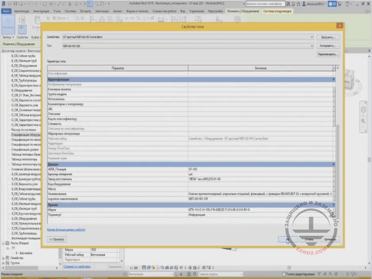
Here is my valve that was highlighted before. Where has the parameter appeared now? Since I have defined the type parameter, then this parameter will be used in the type properties in the window. We can go down and see that in the "Other" section, I specified that my parameter will be located in this section. "Parameter 1" is shown here. I can enter certain information regarding my element. For example, let's just enter “Information” and press OK.
Demonstrating "Other" section
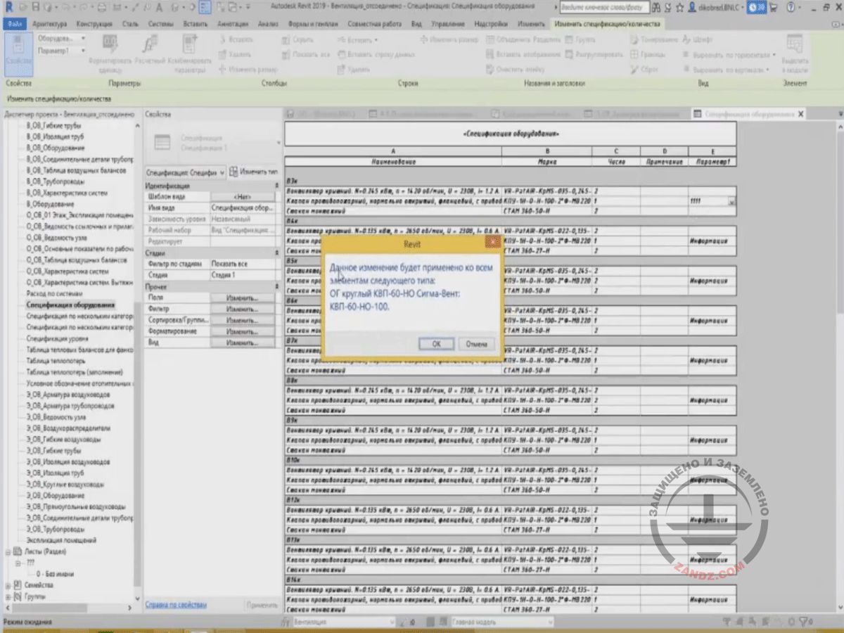
What can we see? If I go to the equipment specification, then you can see that, in each valve of this type, and there are many of them. This is the same valve, but they are located in different systems. The information on this valve has appeared. Moreover, I can change this information from the table; let's enter values. Since this parameter is a type parameter, then Revit says that the change will be applied to all elements of the following type. This type is written here, and after pressing OK, I can see that all of these valves have changed this parameter value to "1111".
Changing information in the table
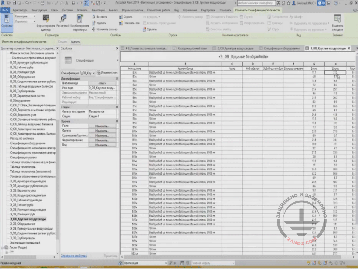
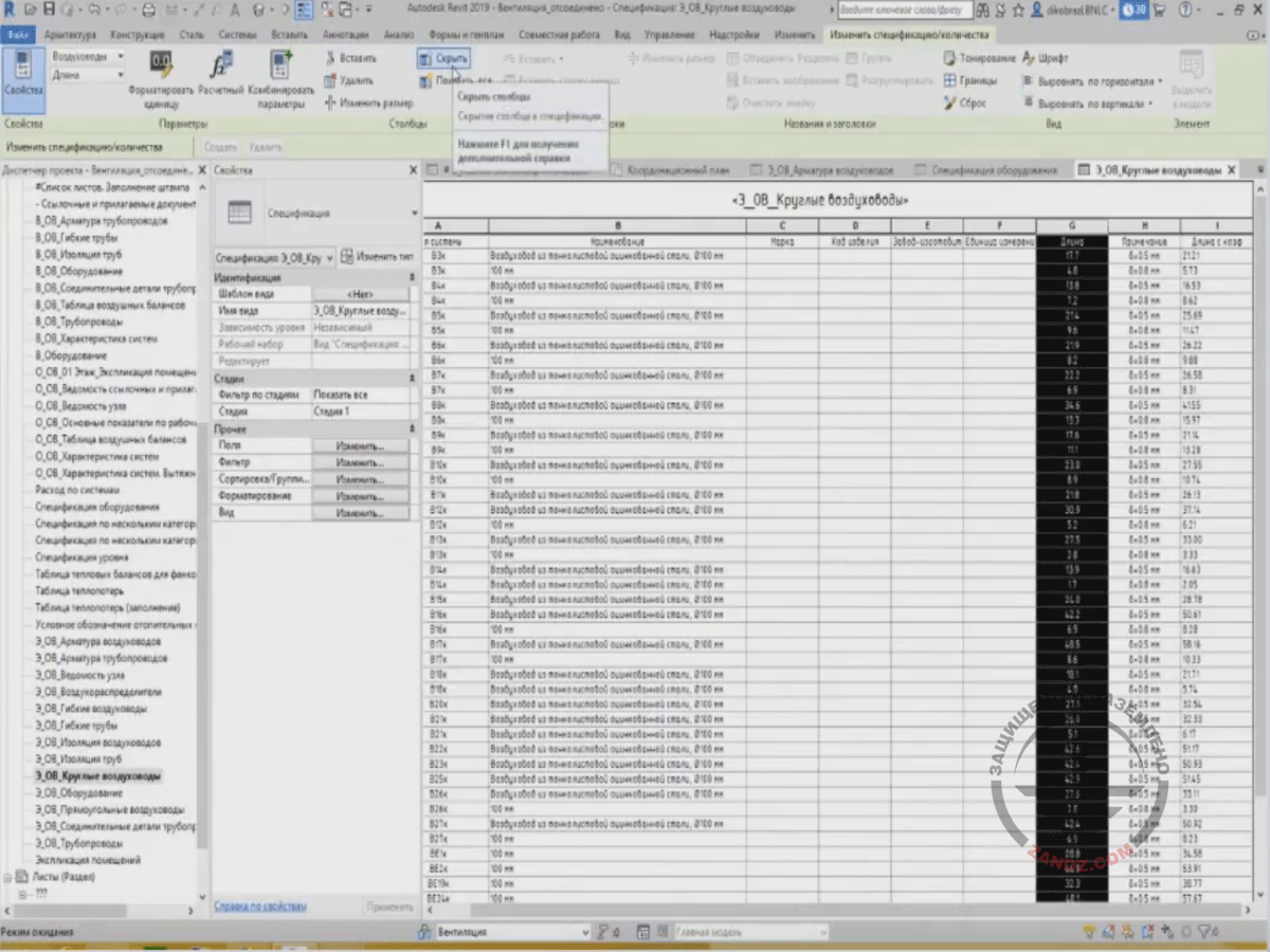
Let me continue. In addition to the parameters that can be created, we can also create the so-called calculated values. What are the calculated values and what are they needed for? For example, we have a specification for air ducts containing the parameter of the air duct length. And it is clear that Revit calculates the total length that is present in the project. But for purchasing, you may need an increase by several percent of the length, e.g., by 10%. So, Revit cannot change a certain value. The calculated values are created for this. Let's consider this option using air ducts. We choose the ready-made Bill of Quantities titled “Circular Air Ducts”. We have a table for the air ducts. It contains the column specifying the length. Let me show you the name of headings “Length”. We have the length parameter, and this is the actual length.
Creating calculated values
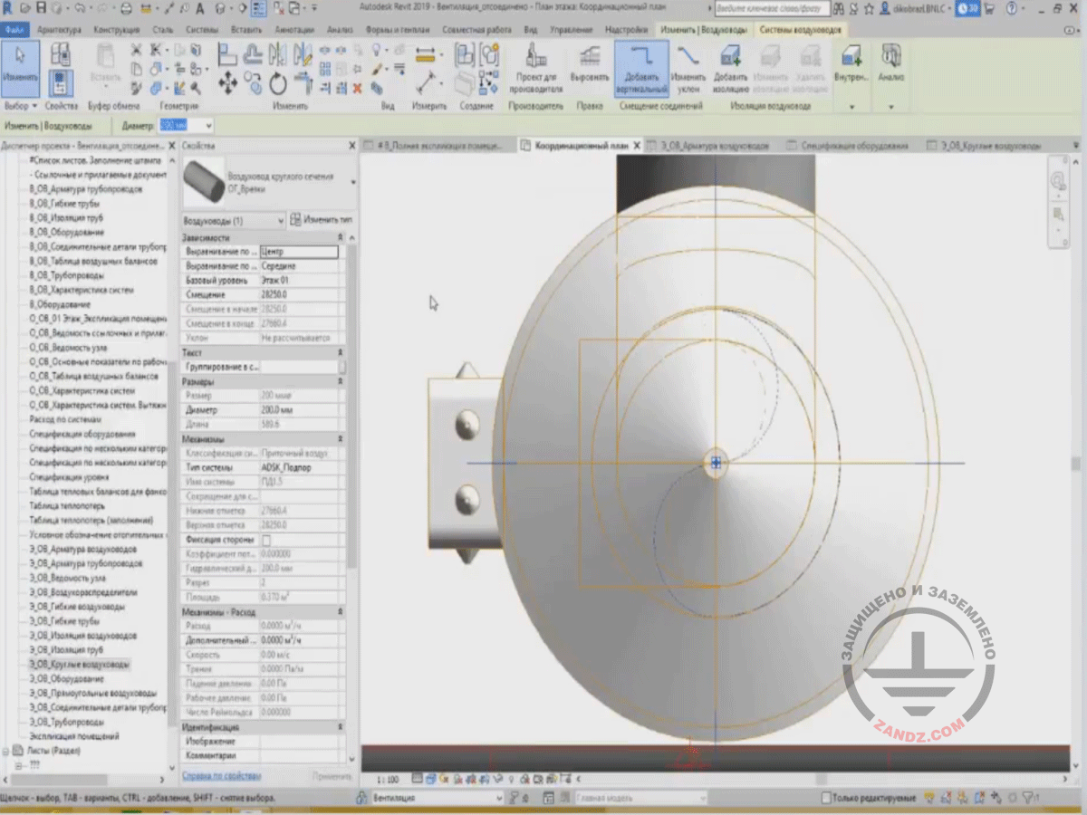
You can even see this if I highlight an air duct. This is a small one. I can see its length, which is 589 mm.
Demonstrating the air duct length
But in this case, this field has the length with a factor. Let's see what we have here. We have two lengths: one of them is actual, I have enabled it as it was hidden, i.e. 17.7 m, and respectively, the second length of 21.2 m, this is a length with a factor.
Hidden length and length with a factor
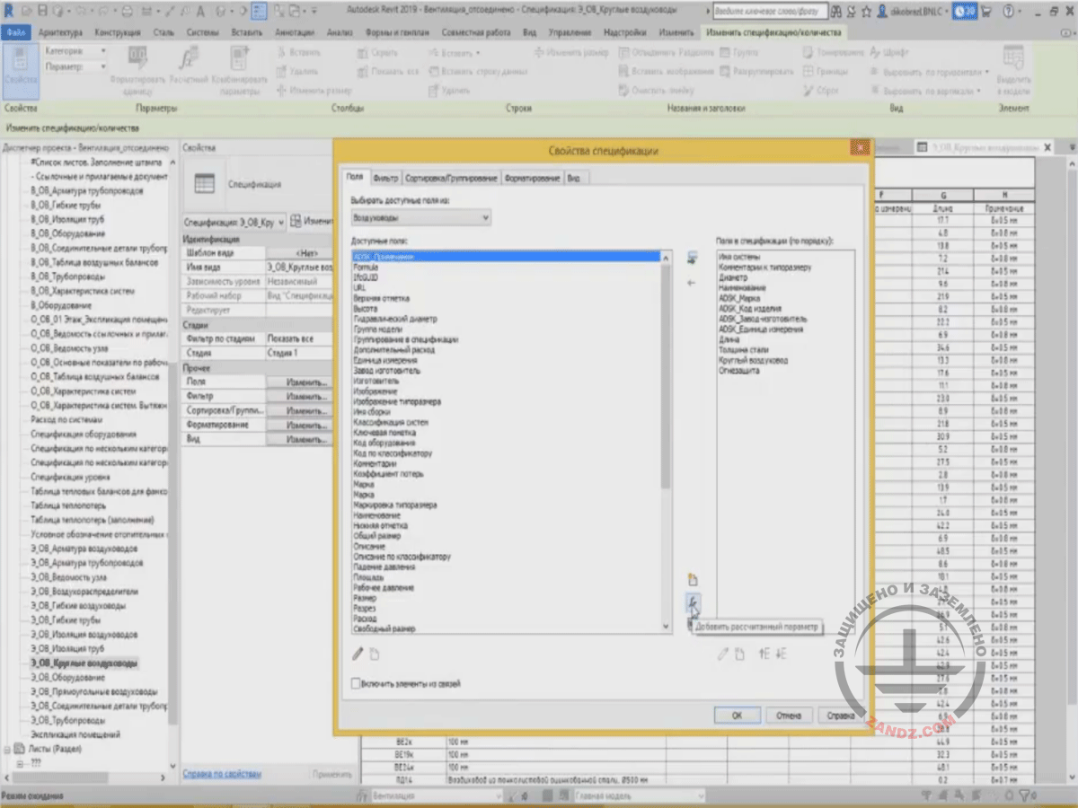
Let's delete it and create from scratch. We have the "Length" parameter that is the actual length, and for the project, we need a surplus. Therefore, we create the calculated value. In the “Field” tab, we press the "Calculated" button.
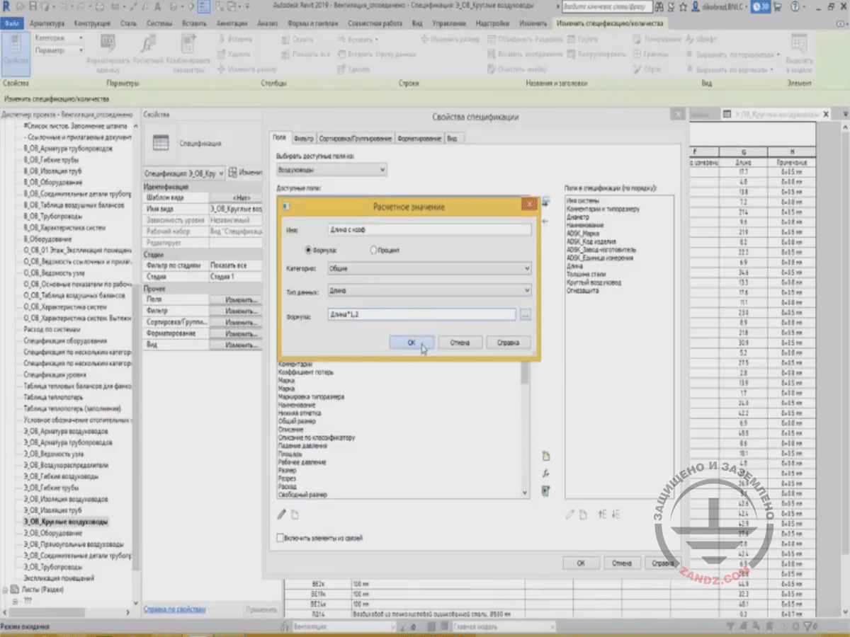
Creating new calculated value
A window appears where we enter the name "Length with a Factor". Then, we choose the data type. The data type is not a value but the length, so we will use this length. And then, the formula should include some parameters to obtain these calculated values. What parameters do we need? We need a length parameter. We can enter it using a keyboard. If a parameter's name is too long, then you can choose it from the list by pressing a square with three dots. And a list of fields that are added into the specification appears, and you can see that they are identical. Both here and there. So, we choose the length parameter and then choose the factor.
Length with a factor, increase
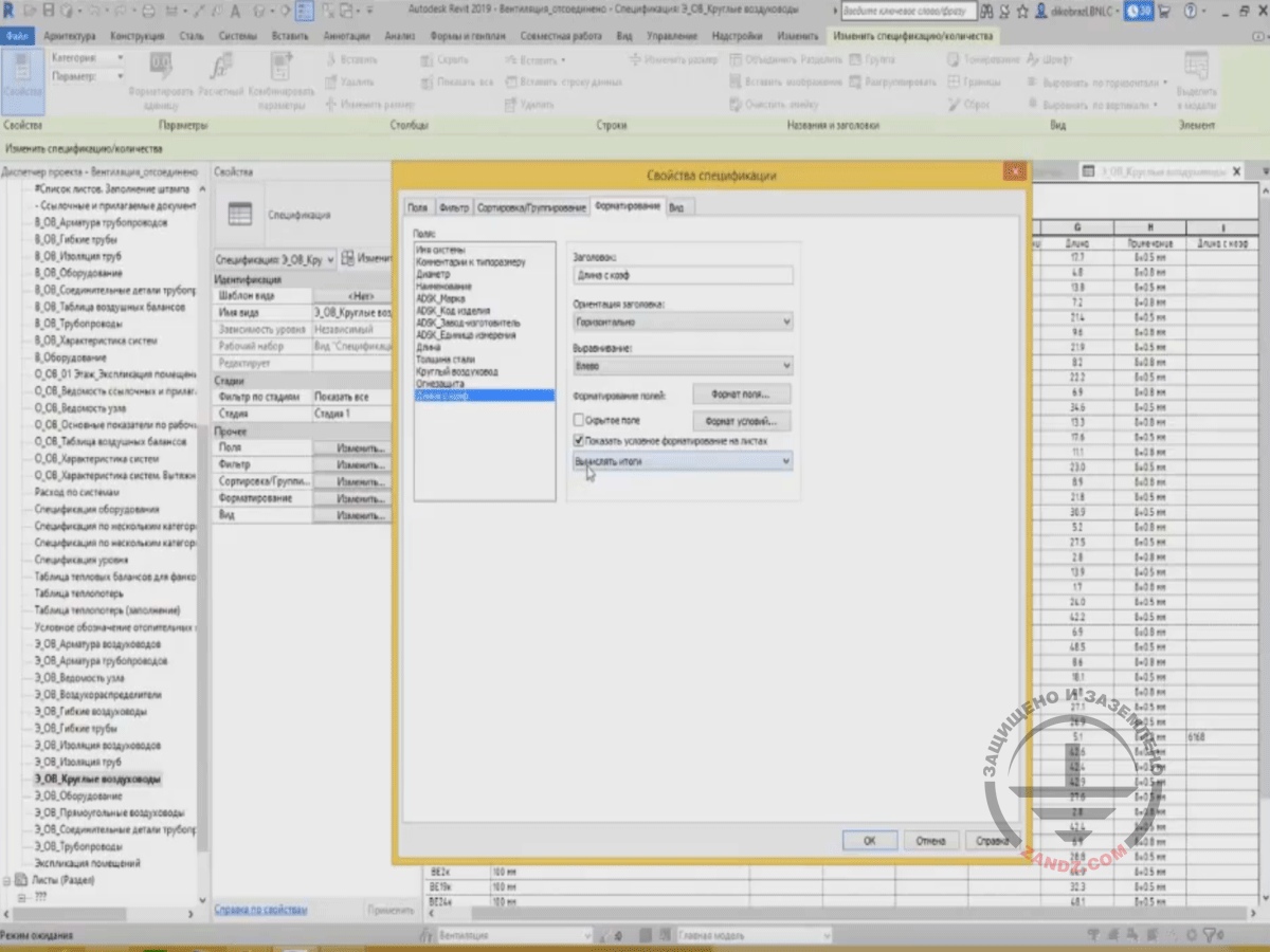
We have created the "Length with a Factor" parameter. This parameter is missing from the parameter list in the air duct category. It will be present only in the table. I will press OK and see this length parameter. But it can be seen that its values are not visible now. Why? To make its values visible, you should set the totals calculation in the "Formatting" tab. Here are several calculation options, but we choose "Calculate Totals". So, Revit will show us the sum for particular elements. Press OK.
Calculating totals
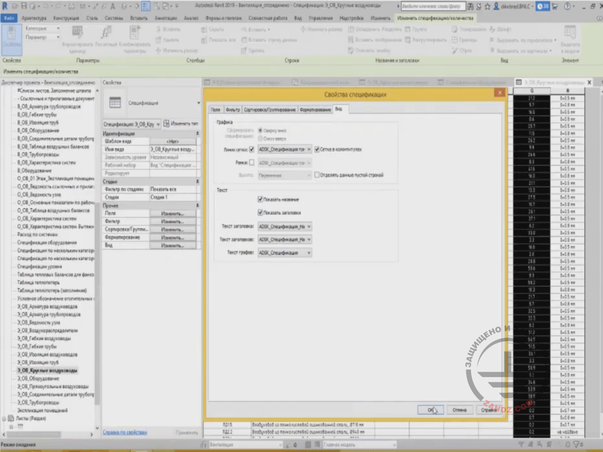
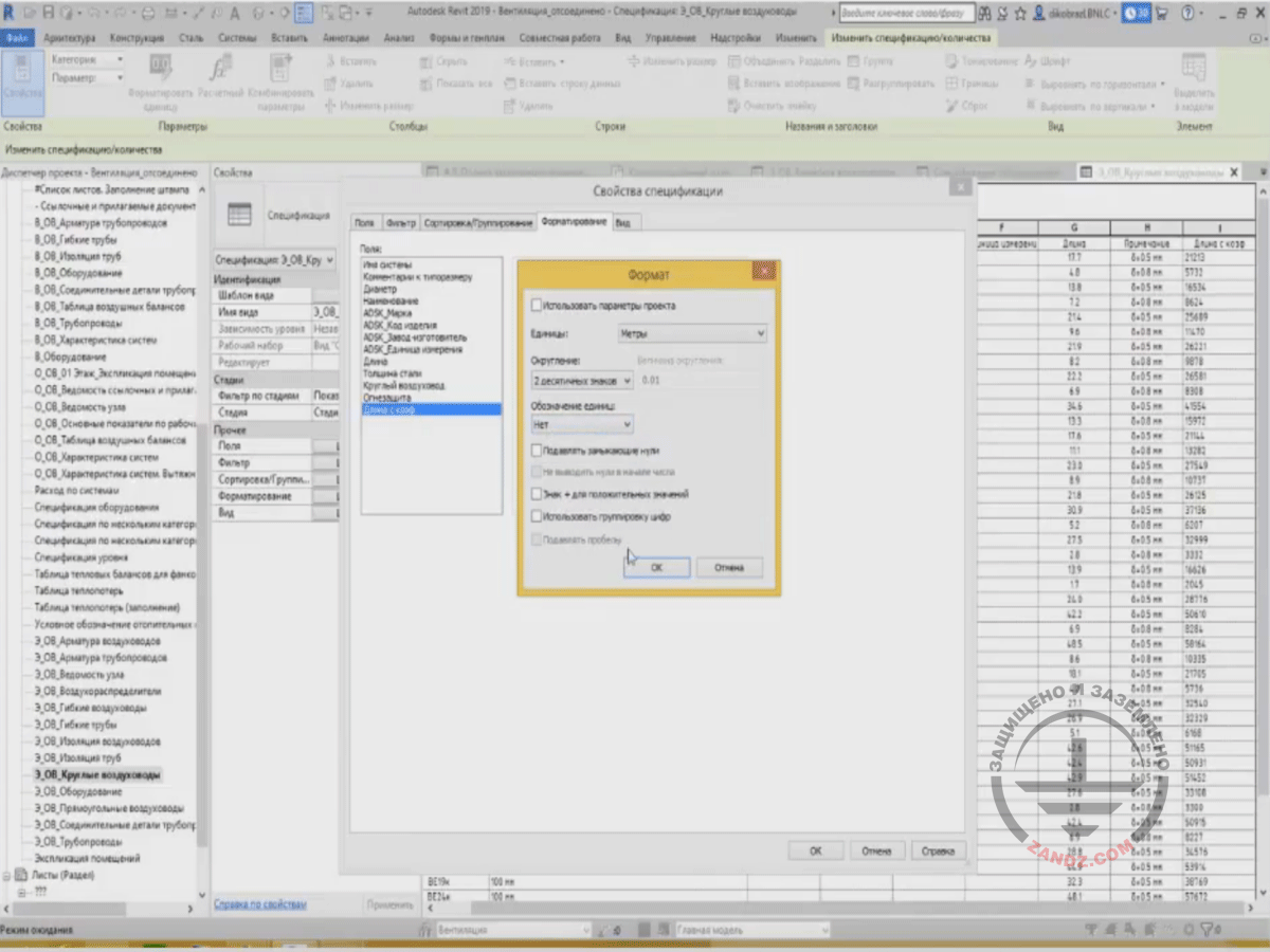
We have pressed “Calculate Totals”, and the length has appeared, although you can see that the length is not suitable, i.e. in millimeters, but we need it in meters. We need to display it in meters; therefore, we have to work some more, i.e. to change the data format. In the “Formatting” tab, let's choose our length with a factor and then choose “Field Format”. In the “Field Format”, we can choose the units of measurement, rounding, denotations for the units, etc. The “Use Project Parameters” parameter is ticked now. Since the project parameters display millimeters for the data type “Length”, then in this specification, millimeters are also used. But if you untick the parameter, you can determine the units of measurements you need for a certain specification, e.g., meters instead of millimeters. And we make rounding up to two signs after the decimal point. The denotations for the units, I suppose, are not needed, so we will turn them off and press OK. And then press OK again.
Changing data format
<< Previous page
slides from 1 to 16
Next page >>
slides from 33 to 48
Related Articles:
