The third webinar of the series "BIM Design: From Fundamentals to Practice"
Webinar text. Page 3
Fast navigation by slides:
Axis and level properties
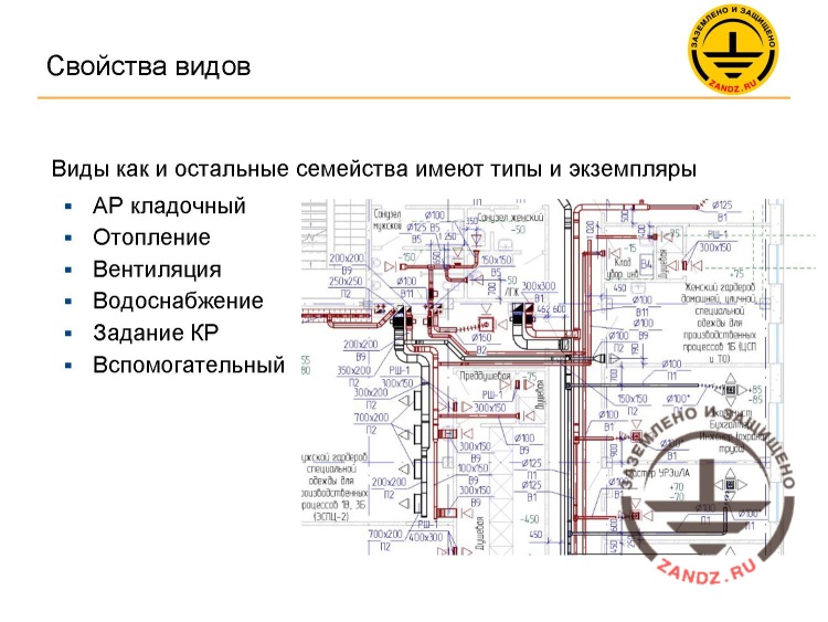
Свойства видов - View properties
Виды как и остальные семейства имеют типы и экземпляры - Views, just like other families, have their types and instances
АР кладочный - AP storey rod
Отопление - Heating
Вентиляция - Ventilation
Водоснабжение - Water supply
Задание КР - SP task
Вспомогательный - Auxiliary
– For you to understand, I will show you a small slide. The slide includes the axis and level properties. And each axis element, each axis instance consists of two families. This is a system family and a loadable family. Do you remember that the plane is a system family? In the previous webinar, I told you that the system family is always present in the project, and you cannot delete it, whereas the loadable family can be deleted completely, loaded from the external source, etc. And our system family is the line, i.e. the line in the projection, which is actually a plane. And the loadable family is this designation element. Why is it made like this? It is because axes are used anywhere; and in any company, in any country this element is the same. But designations may be different. For example, several sample axes are provided here. It is an axis having a diameter 8 mm, diameter 10 mm, it can be a double axis, if you need it for indicating dimensions, etc. We can change the designation. In any case, this element can be the axis family.
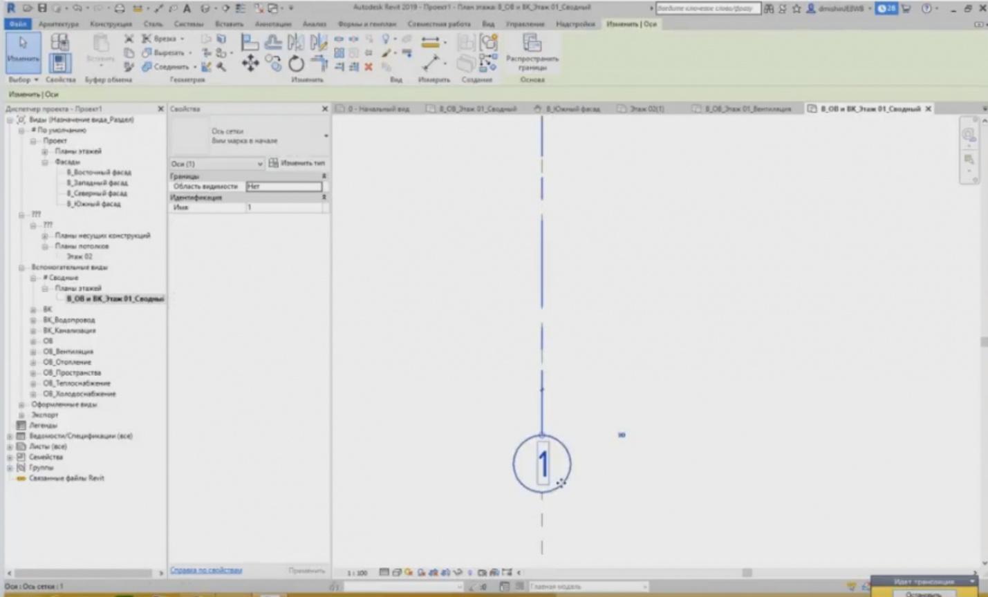
– Let's highlight the axis I have created. Here is our designation, and there is the axis. If we go to the type properties of the axis, they are available in the “Change Type” button. Press the button, and you can see some parameters of this axis type.
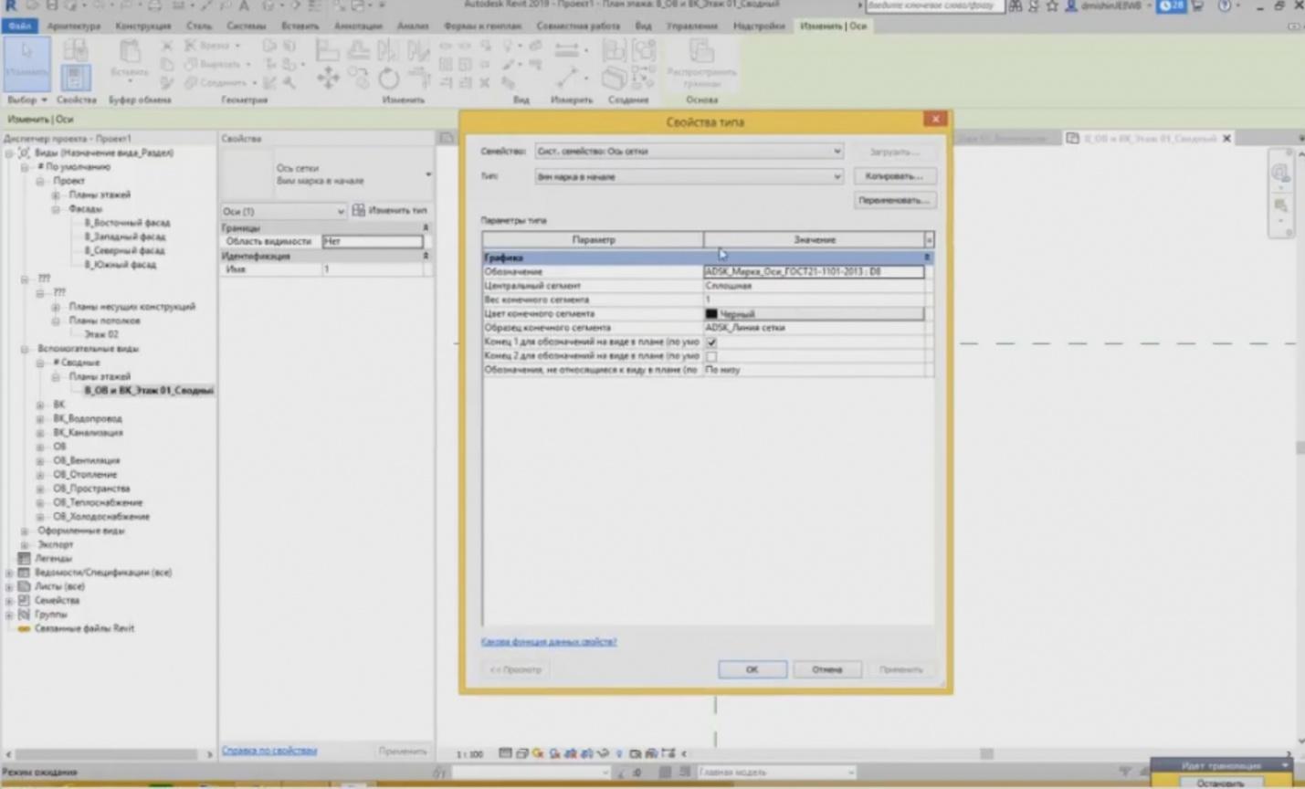
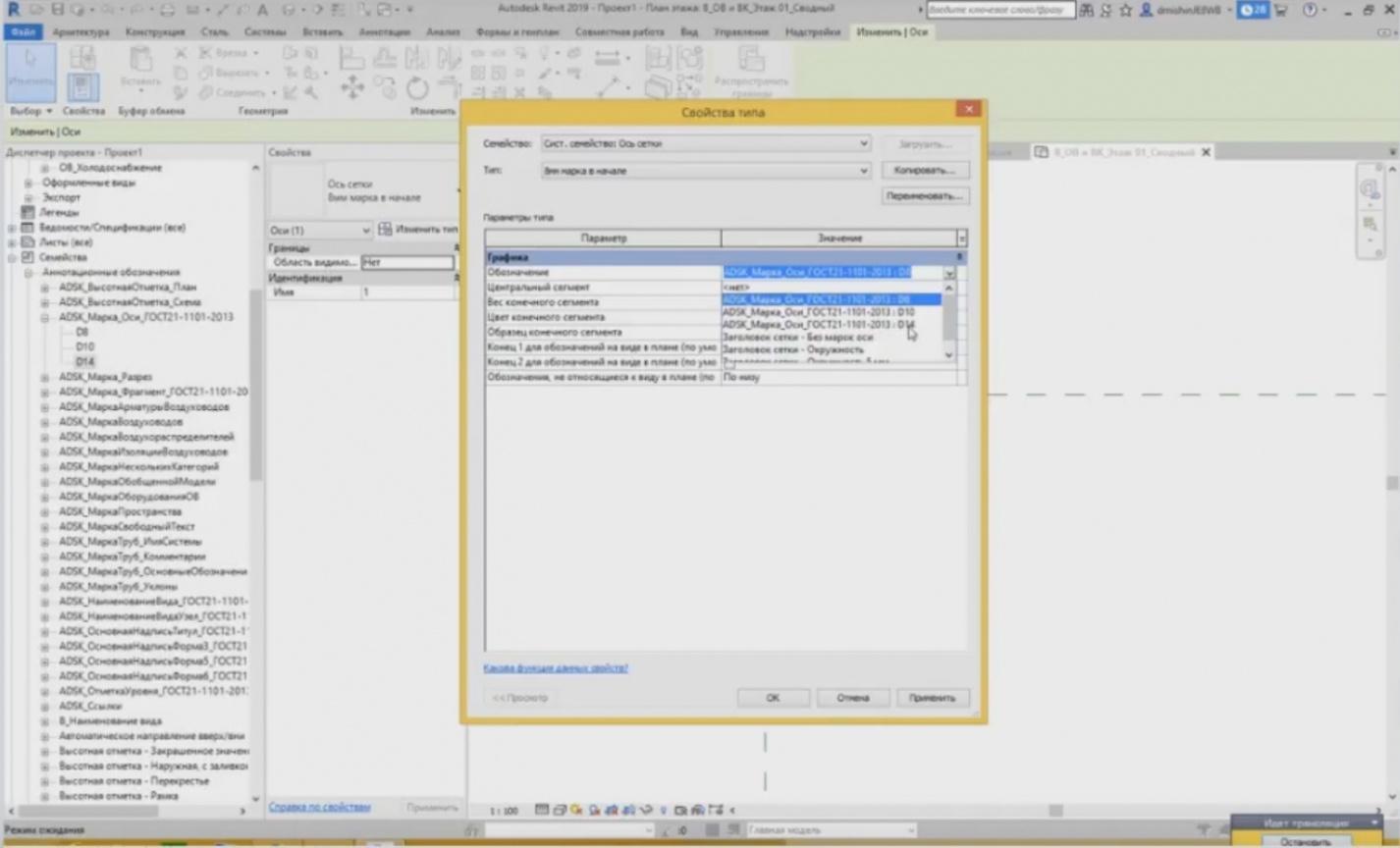
– On the top of the window, you can see what family it is. You can see that it is a “System Family: Grid Axis”. We can see the types of this family below. If we open the list, we will see that there are several types: three types of 8 mm and three types of 10 mm. 8 mm and 10 mm are the designations, i.e. the diameter of this circle. And we can choose designations in the parameters of this axis family. Designations belong to a loadable family. We can also open this list and we can see here that we can use the family with the diameter of 8 mm and the family with the diameter of 10 mm. And one more family titled “Grid Axis" for the 5 mm circle. If, with these settings, I press OK, then I will not see any difference but I can see in principle that the axis has changed. Its font and the circle diameter have changed. Now, where can we see the loadable families? Where are they? All loadable families we have ever loaded into the project, are in the “Project Browser”. Close the window.
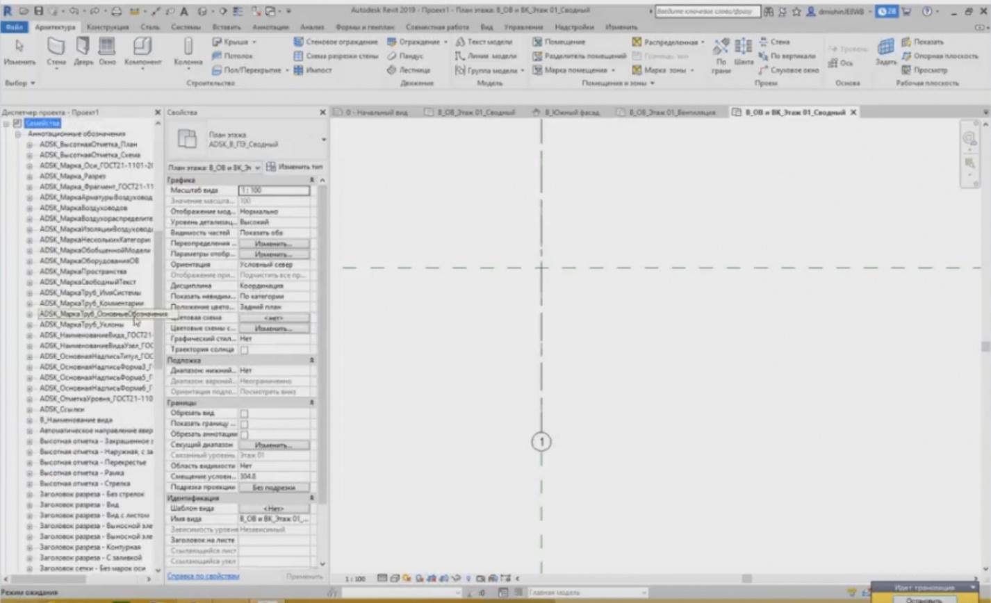
– In the “Project Browser”, we have a special “Families” tab. Open it and all families will be provided as a long list. Certainly, these are not only loadable but also system families; e.g., such as air ducts, curtain walls, flexible air ducts, roofs, staircases are loadable families. It is hard to find the loadable families here; these are mostly system families. Where can we find the representation of the axis? All representations of 2D elements are located in the annotation designations; therefore, we unfold the list and we can see in this tab a long list containing all annotation designations. Now, we are looking for the family of the axis designation. There it is: “ADSK_Axis Mark_GOST21”. Close the list; we have two types with the diameter 8 mm and the diameter 10 mm here.
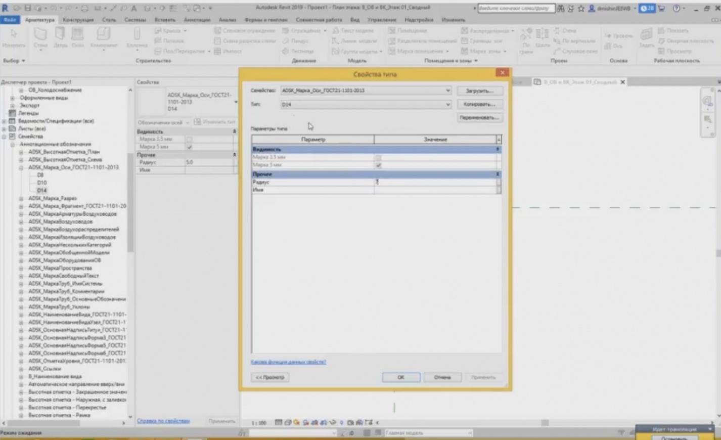
– We can create a new type, if necessary. Let's create 14 mm and set its radius at 7 mm. I have created a new type to designate the axis.
– Now, if I look in the properties of the system family of the axis, then it has already appeared in the list; here it is. I can choose it and see now that my axis has increased. It was like that, but now, it is like this.
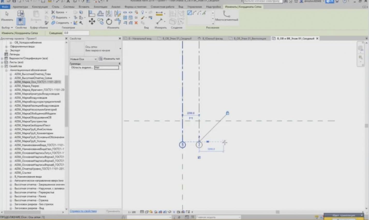
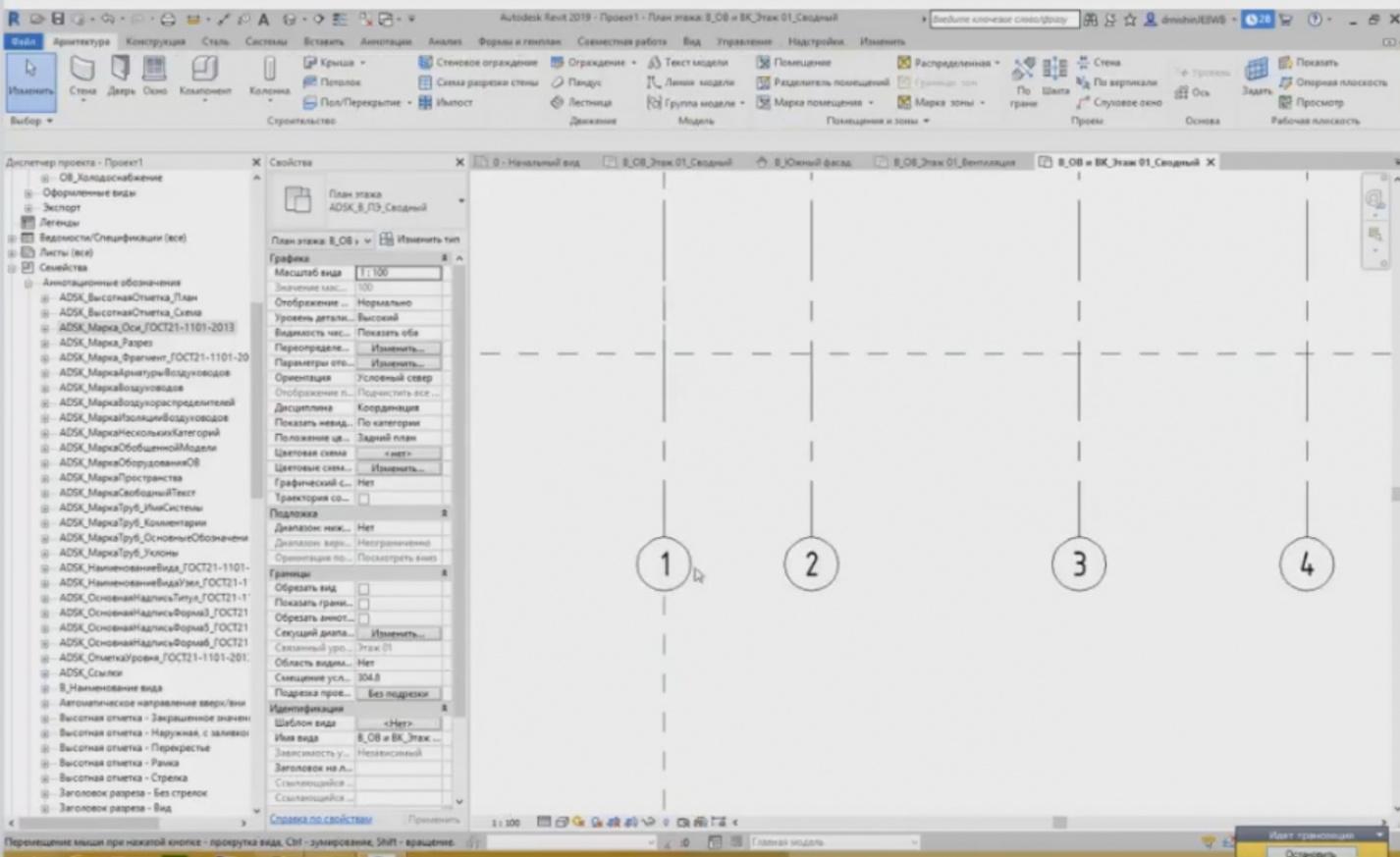
– Now, we are going to create a grid plan as an example. To create axes, we can use the “Axis” tool and create them one by one, choosing the required distance. A temporary dimension appears that is tied to the nearest element, e.g., we can see a value 3.7. If it is not convenient to look for the necessary value, you may enter it using the keyboard. For example, you may enter 4 meters instead of 3 meters. They are specified in millimeters. Press Enter and set the start and end points.
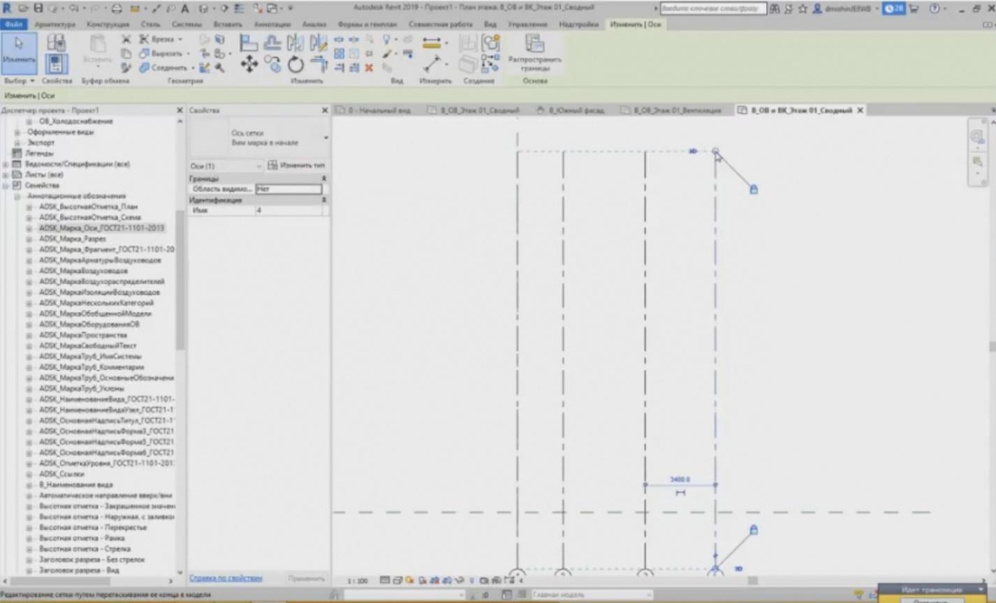
– In this case, the same principle is used as for the levels. If the plane boundaries coincide, then when you drag one axis, all of them are also dragged. It works in the following way both from the top and from the bottom.
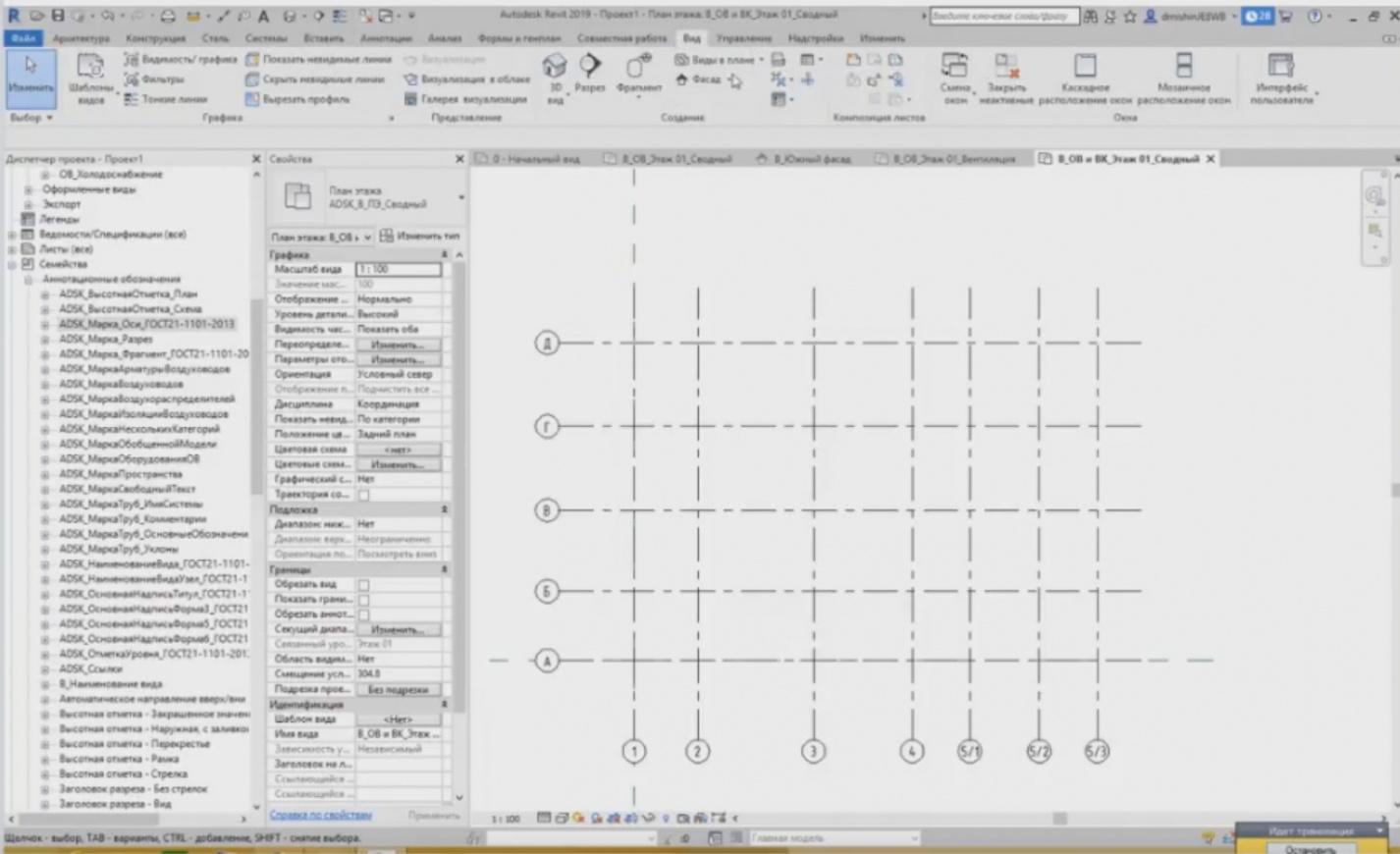
– Thus, the axes are always numbered sequentially. What can we do if the next, the fifth axis has literal designation? Naturally, Revit does not understand that you need to use literal designations for the axes, so we need to change it manually. Enter “A” instead of “6”, so the new axes will be created using literal designations. In addition to the creation of new axes, you can simply copy the existing ones.
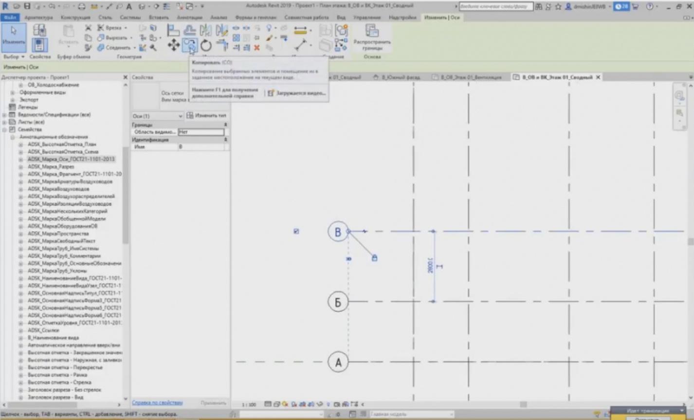
– If I highlight the axis and press the “Copy” button in the “Change” tab; here are the tools for changing the elements, their designations are the same as in AutoCAD. If you have seen new AutoCAD, the icons are the same. So, we copy them and in any case, the axis numbering will change. In addition to the simple values, we can also use the fractional values, etc.
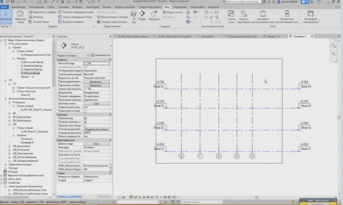
– And an important point will be mentioned now. Let's create cutaways. How is a cutaway created? The cutaway is created in the “View” tab or in the quick access panel. The quick access panel is located on the top of the window, where the “Open”, “Save”, “Print”, and other buttons are located. There is a “Cutaway” button. Some commands may be placed onto the quick access panel.
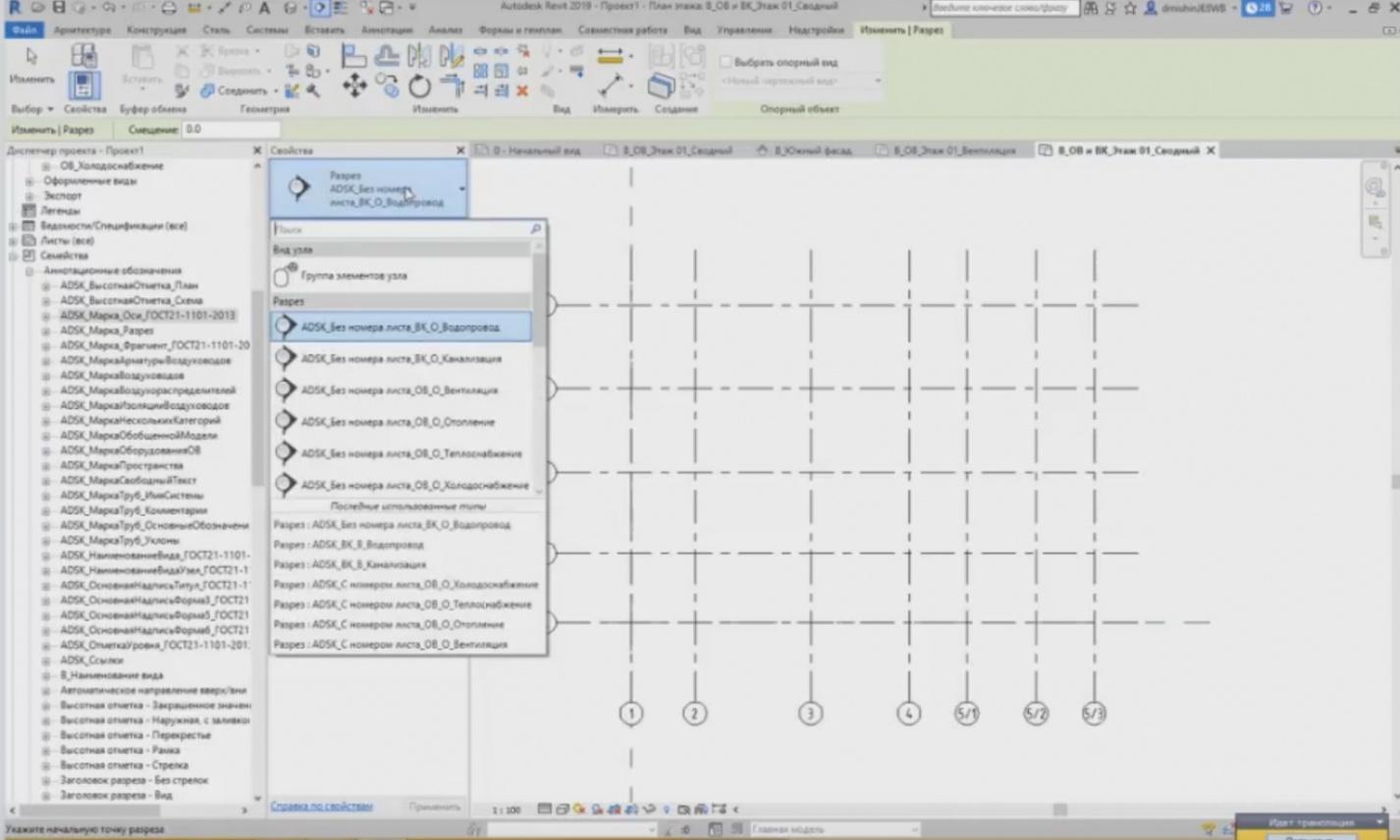
– Press the “Cutaway” button; we can also choose the cutaway type just like for the floor planes. The types are chosen in the properties window. Open it and you can see that we have many various cutaways intended for different tasks. For example, a cutaway for a water supply system, for sewage, for ventilation, for heating, etc. Since we have heating and ventilation section, let's choose, e.g., a HV cutaway. Just like for the axes, we set the start and end points.
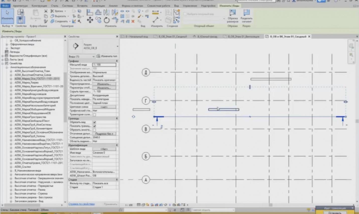
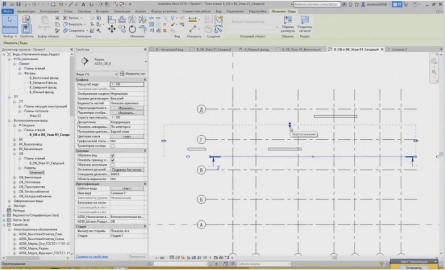
– We have set the start point, and we are indicating where the cutaway should end. You have drawn the end point, and we have this dotted line. What does it mean? The dotted line means the boundaries of our cutaway. So, everything that is beyond this rectangle, is not shown.

– For example, let's draw a wall here, another wall there, and one more this way. You can see that only this wall should appear in the cutaway view. To go to the cutaway view, I can use the “Project Browser” to find this cutaway. In our HV, the “Cutaways” — “Section 0” tab has appeared. Or a much easier way: highlight the cutaway by right-clicking “Go to View”.
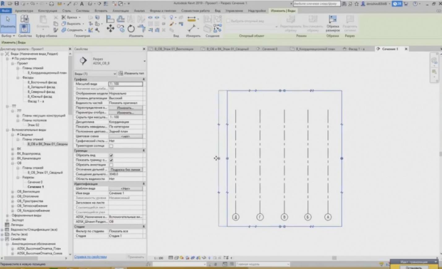
– What do we see here? We can see only one wall I have created, but we cannot see other walls. The cutaways have a clipping area; it can also be changed.
– When we change the clipping area, the cutaway representation also changes. What can we see there?
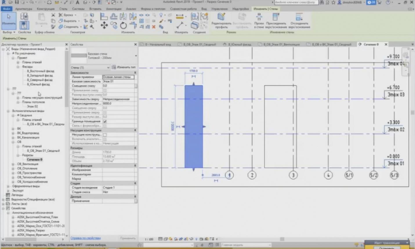
– Let's assume that if I pull it from the left, I will see the wall is drawn from the side.

– Now, if I highlight the cutaway, I will see that this rectangle has become more, and it is now showing this wall but not the other wall. How can I set the projection boundary? To what depth can the cutaway be seen?
– Now, the projection depth can be changed by dragging this element, these two arrows; it is the first option.
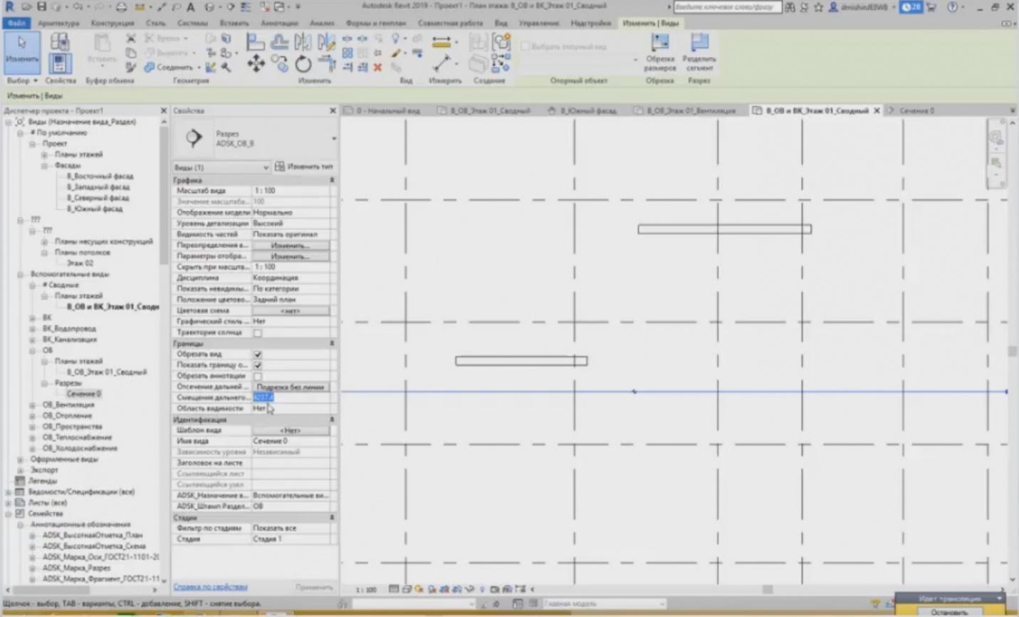
– Or the second option: in “Properties” of the cutaway, we have the “Cut by the Far Clip Plane” parameter. For example, we can set this value of 5 meters; you can see that it has increased.
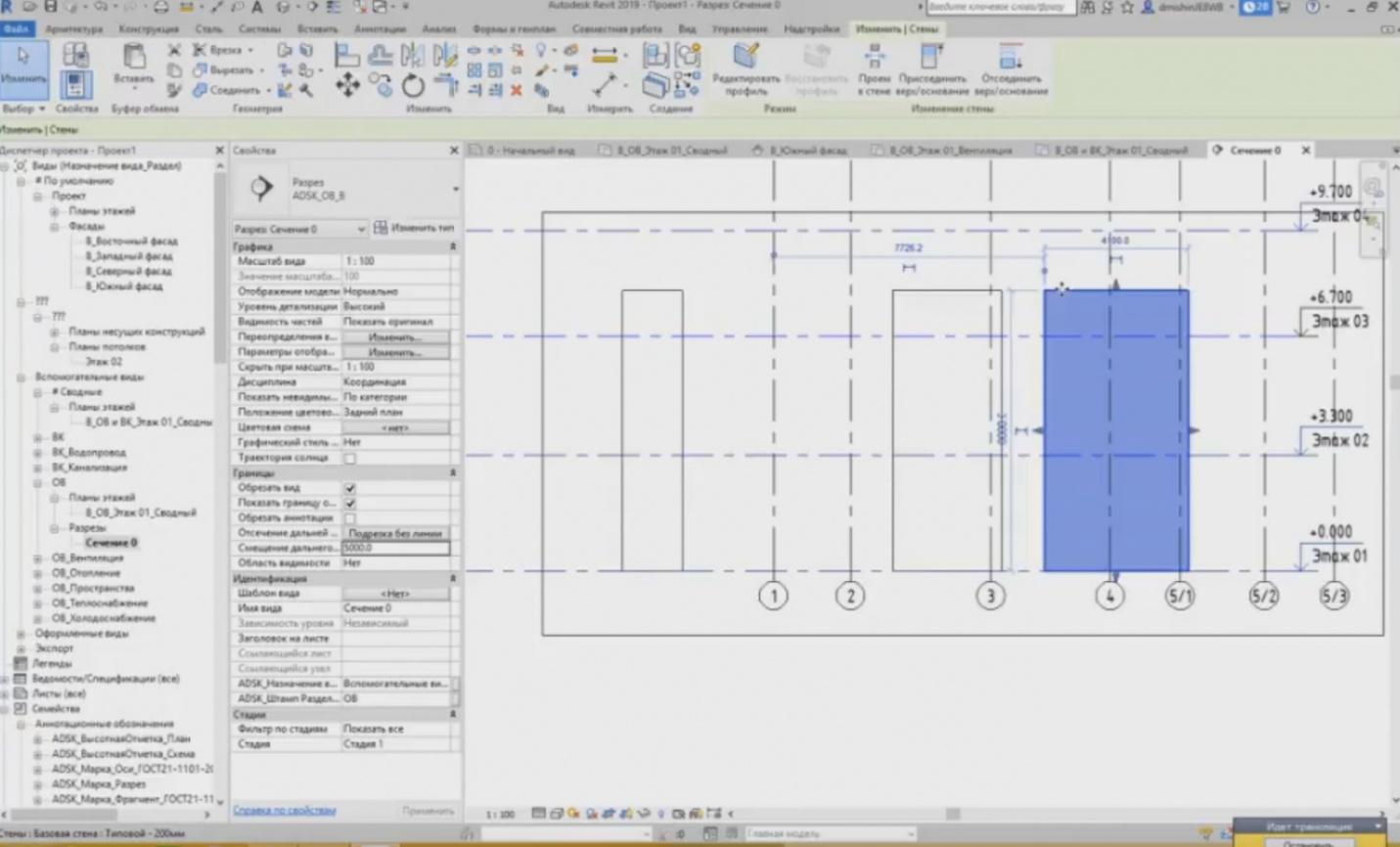
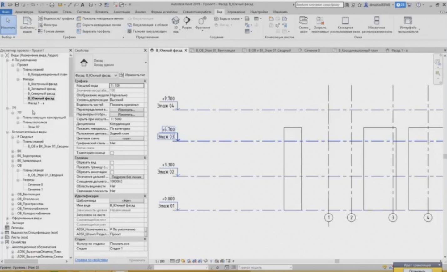
– So, if I go to this cutaway, I will see my last wall. The facade creation process is similar.
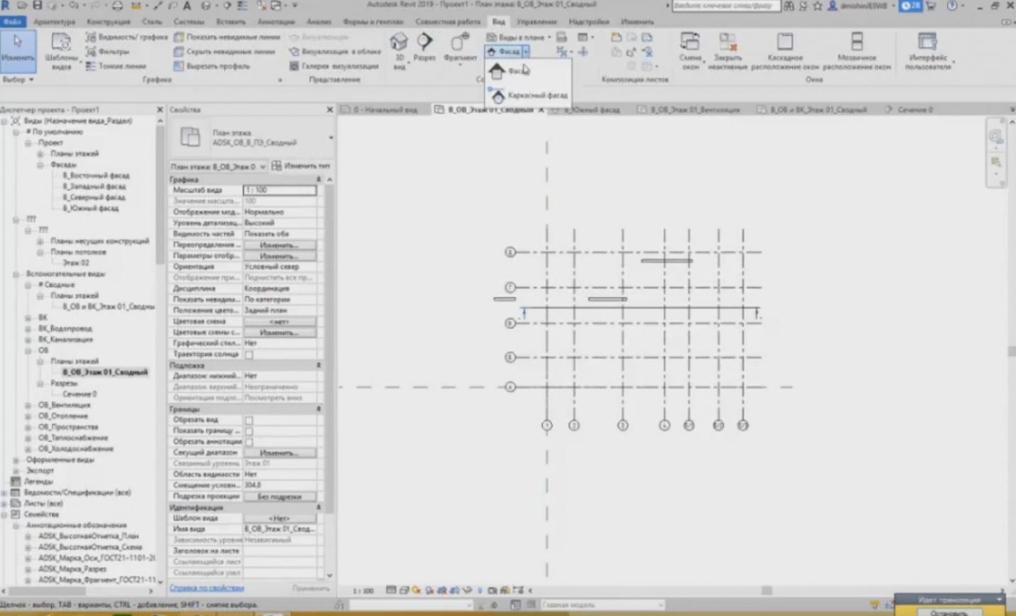
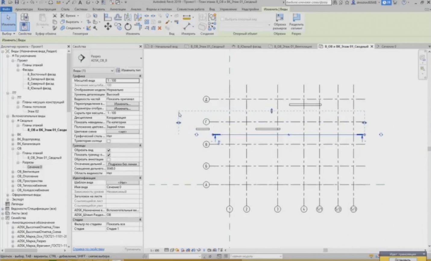
– Unfortunately, here (I will go to the coordination plan), the facades are created a little bit differently. We do not set the start and end points, we only determine from what side we will look at the element. It is tied to the elements.
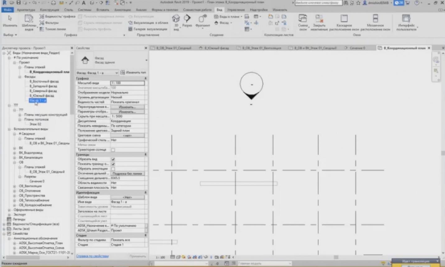
– It can “see” the edge of the wall and immediately changes its position. If I watch from this side, it will show to me from the right; if I watch from another side, it will it to me show me from the top. During the creation, our view, our facade appears.
– The facade does not differ much from the cutaway as the representation is similar. And here is an important information regarding why it is very important to understand that axes and levels are planes.
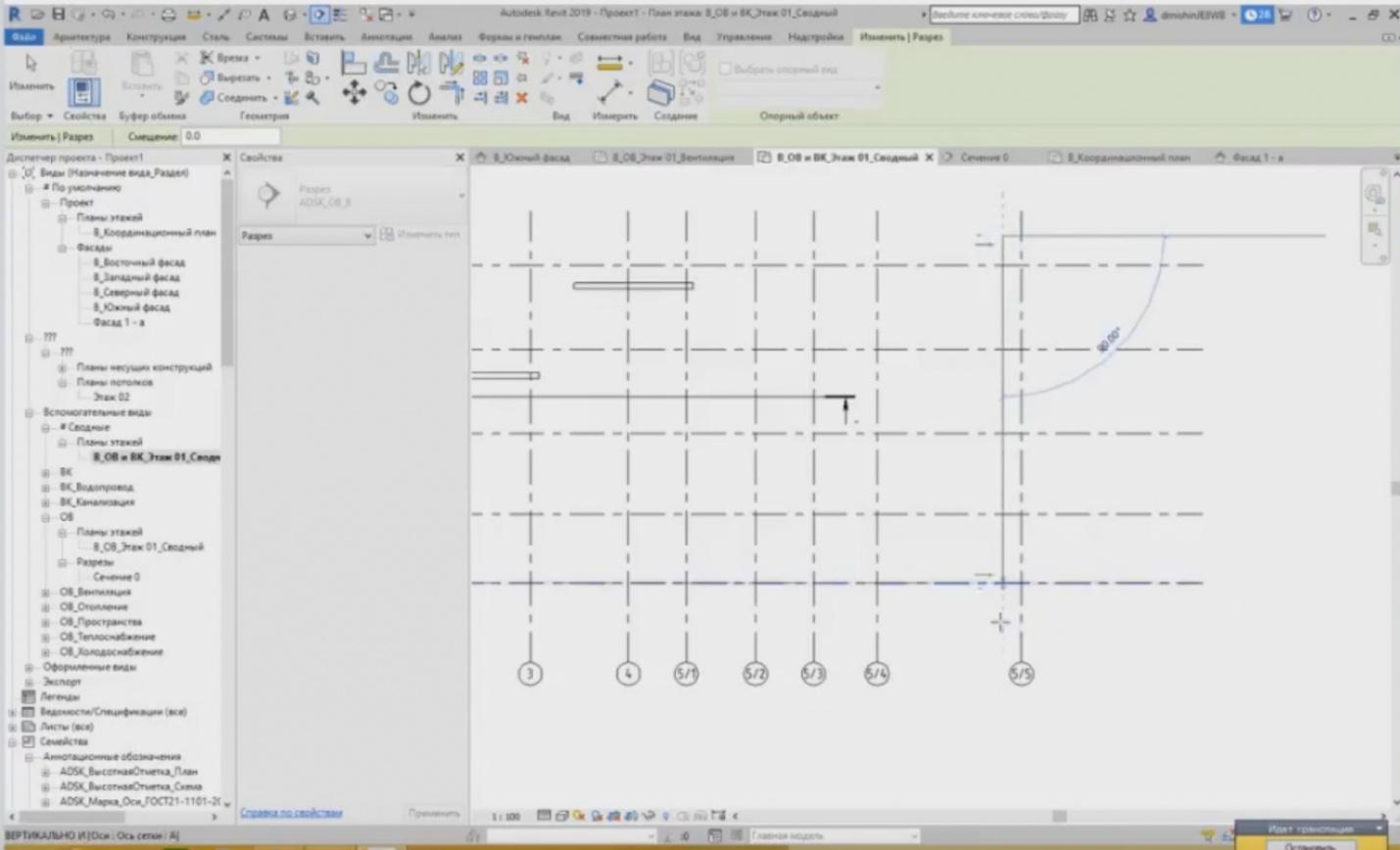
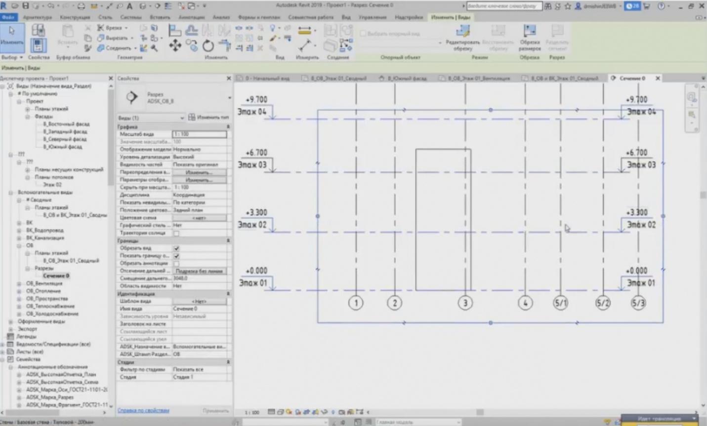
– I have created a cutaway and if I go to it, I can see that I have axes and levels. What happens if I create the cutaway this way? For example, I have many different axes here, and I create a cutaway in this location. Now, if I go to it, what will I see?
– I can see that the axes are shown here, while the levels are not. A very frequent problem is in that we cannot see the levels. How can we solve this problem and why does it take place?
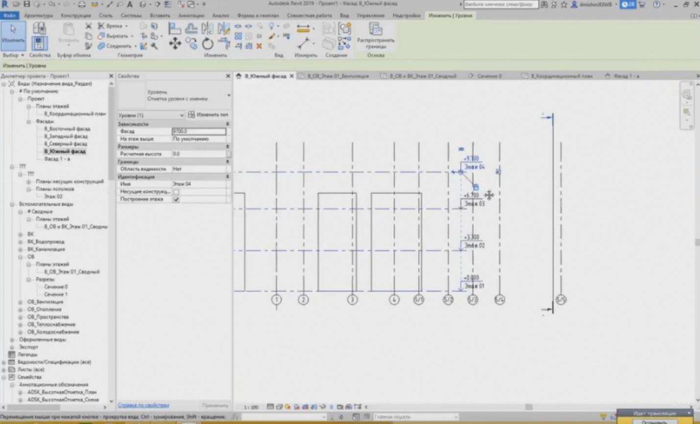
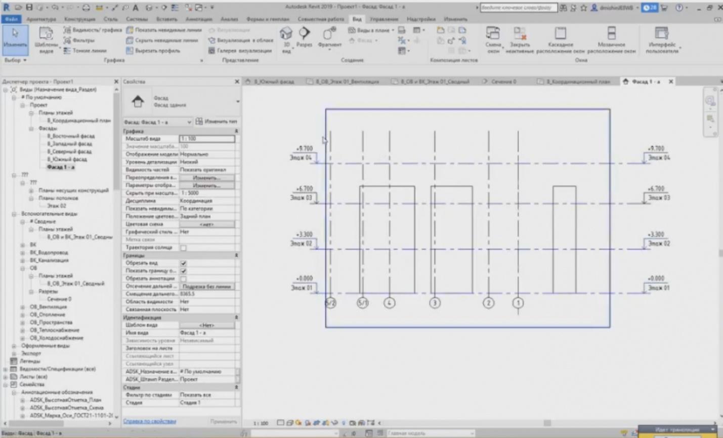
– If I go to the south facade, I will see that my clipping plane, the location where it goes, and this is where the levels go. As I can see, the levels do not reach the cutaway; so, in order to see the line of the level projection, I need to make these two planes intersecting.
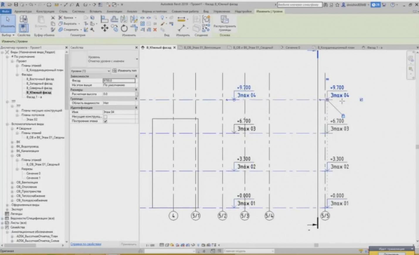
– Therefore, to see the levels, I pull the clipping planes to the intersection with the cutaway.
– Now, if I go to this view, the levels will be shown. This is how it works. It is important to understand that the levels and axes are planar elements. In order to see this element, we have to set the intersection of the two planes. And the intersection of the two planes is this projection line.
That's it. To summarize: the first point we have learnt today is that the levels and axes are the elements consisting of additional families, i.e. designation, the levels and axes family itself is a system family, but it also contains the designation family that is a loadable family. The second point is that the levels and axes are planar elements.
– For example, the level “Floor 01” is associated with this plan. That's all and thank you for watching. I am waiting for your questions. We already have questions.
– Stanislav, I would like to ask you to read the question before answering it, and then answer.
– “Where can I download the templates like yours?” The templates may be downloaded from the Autodesk website. It is much easier to use “Revit. Template” in any search engine and find the templates you need. For example, “Revit. HV template”, “Revit. AP template”, etc. You will obtain a link to the Autodesk website in the first results, and you can find this template there.
— The second question: “What can we do if we have one part of the floor in one level, while the other part is in another level, e.g., that is 1 meter higher?”
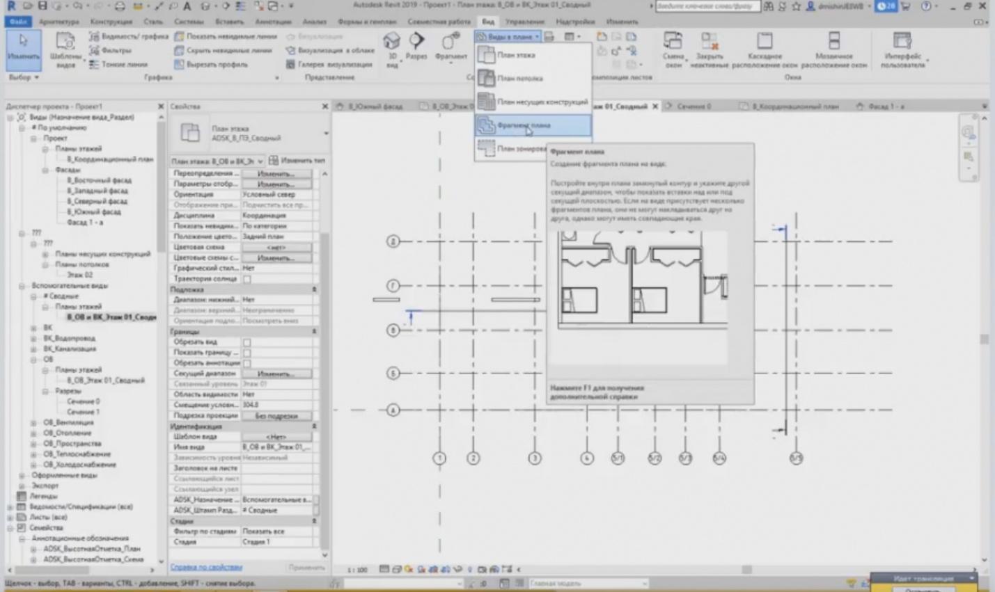
– Yes, it is a good question. In addition to the floor plan, and the floor plan has a particular clipping range, we can create a piece of a plan with another clipping range. Using the button, we can choose a region. For example, if, in this part of the building, e.g., not 0 but -1 meter, then in this part of the building, you create such contour and use the clipping range, e.g., -1 meter. And the elements at -1 meter relative to this level will be shown.
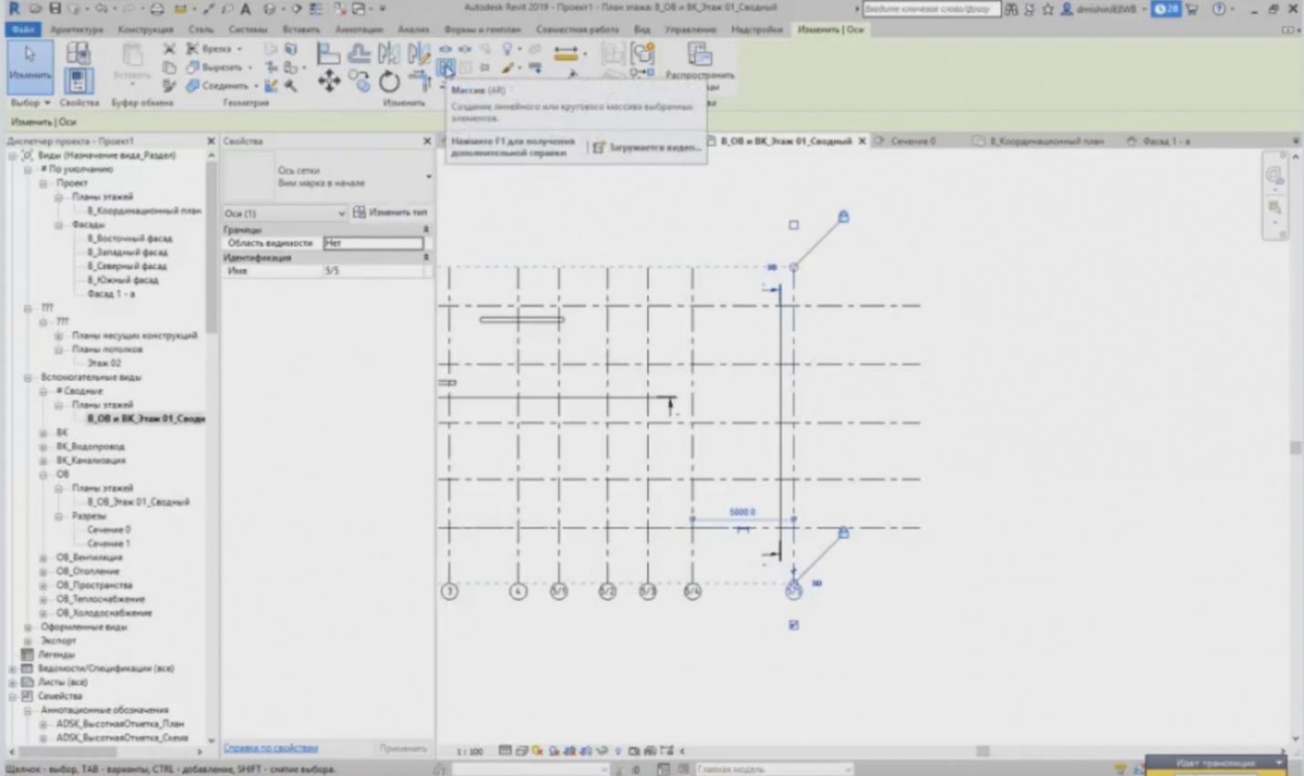
– Next question: “Can we create the axes automatically as an array by specifying the number of X and Y axes?”
– Yes, it is possible. When we highlight the existing axis, we use the “Array” button, and we can change it using this button.
– Dear colleagues, we have a pause. Write if you have questions. We have some time, 5–10 minutes, to answer them. If you have no questions, then write that there are no questions, and we will finish our broadcasting.
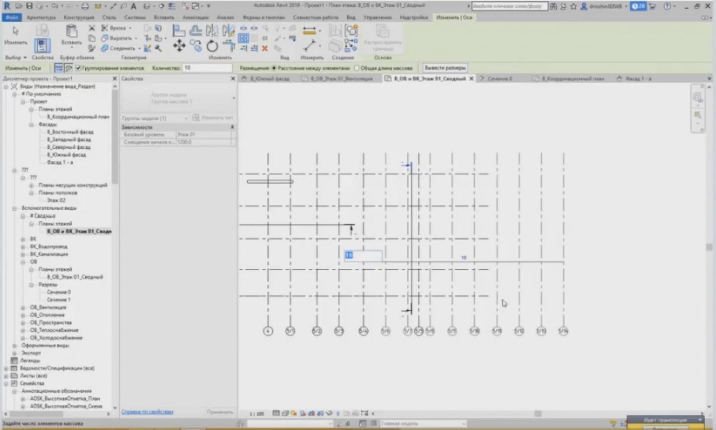
– There was a question: can we create an array? We have an “Array” tool and we can use it to create several axes at once. We choose the number and, e.g., create 10 pieces at once with a certain step, e.g., 2 meters. Several axes are created at once, so this is possible.
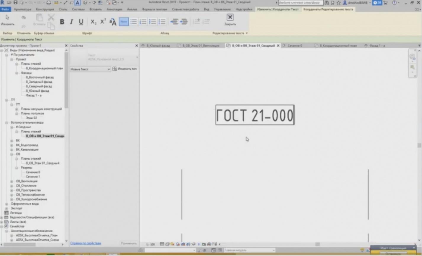
– The font is according to GOST. You can change it any way if you do not need it. GOST 21-000, etc. Here is what the font looks like. It is suitable for at least major part of users.
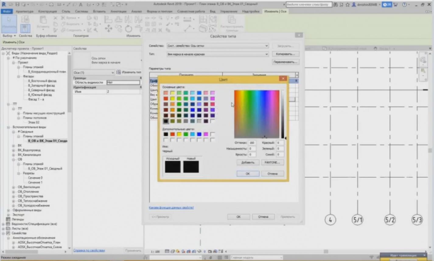
– It is also possible to change the axes colors. But, of course, you have to create new axis types for this. For example, we have a black axis. I can create a new type, copy the existing one and name it as “Red”, and then choose a color. It is red now. Since it is a loadable family, you can see that the element of the loadable family has not changed its color. Therefore, to change the color of the loadable element, you need to change it in the “Family Editor”, but it is a little bit more complicated.
– “What is our final aim?”
– Dear colleagues, I will clarify the final aim. The primary purpose of our webinars is to provide an input for the BIM technology and for the opportunity to employ it using Revit. This is the information we will provide and, surely, we will be glad if you will ultimately apply these tools to use our equipment in the lightning protection and earthing projects. But the webinars are aimed at providing the information, i.e. giving you the tool.
– “How can we provide comments and general instructions?”
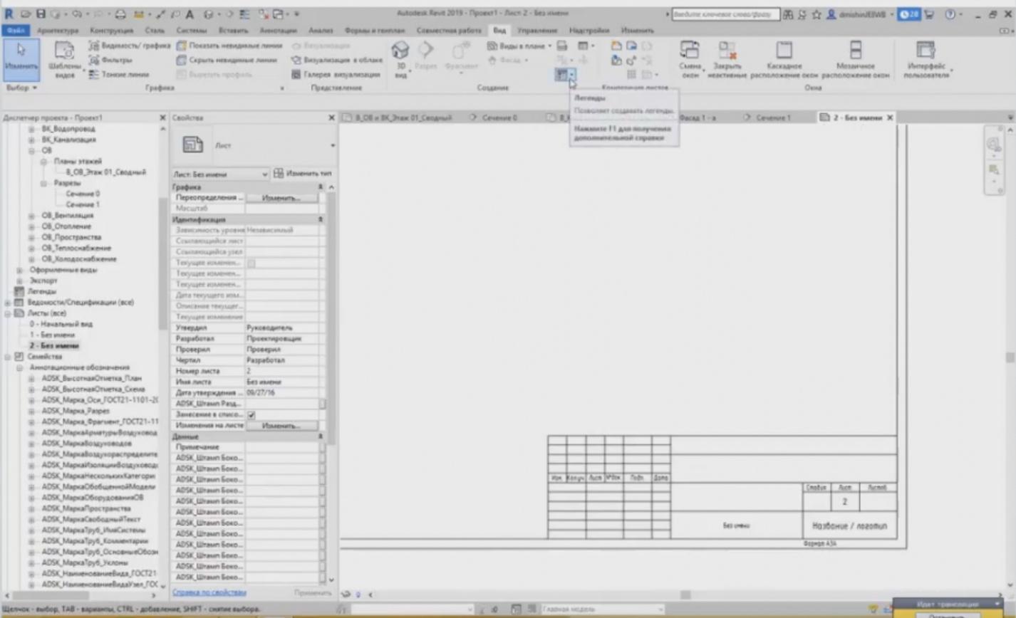
– Comments can be added using text comments, e.g. on the sheet. Here, a certain sheet has already been provided. You may add comments and enter the first, the second points, etc. You can create them this way or you can use the “Legend” tool. With this tool, we can create such comments, symbols that can be later added on the sheets, or follow the second option: using the text immediately on the sheet, we can enter any information this way.
– Dear colleagues, we can see that there are no more questions. Thank you very much, Stanislav. Dear participants, thank you for your participation. Register for the next webinas. Let me remind you that the next webinar of this series will be held on June 20. Join us and take part. I will send you the link to the webinar series in the chat again. We have finished.
– Thank you for watching. Bye!
<< Previous page
slides from 3 to 4
Next webinar >>
Related Articles:
 Webinar «Software structure and general concepts of revit», page 2
 Webinar «Software structure and general concepts of revit», page 3
 Webinar «BIM design in Revit. Getting started», page 1
 Webinar «BIM design in Revit. Getting started», page 2