The third webinar of the series "BIM Design: From Fundamentals to Practice"
(held on May 24, 2018 at 11:00 Moscow time)
The webinar plan:
- getting to know the user interface;
- creating a grid plan;
- creating levels;
- creating views (cutaways, facades, and floor plans).
720p full screen watching is recommended.
Webinar text. Page 1
Fast navigation by slides:
Approximate reading time: 39 minutes.

BIM Design in Revit. Getting started
В1М проектирование в Revit. Первые этапы работы - BIM Design in Revit. Getting started
ZANDZ.com, май 2018 - ZANDZ.com, May 2018
– Good afternoon, dear colleagues!
– Good afternoon, Stanislav!
– Good afternoon for everyone.
– Let's begin! We are starting our current webinar dedicated to: “BIM Design in Revit. Getting Started”. The speaker is Stanislav Vozchikov, the BIM modelling specialist and the certified Autodesk Revit Professional specialist. Today, it is our third webinar of the series titled: “BIM Design: From Fundamentals to Practice”. I am glad to greet you again! I hope our webinars are really useful, that is why you take part in them. Let me remind you that our next webinar will be held on June 20. I have sent the link to register for the webinar series in the chat. Please register so that not to miss further events. You can get information about our new events on the website and also in our social media groups. Join the social media groups or register at the website. Do not miss the relevant events. Here are some organizational aspects: our webinar will take 60 minutes.
– Yes, thank you. OK, let's start! We have the subject titled “Getting Started” today. What are we going to study? We will study the process of creating a project using a template, creating different views, floor plans, facades, cutaways, 3D views, etc. We will study the creation of levels and grid plans. Before we create anything, we first need to choose the template based on which we will create the entire project. Therefore, today we will have a practical webinar. I will show you the actions in Revit, but some slides will also be shown in the presentation.
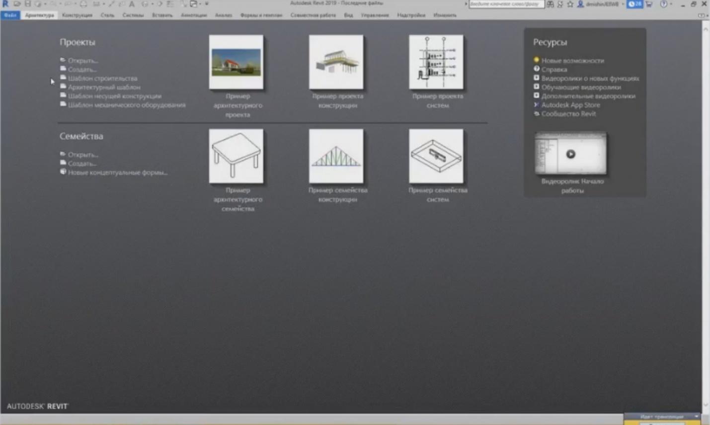
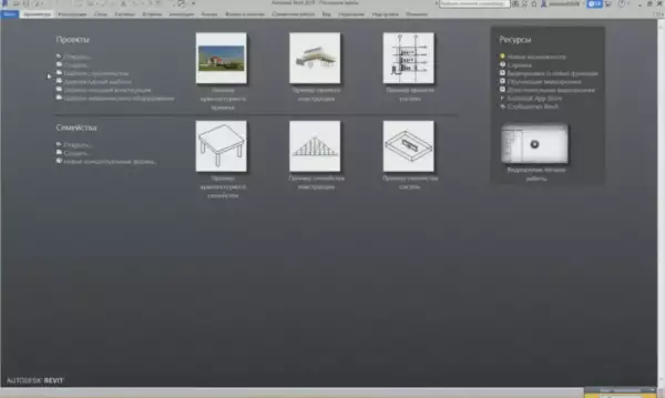
– Let's launch Revit. Today, we will use Revit 19, i.e. the latest version. First, we have to create the file. The files are created in Revit using templates. I hope that the participants remember this from the previous webinar. The templates are stored in Revit. The standard templates are four templates that are always installed, including the construction template, the architectural template, the bearing structure template, and the mechanical equipment template. In general, they are not really needed. Why? Because they are not actually used in Russia. We have the Russian Autodesk Community that has developed the templates for Russia. I have already told about it in the previous webinar. Generally, we can use them for training purpose. First, in order to create a project, we have to load these templates. To do this, press the “Files” button and then “New Project”.
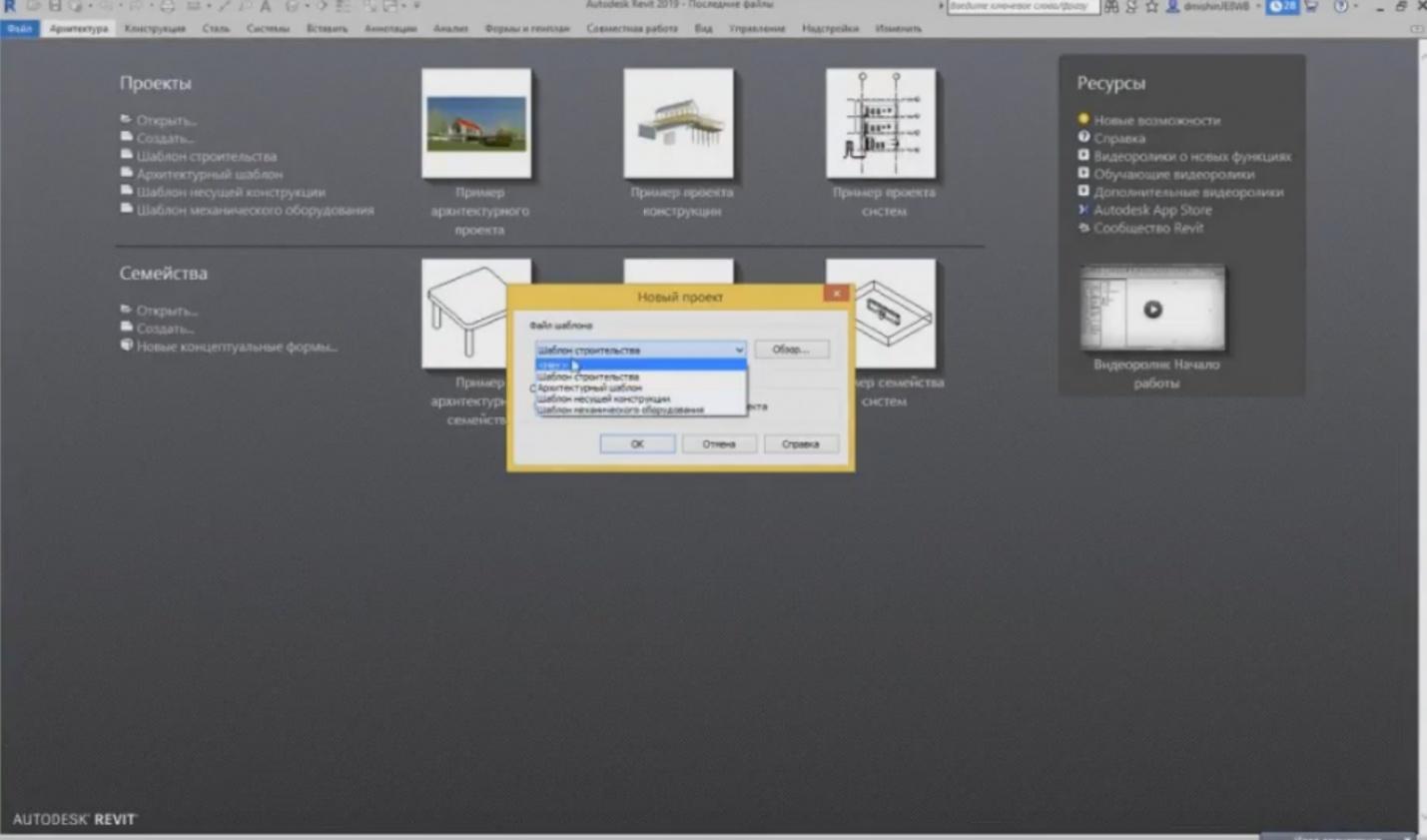
– When we press the “New Project” button, we can see a list of templates that have been loaded, i.e. four basic templates. We can find the template we need using the “Browse” button. For example, if you have downloaded it from Internet, or another template is stored in a folder. But it is inconvenient to do that each time; therefore, it is easier to load these templates initially so that they would always be present in this template list.
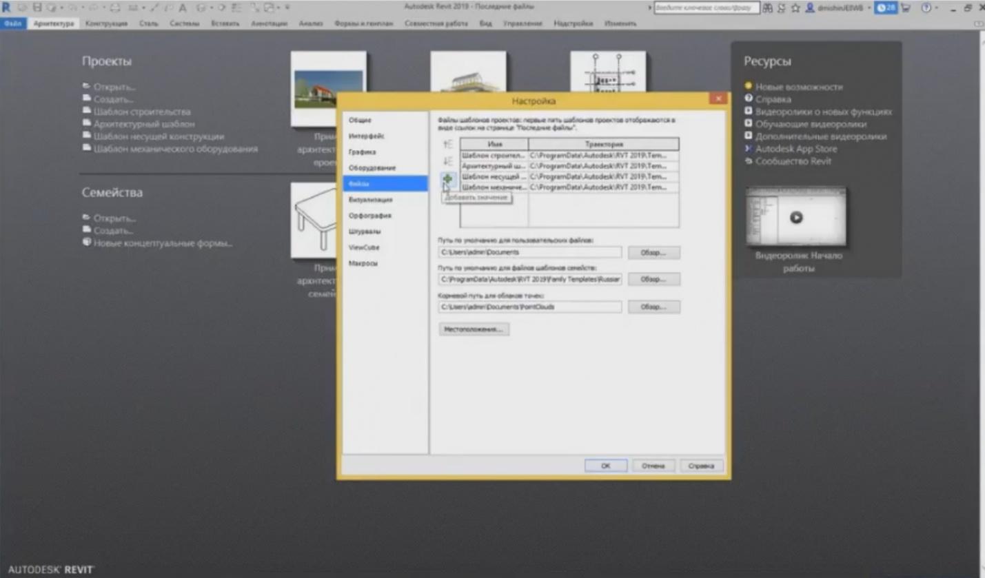
– To do this, go to the “Files” tab and press the “Parameters” button. We have four templates in the “Files” tab. To add a path to a template, use the “+” button. The templates may be deleted or moved, if necessary. They are not really needed, so you can delete them. Press “+”. I have prepared two templates. These are the ones taken from the Russian Autodesk Community, these are HVAC templates and an AP template. Let's load both. So, they have appeared here. Press “OK”.
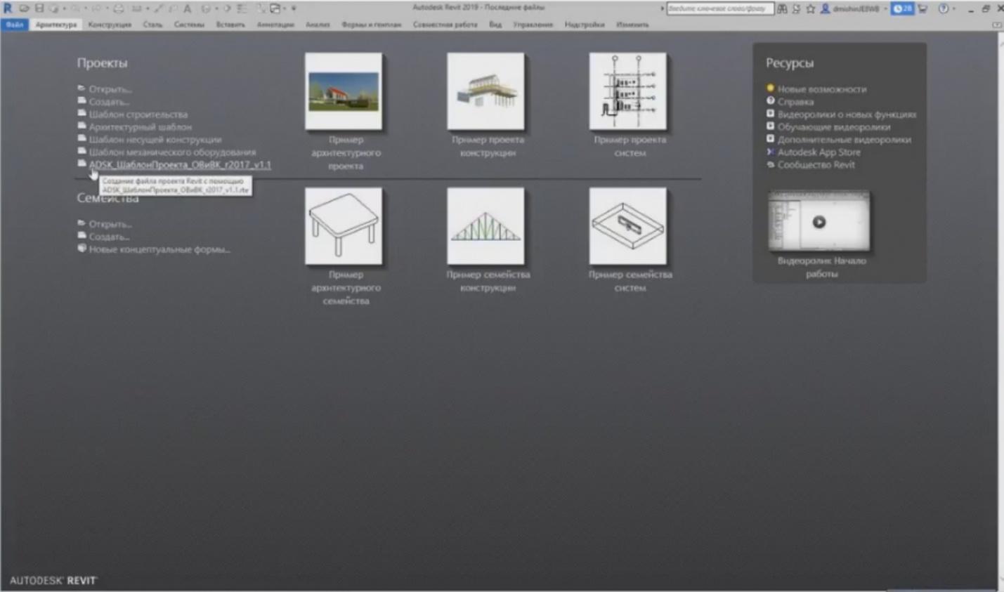
– After loading, they appear in the quick access toolbar. I can create the project using this template. Either press “Create” and select from the list or just click on the template.
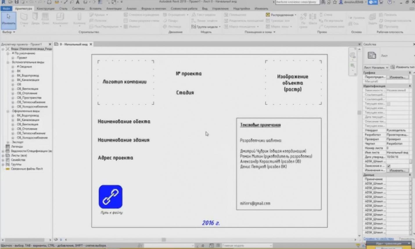
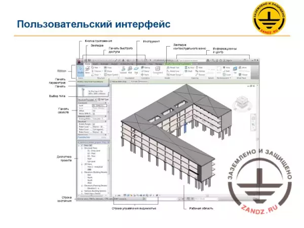
– An initial screen opens. We have already launched Revit. As I told you in the previous webinar, we have two main windows: “Project Browser” and “Properties”. “Properties” are on the right now, while “Project Browser” is on the left. These windows can be dragged and dropped anywhere, they can be combined, if your screen is small, or you may replace them in any convenient way. But I consider this view to be most convenient when we have the necessary tools on one side of the window and a working area on the right. Let's see now what we have here. “Project Browser” is configured so that, in the HVAC template, we have “Auxiliary Views” and the so-called “Stylized Views”. The “Auxiliary Views” are necessary to create a model, draw using any lines for details, show some elements, which we do not need in the “Stylized Views”; i.e. do almost anything. The “Stylized Views” are configured so that the excessive elements would not be seen there and they are intended to place them on the sheets. This is a hierarchy.
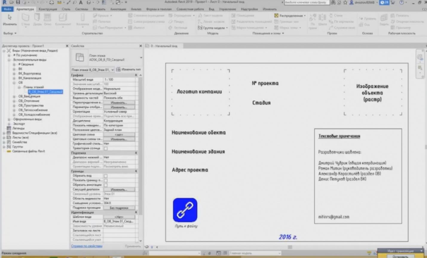
– Let's go to the “Auxiliary Views” tab now. We have the “VC” and “HV” sections. Let's choose “HV” as an example. We have floor plans here. The abbreviated name "A_HV_Floor01_Combined" contains meaningful elements. “A” means the auxiliary view, “HV” means that it relates to heating and ventilation, “Floor01” means that it relates to the floor 01 level, and “Combined” means that it is a combined view showing heating, ventilation, heat supply, water supply, etc.
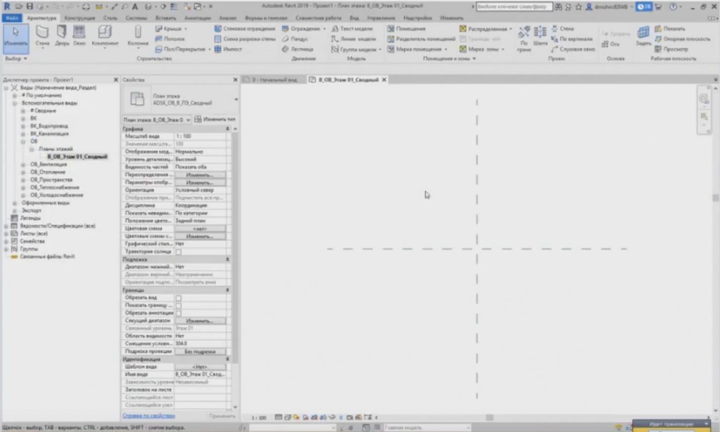
– Go to this view. Since our model is empty, i.e. we do not see anything, we have only two reference planes here. What are they? The intersection of these reference planes means the project starting point. These are coordinates (0;0). The reference planes cannot be seen in other templates. The reference planes are drawn here intentionally to see this point. Each time you start a project, it is recommended to start it with the intersection of the reference planes and align it with the intersection of axes starting point 1A so that the project would start from a single point each time. It is very important for further collaboration.
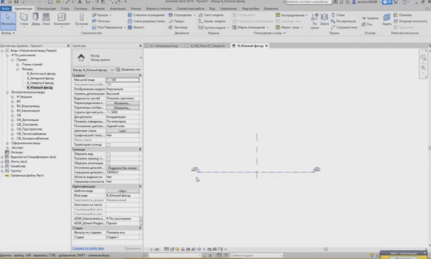
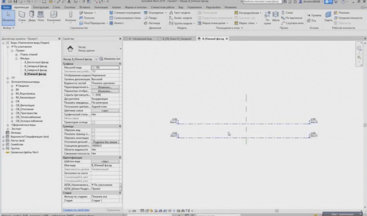
– Go to the default views. We have “Facades” here. Let's look at what the “Facades” show. They have a so-called level. It has a mark and a level name.
Axes and levels
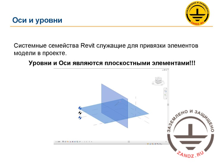
Оси и уровни - Axes and levels
Системные семейства Revit служащие для привязки элементов модели в проекте - The Revit system families that serve to tie the model elements in the project
Уровни и Оси являются плоскостными элементами!!! - Levels and Axes are planar elements!!!
– First, we will create the grid plan. We will study how to create it and what it is, and then create levels. In the first hand, I will show you how to create levels. I will show a very important aspect in the presentation. What are levels and axes? We got used to that, in AutoCAD, these are simple lines on a plan or a cutaway view, but Revit contains planar objects rather than linear ones. If you look at it, then you will see the axis as a projection, but in 3D views, this line is not a line but a plane, the projection of which is a typical line. You can imagine two such planes here.
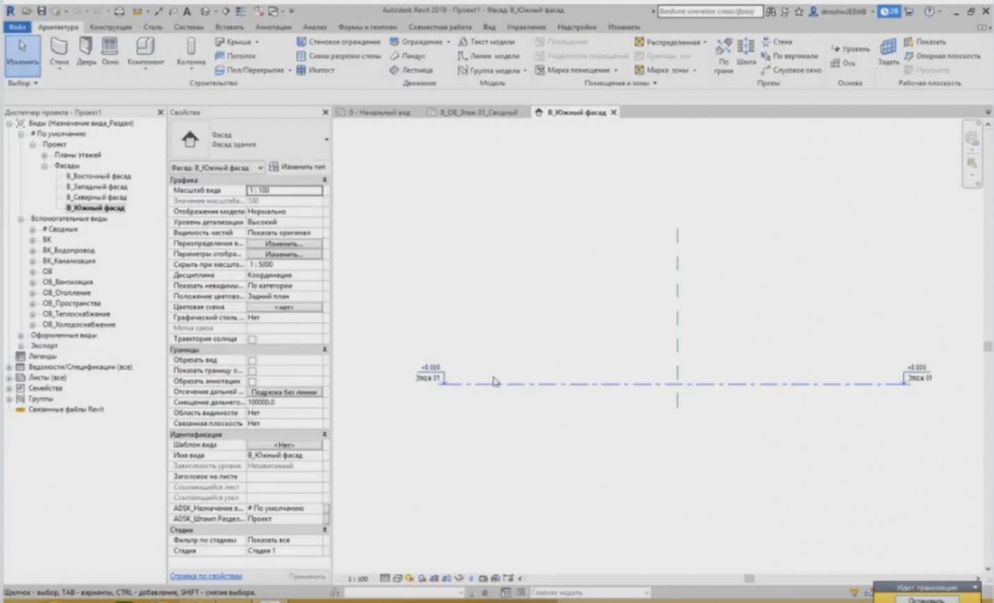
– Next, go to Revit. What do we have? In the “Facade” projection, the level plane is a simple line.
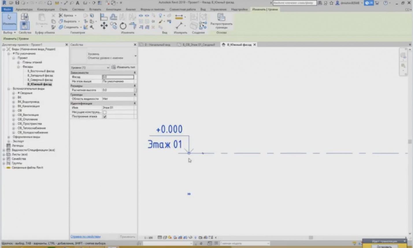
– Any plane has its boundaries, and the boundaries of the plane are these points. You can poorly see them, but there is a text “3D” below, meaning that the level line is a 3D object on the plane and its boundaries end in this point. There is no further plane. And it is the same on the other side.
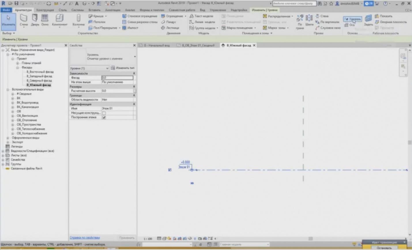
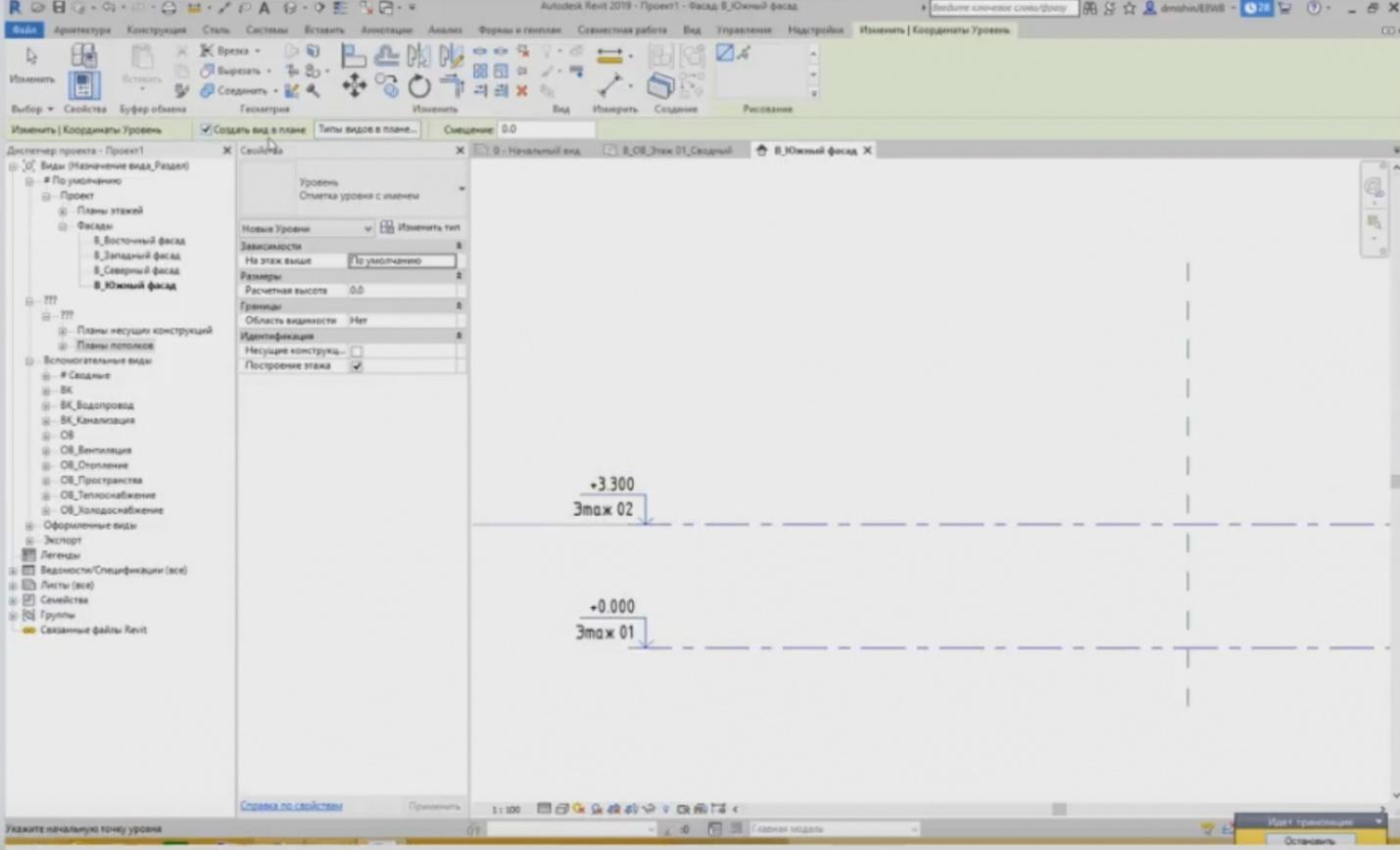
– Let me show you how to create levels. This is not difficult. We go to the “Architecture” tab. There are two tools we are going to study today, i.e. axis and level. Press “Level”. The cursor's icon changes into the crossing. Revit offers to “Set Level Start Point”. In the lower left corner, Revit always indicates what we have to do. It is better to avoid creating levels randomly but place them below each other and thus align their boundaries. If, for example, you have 3.3 meters between the floors, and you have to draw evenly and start doing that under the place where the previous level ends. This is the way it should be.
– We assign start and end points. Why do we have to do it like this? This is convenient because now, if we need to stretch these planes, these levels, when, for example, the building has occurred to be much more, then I can just choose a level, press the “circle” that indicates the end of the level plane boundary, and drag it to the required position. And all other levels with the aligned plane boundaries will also stretch after it. You do not need to pull each level separately. When you create a level, then a set of views is created automatically based on this level.

– Where can we look at it? As soon as we created “Floor 02”, a tab with questions appeared in the Project Browser. If we open it, the “Bearing Structure Plan”, “Ceiling Plan” will appear here among other things; and one more plan should appear in addition to these two views. The plans are always based on a level. What are the plans specific features? The plans cannot be created for no reason, as they are always tied to the level. It means that if you, for example, need to create the plan for the 31st or the 50th floors, then you have to create the level for this plan, e.g., at the mark of 100 meters. And only then, based on this level, you can create these plans.
– Let's have a look again: why the “Bearing Structure Plan” and “Ceiling Plan” have been created? Press the “Level” button to create another level. When you create the level, the “Create a Plan View” button becomes available. If we untick it, then no plans will be created based on this level.
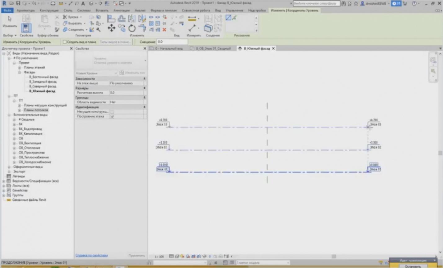
– I am creating the third floor. I have created it but no new plans have been added.
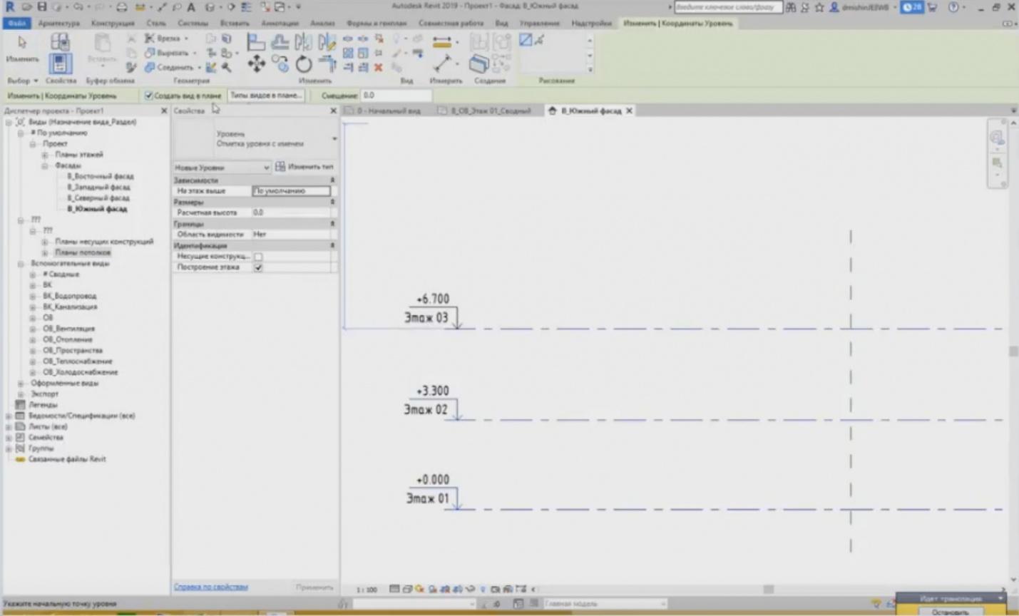
– Let's create one more level. If we need to set the particular plan types, we have to place in the “Project Browser”, e.g., we do not need the ceiling plan, we do not need the bearing structures, but we need anything else, then we have a “Plan View Types” button.
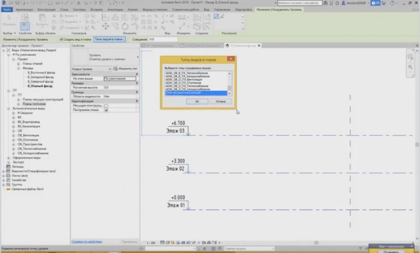
– Press the button, and you will see, what plan types can be created. It can be seen here that the previous level of the second floor; the creation of the ceiling plan and the bearing structure plan were applied to it; this is exactly what we saw. And we need to create, e.g., based on the fourth level, not just the ceiling or bearing structures plans, but all plans for the HV section. I want to create ventilation, heating, heat supply and cold supply. Press OK.
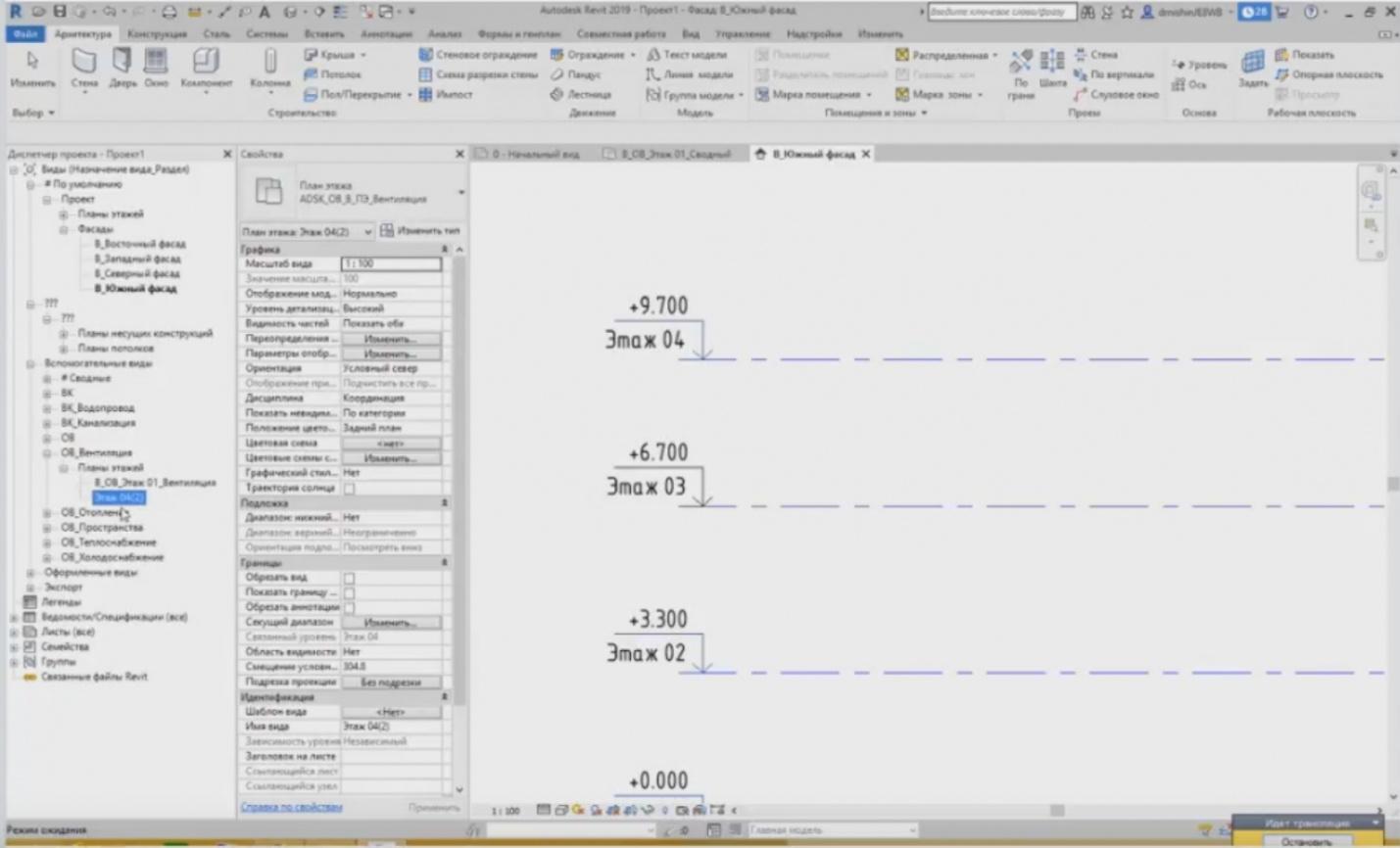
– Only now, I have applied the settings. We are creating the “Floor 04” plan. I have created the level. Let's look at it. The ceiling and bearing structure plans have been added. Go to the “Auxiliary Views” in the HV view. This is our ventilation plan for the fourth floor, heating plan for the fourth floor, etc. All of these plans have been created. Now, when they are created, a unique value “Floor 04(3)” is assigned to them.
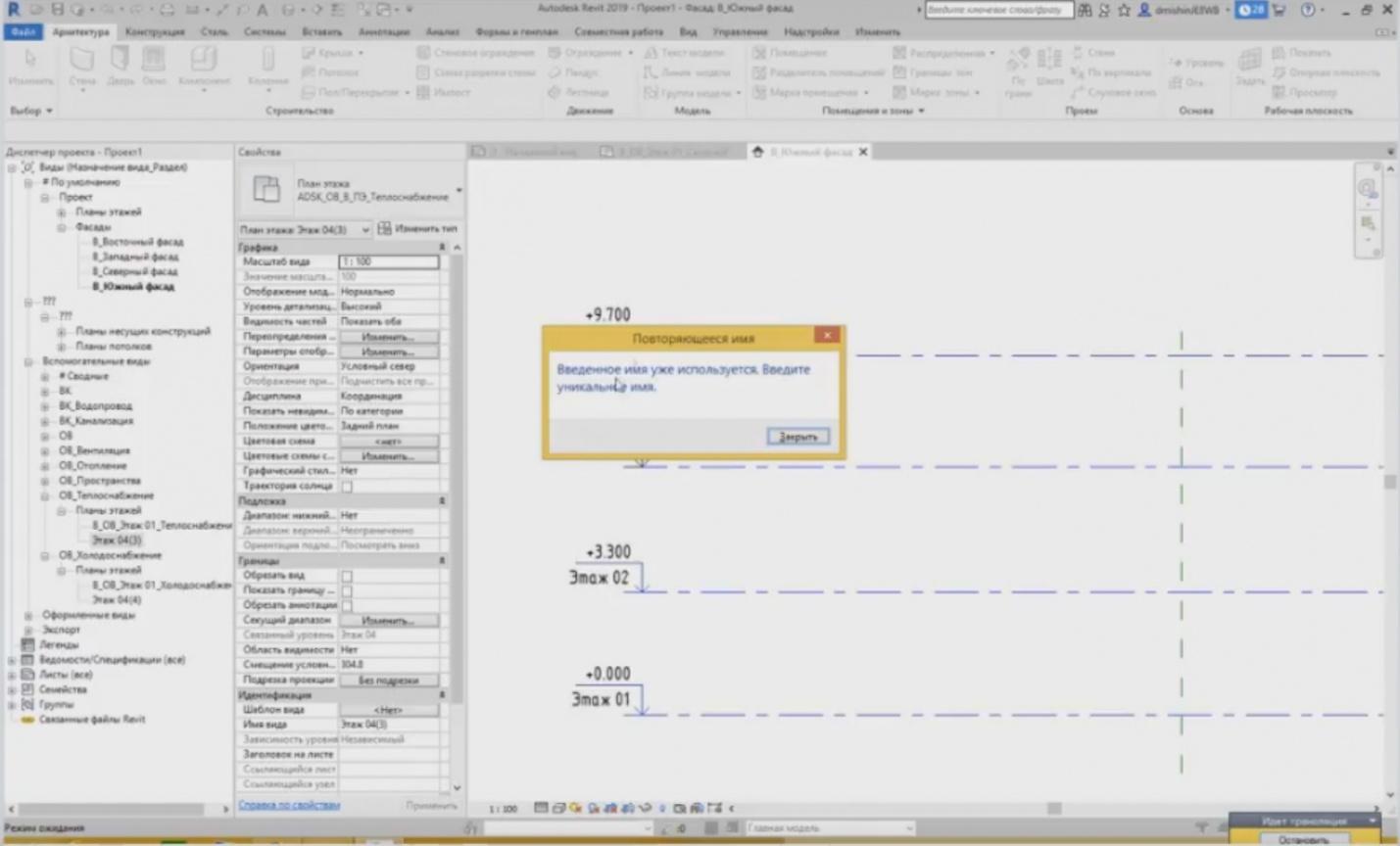
– It cannot be that several plans have the same name. If I rename them, e.g., the cold supply part that is now called “Floor 04(4)”; let's rename heat supply with the same name, and Revit will issue an error stating that this name is already in use and you should enter a unique name. Each view category must have unique values. But this really works if you have ceiling plans and floor plans. The same names can be used here, because these are different element categories in Revit. We have “Floor 02” in the ceiling plan category and, for example, I can create another “Floor 02” in the floor plans.
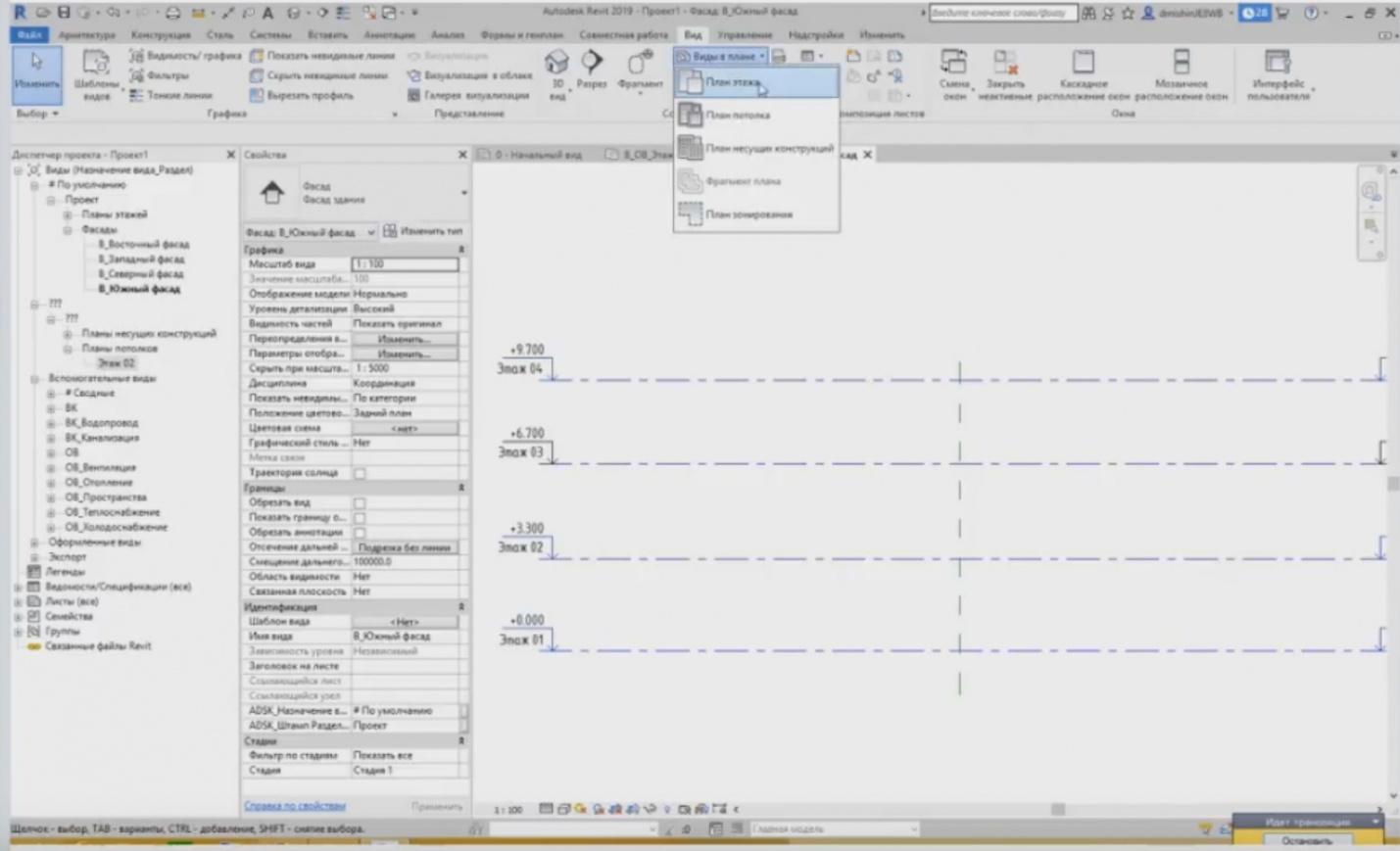
– For example, if we had no time to set the views when creating a level, what view types do we need? If you have forgotten or have not ticked this mark, what should you do at this point? For example, I have “Floor 02”, for which the ceiling plan and the bearing structure plan have only been created. I go to the “View” tab and use the “Plan Views” button.
Next page >>
slides from 3 to 4
Related Articles:
 Webinar «Software structure and general concepts of revit», page 2
 Webinar «Software structure and general concepts of revit», page 3
 Webinar «BIM design in Revit. Getting started», page 2
 Webinar «BIM design in Revit. Getting started», page 3