The 4th webinar about Surge Protection
Webinar text. Page 2
Quick slide navigation:
1. Rules of surge suppressors selection
2. About Miroslaw Zielenkiewicz
3. Lightning Electromagnetic Pulse Protection
4. Thunderstorm Electromagnetic Pulse Protection
5. Electromagnetic environment (IEC 50155)
6. Protected device with surge suppressor
7. Object geometry
8. Surge suppressor at the cable entry of the object
9. Two-stage protection system of signalling link
10. Stage 1. Determination of device stability
11. Example for railway devices
12. Table of port stability
13. Stage 2. Master data definition
Page 2:
14. Basic technical data of the electronic system
15. Differential and longitudinal interference
16. Wave impedance of signalling link
17. Stages 3 and 4 of protection devices selection
18. Gas-filled arrester
19. Energy Distribution of Surge Arrester
20. Multi-stage circuits
21. State standard IEC 61643-21-2014
22. Stage 5. Determination of the number of protective degrees
23. Stage 6. Determination of maximum allowable voltages
24. Stage 7. Determination of the method of signal transmission
25. Stage 8. Determination of the maximum signal voltage
26. Stage 9. Determination of the nominal frequency of operating signals
27. Stage 10. Selection of surge protection circuit
28. Stage 11. The choice of the method of grounding the device
29. Indirect grounding of the screen
30. Stage 12. Estimation of device connections
31. Examples of surge protection
32. Security and alarm system protection
33. Layout of security elements
34. Protection of the central point
35. Microwave barrier protection
36. Protection circuit of the microwave barrier
37. CCTV security protection
38. Surge protection of the video cameras
39. Protection circuit of the CCTV security
40. Protection of a video camera
41. Protection circuit of the CCTV
42. Surge protection of multiplexer
43. SPDs for the protection of the CCTV
44. Light pole with video camera
45. Protection circuit of the RST-safe CCTV
46. Installation manual of the arrester in the shield
47. 75 Ohm video signal lines
48. RST-safe CCTV
49. Example of the video camera protection on the roof
50. Surge protection of sports facilities
51. Football stadium, 2004
52. Loudspeaker outriggers
53. Surge protection shield
54. Operation of protecion elements
55. Light indicator as a fault signalling
56. Surge protection of extensive systems
57. Surge protection of perimeter security
58. Perimeter protective belt
59. Cable laying under the ground
60. Perimeter protection of alarm system
61. Example of the object - tower
62. Microwave barrier
63. Examples of internal device protection
64. Protection circuit of the alarm system board
65. Final protection circuit without primary protection
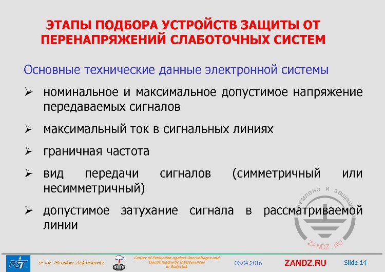
Basic technical data of the electronic system
| ЭТАПЫ ПОДБОРА УСТРОЙСТВ ЗАЩИТЫ ОТ ПЕРЕНАПРЯЖЕНИЙ СЛАБОТОЧНЫХ СИСТЕМ | STAGES TO CHOOSE SURGE PROTECTION DEVICES FOR LOW-CURRENT SYSTEMS |
| Основные технические данные электронной системы | Basic technical data of the electronic system |
| номинальное и максимальное допустимое напряжение передаваемых сигналов | rated and maximum allowable voltage of transmitted signals |
| максимальный ток в сигнальных линиях | maximum current in signalling lines |
| граничная частота | threshold frequency |
| вид передачи сигналов (симметричный или несимметричный) | signal transmission mode (symmetrical or unsymmetrical) |
| допустимое затухание сигнала в рассматриваемой линии | allowable signal attenuation in the concerned line |
— The main ones are the rated and maximum allowable voltage of the transmitted signals, the maximum current in the signal lines, the threshold frequency, the signal transmission mode (symmetrical or unsymmetrical), the allowable signal attenuation in the concerned line. If we look at the first one, rated and maximum allowable voltage of the transmitted signals, if the designer takes into account only the rated voltage, then we will have the same situation, that we had at the time when we got an order for an element for loudspeaker systems. And the loudspeakers stopped working at a large stadium at a certain volume. This means that the voltage was higher than rated voltage, not 110 V, but 115-120-130 V, and this simply led to the activation of protective elements.
Differential and longitudinal interference
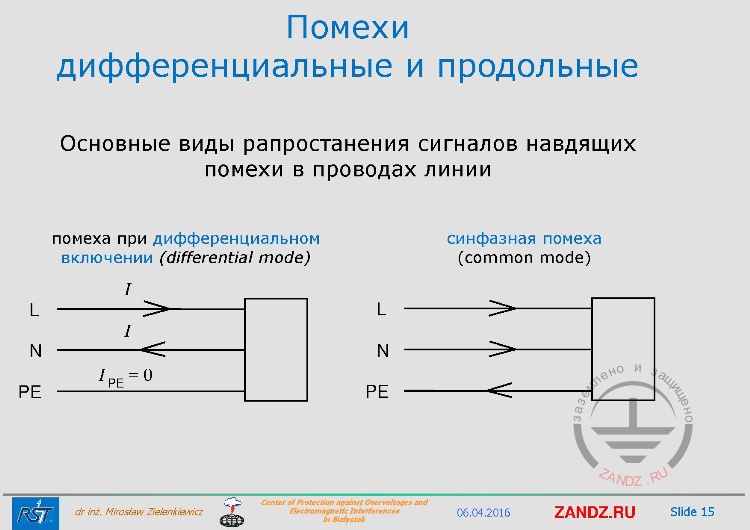
| Помехи дифференциальные и продольные | Differential and longitudinal interference |
| Основные виды рапростанения сигналов навдящих помехи в проводах линии | The main types of the propagation of signals interfering in the wires of the line |
| помеха при дифференциальном включении (differential mode) | transient in differential mode |
| синфазная помеха (common mode) | transient in common mode |
— The main type are differential and longitudinal signal transmissions in relation to the grounded conductor, whether the current flows in this conductor, or does not flow. Therefore, when the manufacturers of ultrasonic testing devices consider such circuits they are well aware of this, and may select a little different schematic circuits. Designers rarely need this information.
Wave impedance of signalling link
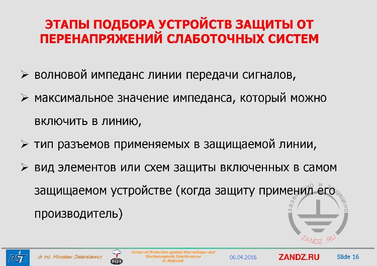
| ЭТАПЫ ПОДБОРА УСТРОЙСТВ ЗАЩИТЫ ОТ ПЕРЕНАПРЯЖЕНИЙ СЛАБОТОЧНЫХ СИСТЕМ | STAGES TO CHOOSE SURGE PROTECTION DEVICES FOR LOW-CURRENT SYSTEMS |
| волновой импеданс линии передачи сигналов | wave impedance of signalling link |
| максимальное значение импеданса, который можно включить в линию | maximum impedance that can be included in the line |
| тип разъемов применяемых в защищаемой линии | type of connectors used in the protected line |
| вид элементов или схем защиты включенных в самом защищаемом устройстве (когда защиту применил его производитель) | type of protection elements or circuits included in the protected device itself (when the manufacturer applied protection) |
— The next elements are, for example, the wave impedance of signal transmission that is necessarily related to a coaxial minimum. We must understand that this is either 50 or 75 Ohm, or invented - this is very rare, the wave line impedance. If we set the impedance orher than the rated, then we can just suppress the signal. The maximum impedance that we can include into this line. Very simple, but very important information, when we design protection, we need to consider the type of connectors used in the protected line. Anyone who has worked with coaxial lines knows that there are different standards for connectors NB, BNC, and so on. If we install the wrong type or if we install not female, but male type, then the system just will not work. I heard about this case when the customer first ordered about 1500 pieces, and these 1500 pieces could not be connected, only because the connectors did not fit. Someone did not know what he was doing. It seems simple, but you can always make a mistake. A very important protection type or protection circuit is the one included into the protected device itself, when the manufacturer of the protected device applied protection. So, we must remember that we must coordinate the energy between the next stages of protection. And if we do not have this information, which happens often, it may turn out that the protection circuit we have not event known about in this device will trigger, and the circuit that we have installed earlier because of the inductance mismatch between these two cascades of surge protection system will not work. Therefore, we must always aim to get this information. If we do not have this information, we must apply a circuit with an additional inductor at the output of the SPD.
Stages 3 and 4 of protection devices selection
|
ЭТАПЫ ПОДБОРА УСТРОЙСТВ ЗАЩИТЫ ОТ |
STAGES TO CHOOSE SURGE PROTECTION DEVICES FOR LOW-CURRENT SYSTEMS |
|
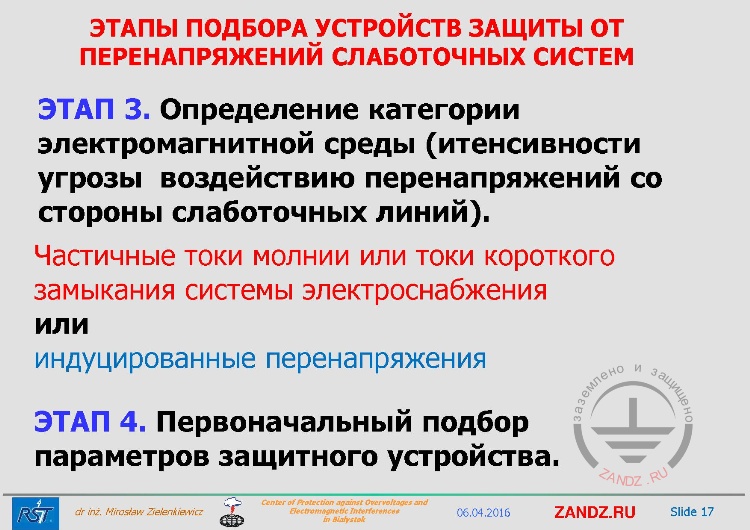
ЭТАП 3. Определение категории электромагнитной среды (итенсивности угрозы воздействию перенапряжений со стороны слаботочных линий) |
STAGE 3. Determination of the category of the electromagnetic environment (the intensity of the threat of overvoltage of low-current lines) |
|
Частичные токи молнии или токи короткого замыкания системы электроснабжения или индуцированные перенапряжения |
Partial lightning currents or short-circuit currents of the power supply system or induced overvoltages |
|
ЭТАП 4. Первоначальный подбор параметров защитного устройства |
STAGE 4. The initial selection of the parameters of the protective device |
— The next stage is to determine the category of the electromagnetic environment, in other words, what is the intensity of the threat of overvoltage of low-current lines in a certain place. If we know that we are dealing, for example, with the railway, where there are very long distribution mains, then they go alongside the railway. Something is constantly induced in them from the current flowing into the wire of the supply locomotive or in the rails, so in this situation we must provide a very high level of protection for the devices.
Gas-filled arrester
| ЭТАПЫ ПОДБОРА УСТРОЙСТВ ЗАЩИТЫ ОТ ПЕРЕНАПРЯЖЕНИЙ СЛАБОТОЧНЫХ СИСТЕМ | STAGES TO CHOOSE SURGE PROTECTION DEVICES FOR LOW-CURRENT SYSTEMS |
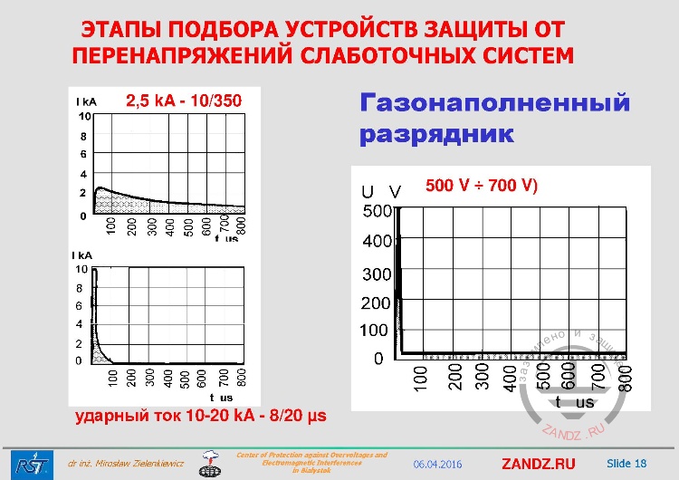
| Газонаполненный разрядник | Gas-filled arrester |
| ударный ток 10-20 kA - 8/20 μs | surge current 10-20 kA - 8/20 μs |
— When we already have this information, we proceed to the next stage, in other words, we initially select the parameters of the protective device and look at the parameters, we find them in the manufacturers catalogs. For example, we must understand that if we are dealing with partial lightning currents then we always look at a 10/350 μs pulse. If the object does not have a lightning protection system, then we look at an 8/20 µs pulse. The question is: what do we do with the railway, where there's no such lightning protection? Here, a little more knowledge is needed because it seems that along the railway the protection system is not installed, but if it is electrified then the traction wire itself and the entire wire construction that hangs over the rails is already a lightning protection system, whether we want it or not. This is when we need to figure out a little more about where our device will be found or accept such a systematics of 8/20 μs, or just stick to our knowledge and expect that a partial lightning current will flow. In an object that has a lightning protection system, knowing that we have determined that lightning can get into the object, we must protect it, we always use elements with a pulse of 10/350 μs at the cable entry. And today, if we take a look at the catalogs, then 2.5 kA 10/350 μs are the parameters that we can get for our overvoltage protection elements. Why is it not 10 kA, not 50 kA, not 20 kA, as in the power supply network?
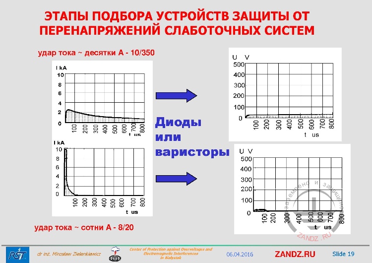
Diodes or varistors
| удар тока ~ десятки A - 10/350 | current rush ~ tens of amperes - 10/350 |
| Диоды или варисторы | Diodes or varistors |
| удар тока ~ сотни A - 8/20 | current rush ~ hundreds of amperes - 8/20 |
— Then we must install the following cascades with diodes or varistors. But it is clear that diodes and varistors may not withstand such energies in these cases, so we must use multi-stage circuits, which we have already mentioned several times.
Multi-stage circuits
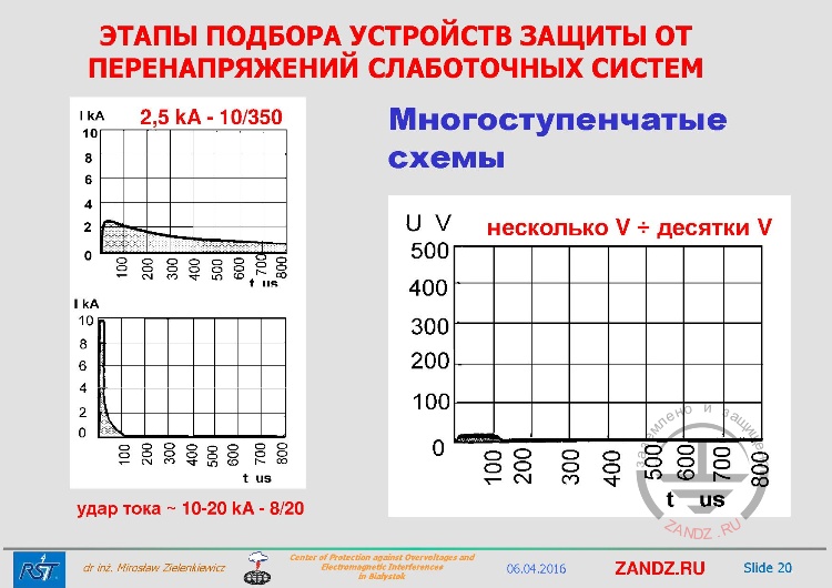
| Многоступенчатые схемы | Multi-stage circuits |
| несколько V ÷ десятки V | a few volts ÷ tens of volts |
| удар тока ~ 10-20 kA - 8/20 | current rush ~ 10-20 kA - 8/20 |
— So, this scheme, even if it is affected by a parial lightning current, gives a very small pulse at the input, which leaks to our protected device. Its energy is negligible and in no way can damage our device. We select the voltage level by the limiting level, basically a diode is installed here at the end, and as we know, the diode is semiconductor element made of monocrystalline silicon and it is very easy to select the voltage parameters. It is possible to buy a diode for any voltage and very carefully select the right one for our protected circuit, so we must take into account whether we are designing single-stage or multi-stage schemes in the current object.
State standard IEC 61643-21-2014
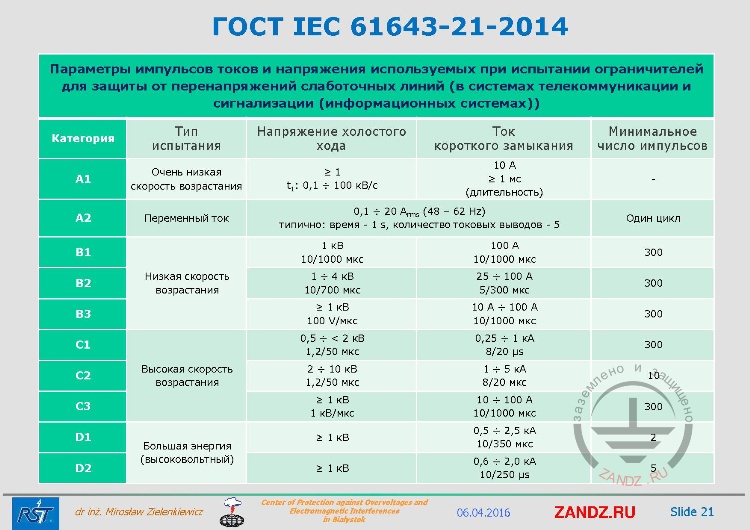
| Параметры импульсов токов и напряжения используемых при испытании ограничителей для защиты от перенапряжений слаботочных линий (в системах телекоммуникации и сигнализации (информационных системах)) | Parameters of current and voltage pulses used in testing limiters for surge protection of low-current lines (in telecommunication and signaling systems (informations systems)) |
| Категория | Category |
| Тип испытания | Type of test |
| Напряжение холостого хода | No-load voltage |
| Ток короткого замыкания | Short-circuit current |
| Минимальное число импульсов | Minimum number of pulses |
| Очень низкая скорость возрастания | Very low rise rate |
| Переменный ток | Alternating current |
| Низкая скорость возрастания | Low rise rate |
| Высокая скорость возрастания | High rise rate |
| Большая энергия (высоковольтный) | High energy (high voltage) |
| Один цикл | One cycle |
| типично: время - 1 s, количество токовых выводов - 5 | typically: time - 1 s, number of current outputs - 5 |
— And how should we choose them? What is the definitive factor? If you have this standard, this is an international standard, in Europe this is EN that shows how to test surge protection devices. It is written here: about low-current lines in telecommunication and alarm systems, information systems. And there are the categories for which this SPD is being tested, and if we are dealing with a partial lightning current. Please look at this table, we see this parameter, then the category should be D1. If we are dealing with induced effects, then we select elements that have a pulse of 8/20 μs. And SPDs manufacturers specify these categories in their catalogs. That is, this is the basic knowledge that the designer must have. When, where and what signal standards are used, I do not have time to talk about it today. But just look at the current parameters, voltage parameters, they are different. In Europe a pulse of 8/20 and 10/350 µs is mostly used. And here the category D1, D2 is called the high energy category or high voltage category. There are categories with a high rise rate of pulse, this means inductive effects and with a low rise rate. There is a category where we test the effect of alternating current or a category with a very low rise rate. When we look in the catalog we have to look at the category. We are mainly interested in categories D or C.
Stage 5. Determination of the number of protective degrees in signalling link
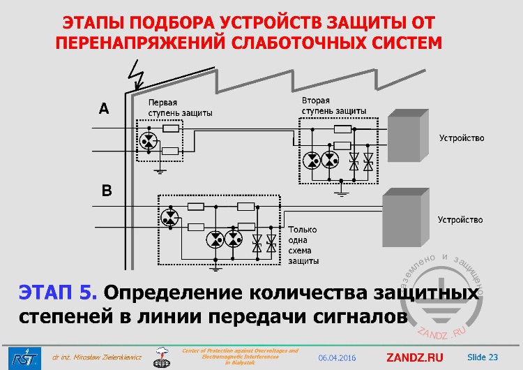
| Первая ступень защиты | First stage of protection |
| Вторая ступень защиты | Second stage of protection |
| Устройство | Device |
| Только одна схема защиты | Only one protection scheme |
| ЭТАП 5. Определение количества защитных степеней в линии передачи сигналов | STAGE 5. Determination of the number of protective degrees in signalling link |
— At the next stage we define something that I have mentioned earlier at the beginning of today's webinar. How many stages will our overvoltage protection system have? And the principle is simple here, if we have a zone protection concept, then we install separate protection elements on the boundary of each zone. If we do not use such zone concept, but we take into account the length of the cables, I will give you an example of such object where I use such cascades, although I haven't managed to construct a zone concept of lightning protection in such object. When we had the border points upgraded, we adapted the existing facilities for customs. As you know we are at the border of Schengen zone. And in such customs facility there is a lot of computer systems now that process a lot of signals that will remember forever what Ivan or Miroslav transported today or tomorrow and what he declared. To somebody it is not clear, but the systems are huge, expensive. And in this case the object of length is about 100 m, because trucks are examined inside, has received a new lightning protection system. But this object was shared between customs and the existing woodworking plant where they simply cut the tree into boards.
Stage 6. Determination of the maximum allowable operating voltages of signals
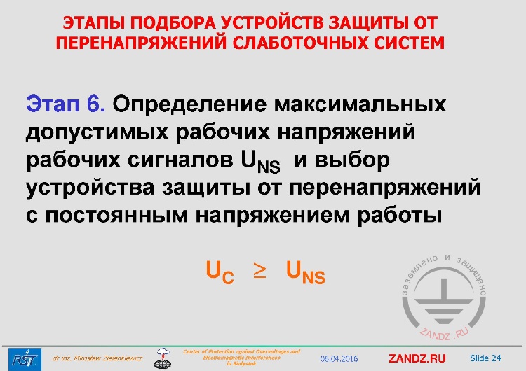
| Этап 6. Определение максимальных допустимых рабочих напряжений рабочих сигналов UNS и выбор устройства защиты от перенапряжений с постоянным напряжением работы | Stage 6. Determination of maximum allowable operating voltages of working signals UNS and selectioin of SPD DC |
— An important stage is to determine the maximum allowable operating voltages and select SPD with direct current greater than this maximum allowable operating voltage. Making a mistake at the moment may mean the following. If we look close at the parameters of the protected system, in some mode it may turn out that this voltage will be greater than the rated voltage of our device and then our arrester will work and cut working signals. No one needs it, it is a costly mistake.
Stage 7. Determination of the method of signal transmission
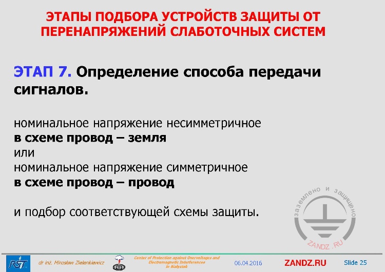
| ЭТАП 7. Определение способа передачи сигналов | STAGE 7. Determination of the method of signal transmission |
| номинальное напряжение несимметричное | unsymmetrical rated voltage |
| в схеме провод – земля | in the circuit wire-ground |
| или | or |
| номинальное напряжение симметричное | symmetrical rated voltage |
| в схеме провод – провод | in the circuit wire-wire |
| и подбор соответствующей схемы защиты | and selection of appropriate protection scheme |
— If we look at signal transmission we just have to understand that it mainly matters for the manufacturer, not that much for the designer. But you must remember that such operating current can flow in a wire-ground circuit. And in practice it is important at the SPDs design stage.
Stage 8. Determination of the maximum allowable voltage of working signals
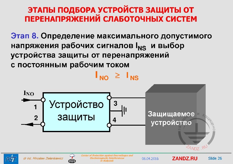
| Этап 8. Определение максимального допустимого напряжения рабочих сигналов INS и выбор устройства защиты от перенапряжений с постоянным рабочим током | Stage 8. Determination of maximum allowable operating voltage of INS working signals and selectioin of SPD DC |
| Устройство защиты | Protection device |
| Защищаемое устройство | Protected device |
— The current that flows here between the device, we see, for example, i the current INO. If in our protection device between the cascades appears a sequential element, some kind of thyristor or resistor. Resistor that does not withstand the rated current of 1, 2, 3, 6 A, it happens sometimes. It is just that with this mode of operation of our device our SPD will burn out and stop working. Therefore, it is very important at the selection stage.
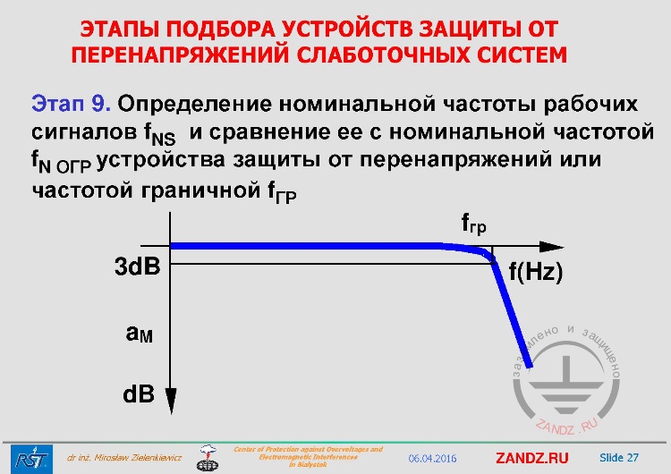
Stage 9. Determination of the nominal frequency of working signals
| Этап 9. Определение номинальной частоты рабочих сигналов fNS и сравнение ее с номинальной частотой fОГР устройства защиты от перенапряжений или частотой граничной fГР | Stage 9. Determination of the nominal frequency of working signals fNS and its comparison with the nominal frequence of the surge protection device fSPD or the edge frequency fEDGE |
— The frequency range of devices is a whole another story. In practice, the maximum frequency range for the 3 dB level is indicated. And for an ordinary electrician or designer this information is enough. For special systems it is necessary to have more knowledge, and full characterization is necessary, but basically this data are sufficient. Here we have such parameters that at the level of 1-10-100 MHz we get too much signal attenuation and our device is not suitable abouve this frequency, so we should always check the frequencies of this signal are. Those who know this understand that this can be expressed by the data bit rate in Mb must be able to recalculate and select the parameters, having seen them in the manufacturer's catalog, so that the operation of our protected system was not affected.
<< Previous page
slides from 1 to 13
Next page >>
slides from 27 to 39
Useful materials for designers:
- Webinars with leading industry experts
- Everything for calculations of grounding and lightning protection
- Useful materials: articles, recommendations, examples
Related Articles:


