The 4th webinar about Surge Protection
(took place on 6 April 2016 at 11:00 a.m. Moscow time)
Equipment used in low signal systems, for example:
- in data transmission, measurement and control systems
- in automation and alarm systems
- in security and fire alarm systems
- in emergency voice alarm communication systems
- in video surveillance systems
- in radio communication systems
It is recommended to view with the quality of 720p in full screen mode.
Generally, characterized by a low level of electromagnetic resistance from the part of its signal interfaces. This is primarily due to the use in such systems of an increasing number of electronic circuits that are sensitive to electromagnetic interference. Overvoltages caused by lightning strikes or interference in the power supply network are especially dangerous for such devices. They may damage or even destroy electronic devices. The corresponding losses do not relate only to the material (the need for repair or replacement of equipment), but they usually include additional costs associated with the loss of system functionality that includes a failed module or an entire electronic device resulting in a loss of company reputation because of interruptions in its work.
To ensure high reliability of various types of low-current systems operating under conditions of a significant level of electromagnetic interference, it is necessary to use overvoltage protection circuits (SPDs) selected according to the standard of the protected interface, as well as with the expected level of interference (partial lightning currents or induced overvoltage currents). Such SPDs should limit overvoltage to safe levels maintained by the protected device without losing the nominal functional properties of the system.
The presentation will also consider examples of ways to protect existing low-voltage systems, taking into account the principles of zonal protection concept in accordance with the requirements of the IEC 62305 standard.
Webinar text. Page 1
Quick slide navigation:
Page 1:
1. Rules of surge suppressors selection
2. About Miroslaw Zielenkiewicz
3. Lightning Electromagnetic Pulse Protection
4. Thunderstorm Electromagnetic Pulse Protection
5. Electromagnetic environment (IEC 50155)
6. Protected device with surge suppressor
7. Object geometry
8. Surge suppressor at the cable entry of the object
9. Two-stage protection system of signalling link
10. Stage 1. Determination of device stability
11. Example for railway devices
12. Table of port stability
13. Stage 2. Master data definition
14. Basic technical data of the electronic system
15. Differential and longitudinal interference
16. Wave impedance of signalling link
17. Stages 3 and 4 of protection devices selection
18. Gas-filled arrester
19. Energy Distribution of Surge Arrester
20. Multi-stage circuits
21. State standard IEC 61643-21-2014
22. Stage 5. Determination of the number of protective degrees
23. Stage 6. Determination of maximum allowable voltages
24. Stage 7. Determination of the method of signal transmission
25. Stage 8. Determination of the maximum signal voltage
26. Stage 9. Determination of the nominal frequency of operating signals
27. Stage 10. Selection of surge protection circuit
28. Stage 11. The choice of the method of grounding the device
29. Indirect grounding of the screen
30. Stage 12. Estimation of device connections
31. Examples of surge protection
32. Security and alarm system protection
33. Layout of security elements
34. Protection of the central point
35. Microwave barrier protection
36. Protection circuit of the microwave barrier
37. CCTV security protection
38. Surge protection of the video cameras
39. Protection circuit of the CCTV security
40. Protection of a video camera
41. Protection circuit of the CCTV
42. Surge protection of multiplexer
43. SPDs for the protection of the CCTV
44. Light pole with video camera
45. Protection circuit of the RST-safe CCTV
46. Installation manual of the arrester in the shield
47. 75 Ohm video signal lines
48. RST-safe CCTV
49. Example of the video camera protection on the roof
50. Surge protection of sports facilities
51. Football stadium, 2004
52. Loudspeaker outriggers
53. Surge protection shield
54. Operation of protecion elements
55. Light indicator as a fault signalling
56. Surge protection of extensive systems
57. Surge protection of perimeter security
58. Perimeter protective belt
59. Cable laying under the ground
60. Perimeter protection of alarm system
61. Example of the object - tower
62. Microwave barrier
63. Examples of internal device protection
64. Protection circuit of the alarm system board
65. Final protection circuit without primary protection
Approximate Reading Time: 1 hour 26 minutes.
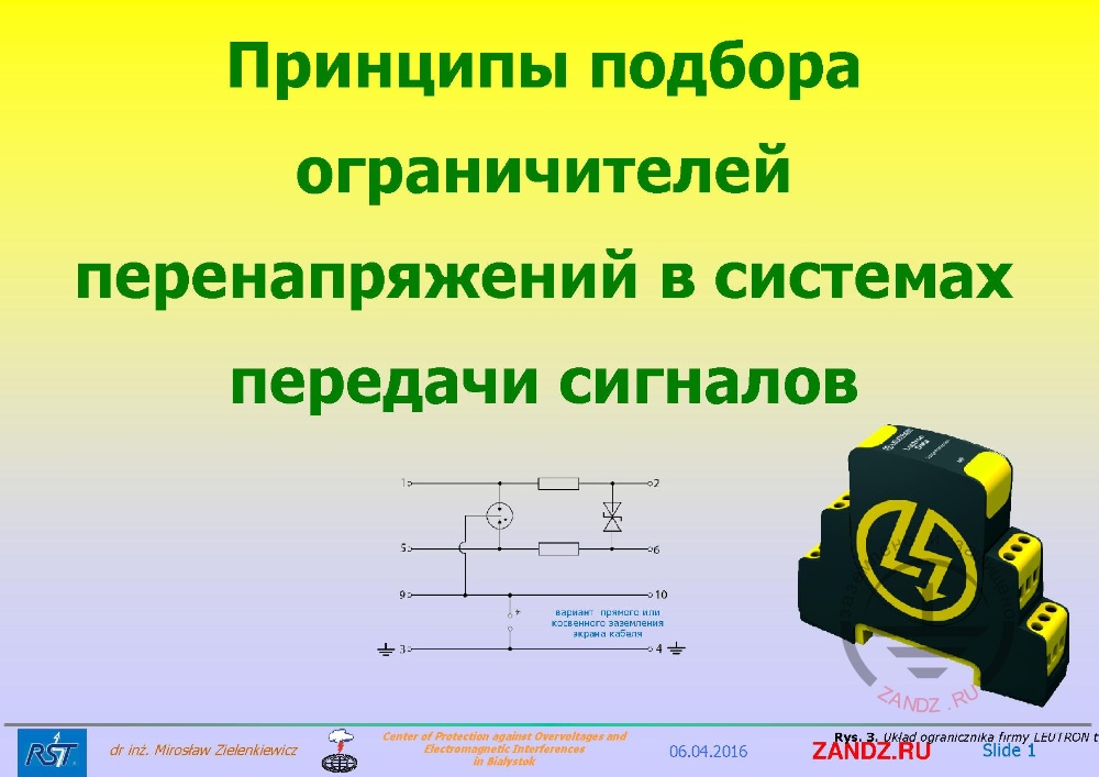
Rules of surge suppressor selection in signalling transmission systems
| вариант прямого или косвенного заземления экрана кабеля | direct or indirect grounding option for cable shield |
— Hello, colleagues! Hello, Miroslaw! Welcome to our next online event. This is our fourth meeting of Surge protection series. You can watch the video of the previous webinars, as well as register for new ones, you may click the link that I send you every time in the chat. Let me remind you that at previous meetings we discussed in detail the zonal concept of lightning protection, since all protection schemes are build on it,as well as the differences in surge protection devices. And in previous webinars we talked about the protection of 230/400V, 50 Hz power supply lines. Today we have the first part of "Surge protection of low-current lines". The topic is interesting, popular and raises many questions about how to properly organize protection. Today we will talk about this, consider examples and measures necessary for protection devices layout.
About Miroslaw Zielenkiewicz
— The lecturer of this webinar is still a recognized expert in the field of lightning protection, Miroslaw Zielenkiewicz. On the slide you can see some of his merits and awards, but believe me - these are not all of them. My name is Aleksei Korytko. I am the webinar administrator and I will answer your questions and comments which you can leave in the chat at the bottom left. We will try to answer the question at the end of the webinar that will last from 60 to 90 minutes. Also the presentation may have schemes with fine details, you can use a special magnifying glass tool to see them all. It is located down below the presentation window. I think that organizational part is over. I am pleased to hand over the word to Miroslaw. Miroslaw, good afternoon!
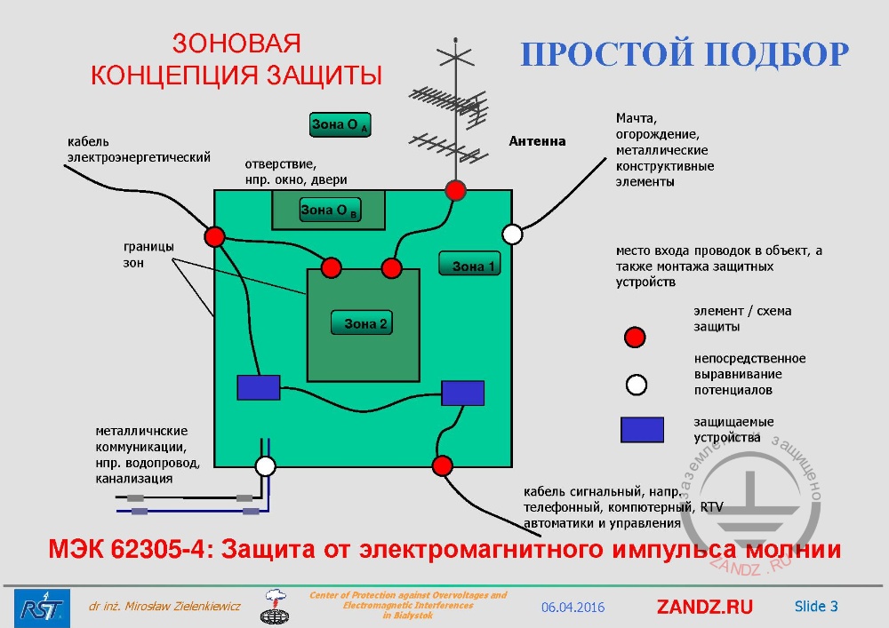
IEC 62305-04: Lightning Electromagnetic Pulse Protection
| ПРОСТОЙ ПОДБОР | SIMPLE SELECTION |
| ЗОНОВАЯ КОНЦЕПЦИЯ ЗАЩИТЫ | ZONAL PROTECTION CONCEPT |
| Зона | Zone |
| Кабель электроэнергетический | Electric cable |
| отверствие, например, окно, двери | Aperture, for example, a window, doors |
| Границы зон | Boundaries of the zones |
| Металличнские коммуникации, например, водопровод, канализация | Metal construction, for example, water pipeline, water carriage |
| Антенна | Antenna |
| Мачта, огорождение, металлические конструктивные элементы | Tower, guard rail, metal construction elements |
| место входа проводок в объект, а также монтажа защитных устройств | Entry for cables into an object and for installation of protective devices |
| элемент / схема защиты | Element / protection circuit |
| Непосредственное выравнивание потенциалов | The potential equalization |
| Защищаемые устройства | Protected devices |
| кабель сигнальный, например, телефонный, компютерный, RTV автоматики и управления | Signal cable, for example, telephone cable, computer cable, control cable |
| МЭК 62305-4: Защита от электромагнитного импульса молнии | IEC 62305-4: Lightning Electromagnetic Pulse Protection |
— Good afternoon, my dear colleagues! Thank you, Aleksei, for the introduction. As for my merits, they are important indeed, that is, today I deserve my own, I managed to come from Warsaw not too late to say you a few words. I hope it will be useful for you, which is the most important thing, and then the merits will become real. Today, our conversation will indeed be about the protection of low-current lines. They are very different from the power supply lines, at least on one basis. Usually, the cross-section of the conductors of low-current lines is much smaller and, as I have already mentioned, as more water flows through a pipe of larger diameter, the same way more energy flows through conductors with a larger diameter. Therefore, low-current lines are less resistant to the partial lightning current energy that can leak through such line.
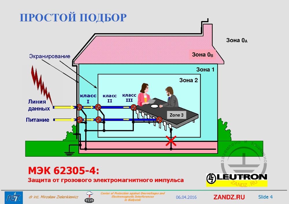
IEC 62305-04: Thunderstorm Electromagnetic Pulse Protection
| ПРОСТОЙ ПОДБОР | SIMPLE SELECTION |
| Экранирование | Shielding |
| Класс I | Class I |
| Линия данных | Data line |
| Питание | Power Supply |
— In this case we cut off not only the power supply lines, but also the data lines, block them from interference into our object by using overvoltage protection elements.
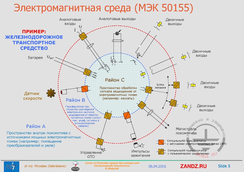
Electromagnetic environment (IEC 50155)
| ПРИМЕР: ЖЕЛЕЗНОДОРОЖНОЕ ТРАНСПОРТНОЕ СРЕДСТВО | EXAMPLE: RAILWAY VEHICLE |
| Батарея | Battery |
| Датчик скорости | Velocity sensor |
| Район A | Area A |
| Пространство внутри локомотива с источниками мощных электромагнитных помех (например: помещение преобразователей и реле) | The space inside the locomotive with sources of powerful electromagnetic interference (for example: room with converters and relays) |
| Управление GTO | GTO Management |
| Импульсы зажигания | Ignition pulses |
| Сигнальный трансформатор с гальваническим разделением | Signal transformer with galvanic isolation |
| Сигнальныйй трансформатор с затуханием электромагнитных помех (ЭМ) | Signal transformer with attenuation of electromagnetic interference (EM) |
| Магистраль локомотива | Distribution main of locomotive |
| Двоичные выходы | Binary outputs |
| Двоичные входы | Binary inputs |
| Аналоговые выходы | Analog outputs |
| Аналоговые входы | Analog inputs |
| Пространство обработки сигнала защищенное от электромагнитных помех (например: кассеты) | Signal processing space is protected from electromagnetic interference (for example: cassettes) |
— Considering any object we must first understand what systems are there in it. For example, I am showing you the locomotive, and things said about it in the standard for its electromagnetic environment. It is perfectly shown here how many and what kinds of different exits there are in such a small object only. If we take the railway in Poland for which we developed surge protection, then you should understand that there are very long data highways that transmit signals along the rail. And if we do not determine first what signals are transmitted there, then we will not be able to protect them. If we do not determine everything exactly. The signal characteristic is what we are going to be talking about today. Having installed a wrong arrester we simply suppress this signal, and on the railway it can lead to an accident. Therefore, you should very carefully know what kind of signal we have. Therefore, we see that we can have an analog output, we can have a digital output, we can have different types of signal standards, two-core, three-core, multi-core, with which we must work. This is what we are going to be talking about today.
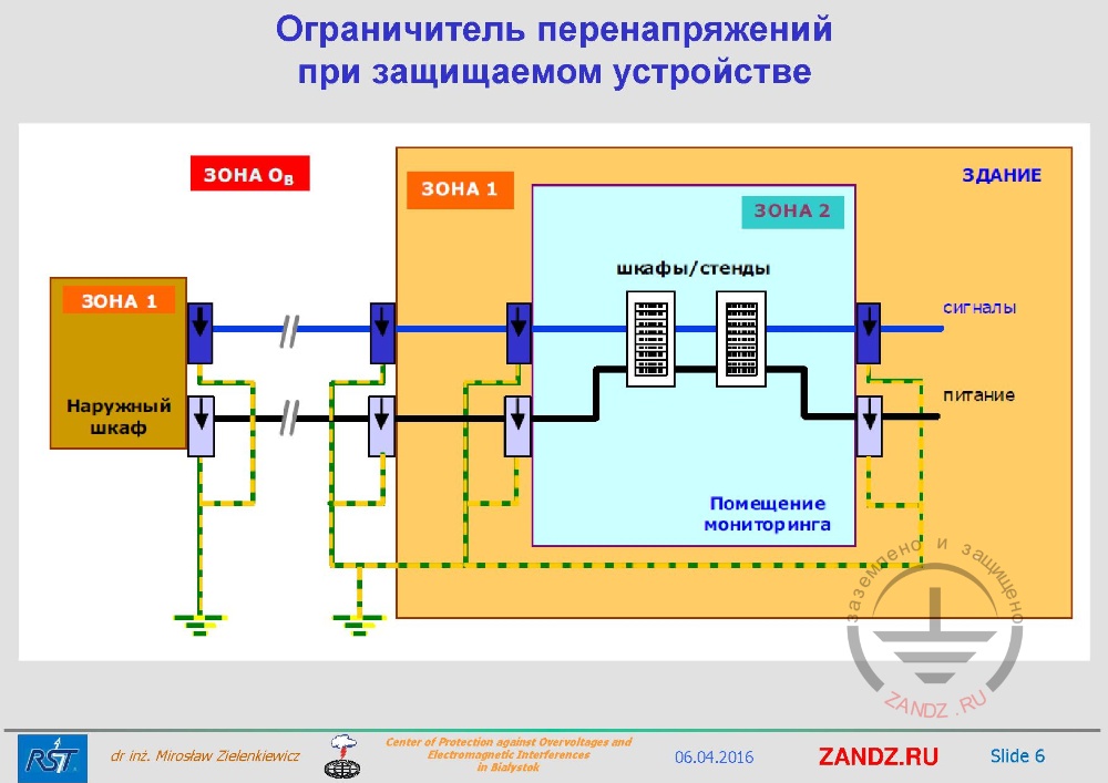
Protected device with surge suppressor
| Ограничитель перенапряжений при защищаемом устройстве | Protected device with surge suppressor |
| Наружный шкаф | Outdoor shield |
| Шкафы/стенды | Shields/benches |
| Здание | Building |
| Сигналы | Signals |
| Питание | Power Supply |
| Помещение мониторинга | Monitoring room |
— We should already know how to install elements of overvoltage protection, because if we use the zonal protection concept, and it, as can be verified in practice, is simply perfect for protection. We see that if the wires enter the object outside, on the border we install protection both for the power supply network on the right, and for the signal lines. If this is an outdoor shield, for example, automation cabinet on a railroad, then the same here, we must install overvoltage protection at the input of all the cores of our power supply and signal lines.
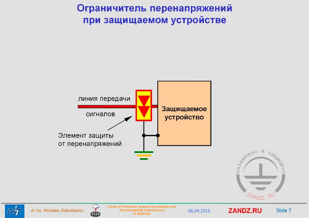
Object geometry
| линия передачи сигналов | signalling link |
| Элемент защиты от перенапряжений | Surge protection device |
| Защищаемое устройство | Protected device |
— And where to install an element, if we look at the geometry of the object, at which point do we have to install an element along the wire? Most often designers install protection devices to save money on just a protected device, expecting the element to protect our system. Assume that the element is installed in about of 10-15 meters from the cable entry to the object. But you have to understand that then the energy that we will divert by our arrester to the ground will flow through our conductor and then through the potential equalization system to ground. And we have a circuit through which that unwanted current flows, but it is large and creates an electromagnetic field around the wires and will interfere to the room in which the wire is laid. Therefore, according to the zonal protection concept, it is better to install it at the cable entry to an object. But I see that not everything is visible to us.
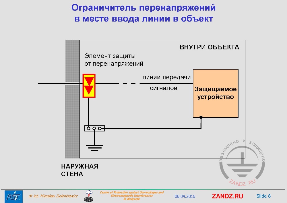
Surge suppressor at the cable entry of the object
| Ограничитель перенапряжений в месте ввода линии в объект | Surge suppressor at the cable entry of the object |
| Элемент защиты от перенапряжений | Surge protection device |
| ВНУТРИ ОБЪЕКТА | INSIDE THE OBJECT |
| НАРУЖНАЯ СТЕНА | OUTSIDE WALL |
— Here on the left there is the wall that looks like a strange object. We install at the cable entry. Always the question is: outside the wall or inside? In practice it does not matter, if we divert this current to earth in a way that it does not interfere the electromagnetic energy to sensitive devices. If there is a danger of it happening, we should definitely do it outside observing all measures for protection from moisture. In this way the system price increases and the system is simplified. I am showing that the connection with grounding is the shortest, because then our limiter will get voltage restriction, and the voltage drop across this inductance on the way to the grounding conductor will be minimum. Please, take a look, there will be a voltage limit at our limiter plus a voltage drop across the inductance of this wire. If we see that these points fit our protected device, then this sum of voltages will give us the voltage after restriction through our device.
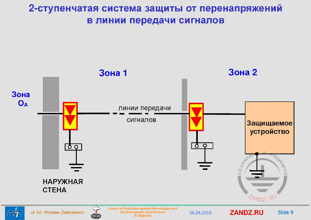
Two-stage protection system of signalling link
| 2-ступенчатая система защиты от перенапряжений в линии передачи сигналов | Two-stage protection system of signalling link |
— If in practice the object already exists, and it is impossible to make a clean perfect zonal concept, then we can definitely use the simplified method that I show here, taking into account that the outer zone is divided from the inner zone by cable cores only, so, overvoltage arrester is installed on cable cores. In such case we do not have room shielding, but we can add it if there is no screen on our cable, or on its route. Either it simply has its own screen, or we additionally hide it in some conductive channels so that it does not radiate electromagnetic energy outside.
Stage 1. Determination of stability of low-current line devices to the effects of overvoltages
| ЭТАПЫ ПОДБОРА УСТРОЙСТВ ЗАЩИТЫ ОТ ПЕРЕНАПРЯЖЕНИЙ СЛАБОТОЧНЫХ СИСТЕМ | Stages to choose surge protection devices for low-current systems |
— How to choose a surge protection device for low-current systems then? First, we must understand that we have different standards of signals, therefore, when we start designing, our first principle is not to change the signal in any way. In any mode of operation of this system our signal must pass the way the designers of this system have designed it. In other words, while dealing with this system we should not change its properties. And then we have to think about how should this element be protected? So, we need to understand what kind of resistance of this system affects overvoltage from the side of low-current lines. And the question is: how to define it? It may be that the designer will each time determine the stability of this system. But at that moment you should apply the standard that I have said. Nothing needs to be invented, nothing needs to be sought, you just need to know. The knowledge in this area now has reached the level at which we can find stability in interference to any system.
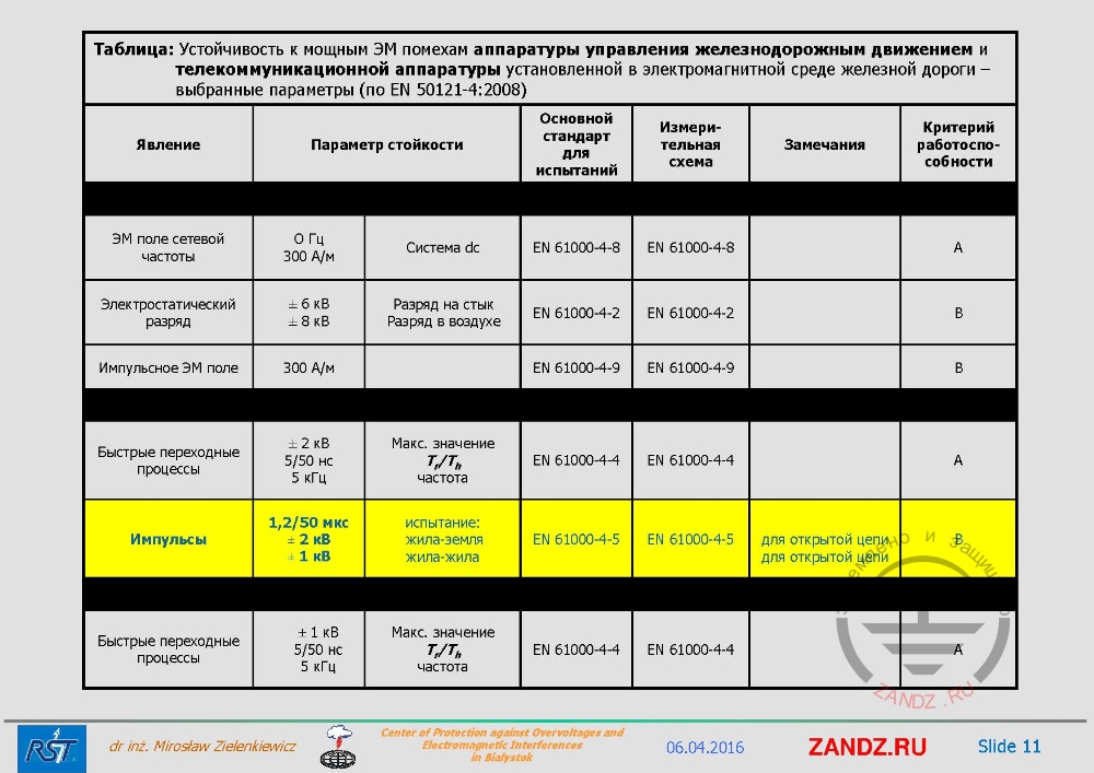
Example for railway devices
| Таблица: Устойчивость к мощным ЭМ помехам аппаратуры управления железнодорожным движением и телекоммуникационной аппаратуры установленной в электромагнитной среде железной дороги – выбранные параметры (по EN 50121-4:2008) | Table: Resistance to powerful electromagnetic interference of railway control equipment and telecommunications equipment installed in the electromagnetic environment of the railway - selected parameters (according to EN 50121-4: 2008) |
| Явление | Effect |
| Параметр стойкости | Parameter for resistance |
| Основной стандарт для испытаний | Basic standard for testing |
| Измерительная схема | Measuring circuit |
| Замечания | Comments |
| Критерий работоспособности | Standard of performance |
| ЭМ поле сетевой частоты | EM field of power supply network frequency |
| Электростатический разряд | Electrostatic discharge |
| Импульсное ЭМ поле | Electromagnetic pulse field |
| Быстрые переходные процессы | Fast transients |
| Импульсы | Pulses |
| Быстрые переходные процессы | Fast transients |
| Система dc | DC network |
| Разряд на стык | Discharge per joint |
| Разряд в воздухе | Air discharge |
| Макс. значение Tr/Th частота | Maximum value of Tr/Th frequency |
|
испытание: жила-земля |
test: core-ground |
| для открытой цепи | for open circuit |
— Here I am showing an example for railway devices, if you look, all of this is specified according to the EN50121-4 2008 standard. And we see that we have the parameters we need here: fields, electrostatics and we will find pulses. Voltage pulse 1.5/50 μs, 2 and 1 kV. Look, the next slide also contains data, and the first line shows stability from the side of the hull. In the second line - the stability of the boards of the output/input from the side of direct and alternating current. And the last one, the third - the stability of the grounding of the object.
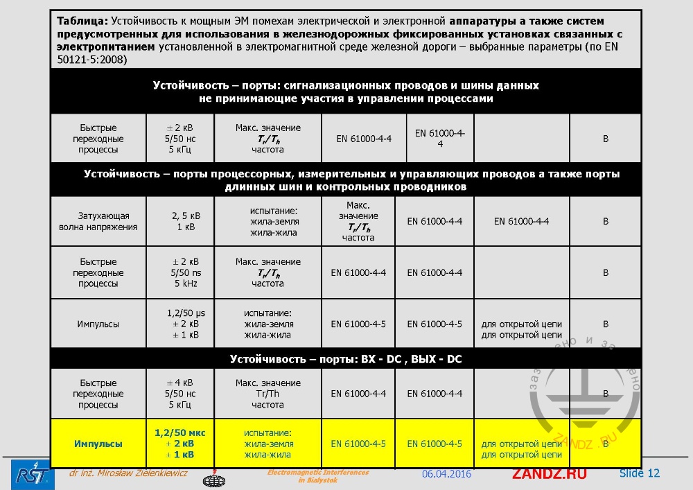
Table of port stability
| Таблица: Устойчивость к мощным ЭМ помехам электрической и электронной аппаратуры а также систем предусмотренных для использования в железнодорожных фиксированных установках связанных с электропитанием установленной в электромагнитной среде железной дороги – выбранные параметры (по EN 50121-5:2008) | Table: Resistance to powerful electromagnetic interference of electrical and electronic equipment as well as systems intended for use in railway fixed installations related to the power supply installed in an electromagnetic environment - choosen parameters (according to EN 50121-5: 2008) |
| Устойчивость – порты: сигнализационных проводов и шины данных не принимающие участия в управлении процессами | Stability - ports: signalling wires and data buses not participating in process control |
| Устойчивость – порты процессорных, измерительных и управляющих проводов а также порты длинных шин и контрольных проводников | Stability - ports of processor, measuring and control wires, as well as ports of long buses and test conductors |
| Устойчивость – порты: ВХ - DC , ВЫХ - DC | Stability - ports: Input - DC, Output - DC |
| Затухающая волна напряжения | Voltage damped wave |
— If we take a look at the following table, here we see the stability of the signalling wires ports and the data bus that are involved in the process control. Stability ports of processors and measuring and control wires, as well as ports of long buses and test conductors. And port stability, DC input. But if we look here, we will not see too much data. Basically, what we can take from here when selecting is the magnitude and voltage pulse with which our devices were tested when they were allowed to work in railway systems in this case. We see, that there are 2 and 1 kV. Question: who thought up the voltage and why exactly 2 or 1 kV?
— See slide 11. 2 kV - core-ground, and 1 kV - core-core. But here you just have to realize that we can't set too high requirements to the manufacturer, because devices will become very expensive. And in this case these standards, these tables do not consider cases when a lightning strikes an object. In these standards it is always written openly, mainly in the introduction to this standard. This means that this equipment must work inside the object in some second zone without interference, but it is stable against such interference for which we tested it here. This does not mean in any way that this equipment will work properly without failure, without interfering, when lightning strikes the object or close to it.
— See slide 12. But these tables, this data gives us important information that we have determined the minimum level of resistance. So, if you think about the table, let's return to it again, we should limit overvoltages in this case at least up to level of 1.2/50 µs pulse, our overvoltages should not be more than 2 or 1 kV. But in reality, if the rated voltage of low-current lines is about 12-48 V, we always try to limit the voltage close to these values in order to reduce the energy that leaks inside the object. Therefore, in this case, the voltage will be much lower if we design right, than the pulses indicated here for the stability of our object.
Stage 2. Master data definition characterizing the rated operating conditions of the protected device
— The next step in the selection of overvoltage protection of low-current systems is to define the master data that characterize the rated operating conditions of the protected device. That is why we know which parameters should not change, and there are quite a lot of them.
Next page >>
slides from 14 to 26
Useful materials for designers:
- Webinars with leading industry experts
- Everything for calculations of grounding and lightning protection
- Useful materials: articles, recommendations, examples
Related Articles:
