Task:
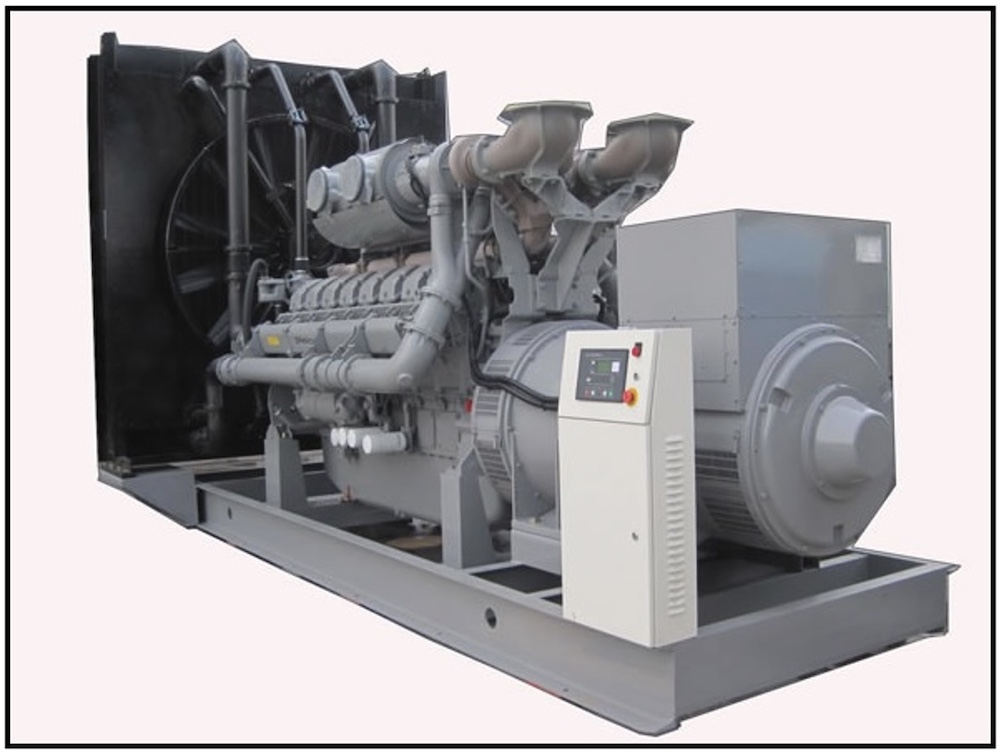
Facility: Diesel-generator set (DGS), dimensions: 6 x 2.4 m.
Soil is clay loam
Soil resistivity: 100 Ohm*m.
Grounding arrangement (GA) is necessary to do with a resistance of not exceeding 4 Ohms.
List of required materials:
Solution:
- The technical solutions adopted in design documents comply with the requirements of environmental protection, sanitary and hygienic, fire safety as well as other standards effective in the territory of the Russian Federation and provide operation of the facility in a way safe for lives and health of the people, while complying with the events provided for by design drawings. Design documentation complies with the requirements of the effective regulatory documents.
- This article considers a solution for grounding of a DGS located in the Moscow Region.
- According to the EIC Rev. 7, item 1.7.101. Resistance of the grounding arrangement to which generator and transformer neutral wires or a single-phase current source outputs are connected, in any time of year, should not exceed 4 Ohms, respectively, with linear voltages 380 V for a three-phase current source, or 220 V for a single-phase current source. The resistance should be provided taking into account natural grounding arrangements as well as grounding electrodes of repeated grounding arrangements for high-voltage PEN or PE wire up to 1 kV with at least two branch lines.
- 3-m copper-plated steel electrodes, 9 pieces are used as a vertical grounding arrangement (copper coating thickness is at least 0.25 mm).
- The copper-plated steel strip with a cross-section of 30x4 mm, combining all vertical electrodes is used as a horizontal ground electrode. The distance to the facility foundation is at least 1 m. Bar deepening is 0.5 to 0.7 m.
- Materials and cross-sections of all wires used in the design comply with the requirements of GOST R 50571.5.54-2013 and the EIC Rev. 7, including new information introduced by Technical Circulation No. 11 of October 10, 2006.
- A grounding arrangement is connected to the internal grounding circuit of the facility at least in two points.
- According to EIC-7 issue, par.1.7.55, Grounding devices for protective grounding of electrical installations for buildings and structures and the 2nd and 3rd categories lightning protection of these buildings and structures, as a rule, shall be common.
- If there are reinforced concrete structures, they should be connected to the grounding device.
- Connection to the grounding arrangement is made through clamps ZZ-005-064.
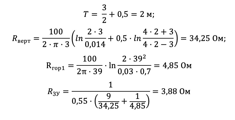
Ground terminal resistance calculation:
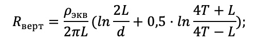
Vertical electrode resistance:
Верт - Vert
Экв - Eq
where ρeq – is soil resistivity, Ohm · m;
L – is vertical electrode length, m;
d – is vertical electrode diameter, m;
T– is depth, i.e. the distance from the ground surface to the ground electrode, m;
Horizontal electrode resistance:

Гор - Hor
where ρ is soil resistivity, Ohm · m;
b is horizontal electrode width, m;
h is horizontal conductor depth, m;
Lгор is horizontal electrode length, m.
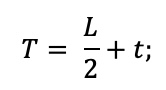
where t is electrode top depth, m
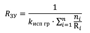
Electrical impedance of the grounding arrangement:
ЗУ - GA
Исп гр - Util
where n is number of sets;
kutil is utilization coefficient;
Верт - Vert
Ом - Ohm
The calculated resistance of the grounding arrangement is 3,88 Ohm, which is less than the required value of 4 Ohm.
List of required materials:
| Item # | Fig. | Part number | Product | Quantity, pcs. |
| 1. |
|
ZZ-001-065 | ZANDZ Copper-plated threaded grounding rod (D14; 1.5 m) | 18 |
| 2. |
|
ZZ-002-061 | ZANDZ Threaded coupling | 10 |
| 3. |
|
ZZ-003-061 | ZANDZ Termination | 9 |
| 4. |
|
ZZ-004-060 | ZANDZ Guide head for jackhammer attachment | 4 |
| 5. |
|
ZZ-006-000 | ZANDZ Conductive grease | 1 |
| 6. |
|
ZZ-008-000 | ZANDZ Attachment to the hammer (SDS max) | 1 |
| 7. |
|
ZZ-005-064 | ZANDZ Conductor connection terminal (up to 40 mm) | 11 |
| 8. |
|
ZZ-007-030 | ZANDZ Waterproofing tape | 4 |
| 9. |
|
GL-11075-50 | GALMAR Copper-plated strip (30 * 4 mm / S 120 mm²; 50-meter strip bundle) | 1 |


Related Articles:
 Lighter for exothermic welding
 Typical Design "Lightning Protection and Grounding for a School"