Task:
Facility: a school;
Facility location: Moscow Region;
Roof material: metal tiles and PVC membrane;
Facade material: gas-concrete blocks, plaster;
Soil: clay loam;
Soil resistivity: 100 Ohm*m.
It is required to perform lightning protection and grounding for the facility.
Solution:
- The technical solutions adopted in design documents comply with the requirements of environmental protection, sanitary and hygienic, fire safety as well as other standards effective in the territory of the Russian Federation and provide operation of the facility in a way safe for lives and health of the people, while complying with the events provided for by design drawings. Design documentation complies with the requirements of the effective regulatory documents.
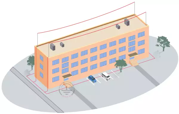
- This section considers a solution for an external lightning protection system for a school located in: Moscow Region.
- The school is classified as "conventional" in terms of INSTRUCTIONS FOR LIGHTNING PROTECTION OF BUILDINGS, STRUCTURES, AND INDUSTRIAL UTILITIES SO 153-34.21.122-2003 and as Category III in terms of INSTRUCTIONS FOR ARRANGEMENT OF LIGHTNING PROTECTION FOR BUILDINGS AND STRUCTURES RD 34.21.122-87. The required lightning protection system should not be less than 0.9.
- According to SO 153-34.21.122-87, item 3.3.1. In general, the lightning arresters should be chosen using the respective software capable of calculating the protection zones or the probability of the lightning strike into the facility (or a group of facilities) of any configuration, with the random position of almost any lightning arrester.
- In addition to SO 153-34.21.122-2003, RECOMMENDATIONS FOR OPERATIONAL AND TECHNICAL DOCUMENTATION, PROCEDURE FOR ACCEPTING FOR OPERATION AND OPERATION OF LIGHTNING PROTECTION DEVICES state: When checking the protection reliability using a software, data of computer calculations are provided as a summary of design variants and a resolution on their efficiency is formed.
- Calculations of reliability for a lightning protection system are performed according to Technical Circulation No. 25/2009 of the ROSELECTROMONTAZH Association ON USING SPECIAL SOFTWARE TO CALCULATE THE EFFICIENCY OF PROTECTIVE EFFECTS OF LIGHTNING ARRESTERS stating: When designing systems of external lightning protection of facilities, it is recommended to use the following: to provide optimal generation of protection zones of the buildings and structures with complex forms having roofs of different heights, protruding needles, towers, variable geometry, buildings higher than 150 m, building complexes and other complex facilities, one should use the respective software products, e.g. "Software for calculating rod and wire lightning arresters using a statistical method" developed by OAO ENIN.
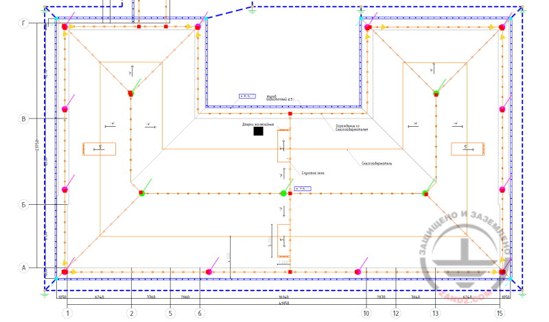
- The lightning protection for a facility is made using 5 x 2 m lightning rods ZZ-201-002-16 located on the roof ridges, 12 x 1.5 m lightning rods GL-21134 located on fencing, and 4 x 2 m lightning rods on a concrete foundation GL-21131 located on a flat roof.
- According to the EIC, item 1.7.103, total dissipation resistance of grounding electrodes (including natural ones) of all repeated groundings of the PEN wire in each high-voltage line in any season of the year should not be more than 10 Ohm, respectively, with linear voltages 380 V in a three-phase line.
- The design of the grounding arrangements for the facilities conforms to the requirements of RD 34.21.122-87, item 2.26.
- Materials and cross-sections of all wires used in the design comply with the requirements of GOST R 50571.5.54-2013 and the EIC Rev. 7, including new information introduced by Technical Circulation No. 11 of October 10, 2006.
- A copper-plated steel wire (copper coating thickness of at least 70 μm), d8 mm (GL 11149), is used as a current collector.
- Current collectors are installed using holder ZZ-202-015 on a flat roof, GL-11564A on the ridge, GL-11747A on roof slopes, GL-11514N on a fencing, and GL-11703A on vertical surfaces. The accepted pitch of terminals is 0.8-1.0 m.
- All metal elements located on the roof must be connected to the main conductor cable with the terminals GL-11545. Stairs, railings, are attached using the terminal-clamp GL-11514N.
- The universal GL 11551A clamp is used to connect the rolled products over the length and in assemblies.
- Downdrops are made along the walls where they are connected to the horizontal grounding arrangement at the level of 0.5 m from soil.
- Current collector is connected to the grounding bar using clamp GL-11562A.
- The grounding arrangement is made according to RD 34.21.122-87, item 2.26.
- Vertical copper-plated steel electrodes 3 m long are used as grounding devices at the downdrops of the down conductors.
- The copper-plated steel strip with a cross-section of 30x4 mm, combining all vertical electrodes is used as a horizontal ground electrode. The distance to the facility foundation is at least 1 m. Strip deepening is 0.5 to 0.7 m.
- According to RD, item 1.8, artificial grounding arrangements should be located under the asphalt coating or in a rarely populated areas (on lawns, at the distance of 5 m or more from soil roads and pavements, etc.).
- According to EIC-7 issue, par.1.7.55, Grounding devices for protective grounding of electrical installations for buildings and structures and the 2nd and 3rd categories lightning protection of these buildings and structures, as a rule, shall be common.
- If there are concrete-steel constructions, they shall be connected to down conductors/grounding device.
- Estimated resistance of the grounding arrangement is 1.33 Ohm.
- Results of the calculations performed by using the software developed by OAO G.M. Krzhizhanovskiy Energy Institute (OAO ENIN):
the density of lighting discharges into the ground is 4 strikes/sq. km per year;
the total number of strikes into the system is 0.099 (once every 10 years);
the total number of breakthroughs (the strikes directly into the facility bypassing lightning arresters) is 0.010 (once every 100 years).
System reliability is 0.9. - The protocol generated based on the results of calculation of reliabilities of a lightning protection system is provided in Appendix 1 to the design.
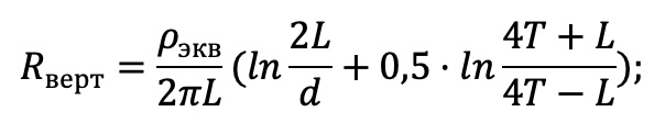
Ground terminal resistance calculation:
Vertical electrode resistance:
Верт - Vert
Экв - Eq
where ρEq is soil resistivity, Ohm · m;
L is vertical electrode length, m;
d is vertical electrode diameter, m;
T is depth, i.e. the distance from the ground surface to the ground electrode, m;
Horizontal electrode resistance:
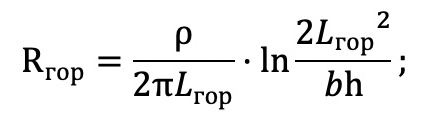
Гор - Hor
where ρ is soil resistivity, Ohm · m;
b is horizontal electrode width, m;
h is horizontal conductor depth, m;
LHor is horizontal electrode length, m.
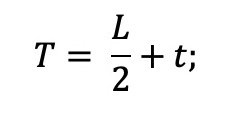
where t is electrode top depth, m
Electrical impedance of the grounding arrangement:
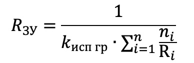
where n is number of sets;
kисп is utilization coefficient;
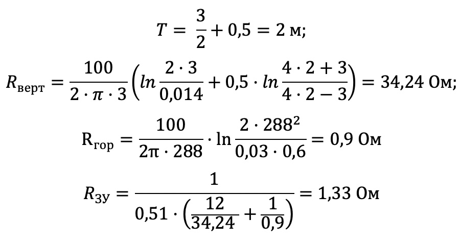
The calculated resistance of the grounding arrangement is 1,33 Ohm, which is less than the required value 10 Ohm.
List of required materials:
| Position | Designation | Description | Quant. |
| 1. | ZZ-201-002-16 | ZANDZ Lightning arrester 2 meters high for installation in threaded holders (M16; stainless steel) | 5 |
| 2. | ZZ-203-003 | ZANDZ Ridge holder for a lightning arrester (thread M16; current collector connection d8-10mm; stainless steel) | 5 |
| 3. | GL-21134 | GALMAR Interception rod tower (1.5 meters; for vertical surfaces; galvanized steel) | 12 |
| 4. | GL-21131 | GALMAR Lightning rod (2.0 m; on a single concrete foundation; zinc-plated steel) | 4 |
| 5. | GL-11149-50 | GALMAR Copper-plated wire (D 8 mm/S 50 mm²; 50-meter bundle) | 16 |
| 6. | GL-11551A | GALMAR Conductor connection clamp (painted zinc-plated steel) | 80 |
| 7. | ZZ-202-015 | ZANDZ ZZ-202-015 Fastener for a circular conductor on a flat roof (D 8 mm; plastic + concrete) | 200 |
| 8. | GL-11564A | GALMAR Conductor crest clamp providing 15mm elevation of the conductor over the clamp (painted galvanized steel) | 60 |
| 9. | GL-11747A | GALMAR Conductor roof clamp for the roof coated with metal shape / corrugated sheeting (painted galvanized steel) | 80 |
| 10. | GL-11703A | GALMAR Terminal for fastening the main conductor cable with elevation (15 mm height; painted zinc-plated steel) to the facade/wall | 290 |
| 11. | GL-11514N | GALMAR Terminal for fastening the main conductor to a drain pipe (tinned copper strip + stainless steel terminal) | 190 |
| 12. | GL-11545A | GALMAR Main conductor rain water gutter terminal (painted zinc-plated steel) | 30 |
| 13. | GL-11562A | GALMAR Control terminal wire + strip (painted galvanized steel) for main conductors connection | 12 |
| 14. | GL-11075-50 | GALMAR Copper-plated strip (30 * 4 mm / S 120 mm²; 50-meter strip bundle) | 7 |
| 15. | GL-11075-10 | GALMAR Copper-clad strip (30x4 mm/S 120 mm²; 10-meter strip bundle) | 1 |
| 16. | ZZ-001-065 | ZANDZ Copper-plated threaded grounding rod (D14; 1.5 m) | 24 |
| 17. | ZZ-002-061 | ZANDZ Threaded coupling | 13 |
| 18. | ZZ-003-061 | ZANDZ Termination | 12 |
| 19. | ZZ-004-060 | ZANDZ Guide head for jackhammer attachment | 5 |
| 20. | ZZ-005-064 | ZANDZ Conductor connection terminal (up to 40 mm) | 19 |
| 21. | ZZ-006-000 | ZANDZ Conductive grease | 2 |
| 22. | ZZ-007-030 | ZANDZ Waterproofing tape | 5 |
| 23. | ZZ-008-000 | ZANDZ Attachment to the hammer (SDS max) | 1 |
Attachment: Project in DWG and PDF formats
 |
DWG and PDF files are available for download only to authorized users.
Related Articles: