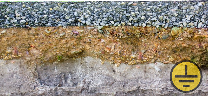
The resistivity of the soil is the main parameter that affects the design of the grounding device: the number and length of grounding electrodes. Physically, it equals the electrical resistance that the soil exerts on the current when it passes the distance between the opposite faces of a 1-cubic-meter conventional cube. M; Dimension Ohm * m. The specific resistance depends on many factors: the composition and structure of the soil, its density, humidity, temperature, the presence of impurities - salts, acids, alkalis. All these parameters change throughout the year, so the resistance of the soil changes accordingly. This fact should be taken into account when making measurements, calculations, and also when measuring the resistance to spreading of an installed grounding device.
Soil resistance and grounding resistance
The lower is the resistivity of soil, the better the electric current flows in the medium, and the less resistance of the grounding device is obtained. Low ground resistance provides ground absorption of damages, leakage currents and lightning currents, which prevents their undesirable leakage through the conductive parts of electrical installations and protects people in contact with them from electric shock, and equipment - from interference and disturbances. A grounding device must necessarily be supplemented by a properly organized A system of potential equalization.
Such facilities as a residential building and power line do not require such low ground resistance, such as substations and facilities with a large volume of information and communication equipment: data centers, medical centers and communication facilities. A lower resistance of the grounding device can be achieved by current spreading from a larger number of electrodes, while the high soil resistance leads to an even larger increase of the ground electrode sizes.
The resistance rate of the grounding device is determined by EIC 7 ed. section 1.7. - for electrical installations of different voltage classes, items 2.5.116-2.5.134 for power transmission lines, as well as other industry standards and documentation for apparatuses and devices.
The specific resistance is mainly dependent on the type of soil. So, "good" soils with low resistance are clay, black soil (80 ohm * m), clay loam (100 ohm * m). The resistance of sand is highly dependent on the moisture content and ranges from 10 to 4000 Ohm * m. In stony soils, it can easily reach several thousand Ohm * m: for chipped rocks - 3000-5000 Ohm * m, and for granite and other rocks - 20,000 ohm * m.
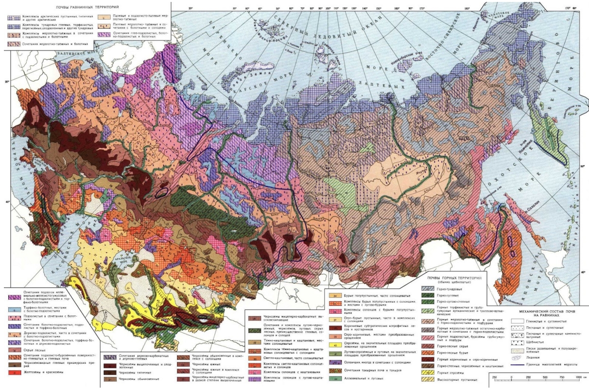
Specific resistance of soils in Russia
The average specific resistivity of soils frequently found on the territory of Russia is given in the table on the page devoted to Resistivity of soil.
You can learn the type of soil on the map of soils on the territory of Russia (to view the map in full size, click on it).
The values given in the tables are for reference only and are only suitable for an approximate calculation in case that no other information is available. In order to obtain an accurate value of the resistivity, it is necessary to carry out research works. Ground measurements are carried out in the field conditions by the ammeter-voltmeter method, and also by measuring the engineering-geological elements (EGE), carried out at different depths by the method of vertical electric sounding (VES). The values obtained by these two methods can significantly differ, as well as the characteristics of the soil of slightly remote points on the terrain. Therefore, in order to exclude an error in the calculations, it is necessary to take the maximum of the results of these two methods when bringing to a single-layer computational model. If it is necessary to bring the soil to a two-layer model for the caltulations, then only the VES method can be used.
Seasonal change in soil resistance and its registration
To consider seasonal changes and the effects of natural phenomena, the "Guidelines for the design, construction and operation of grounding in wireline and radio transmission units" operates with the freezing coefficient, which is prescribed for a certain climatic zone of Russia and the moisture coefficient, taking into account the moisture accumulated by the ground and the amount of precipitation that fell before the measurement. AD 153-34.0-20.525-00 when determining the resistance of the grounding device of substations, the seasonal coefficient is used.
When the soil is impregnated with water, the resistivity can decrease tens of times, and at freezing it can increase severalfold. Therefore, depending on the time of the measurement, it is necessary to take into account these coefficients.
This will help to prevent exceeding the norm of the grounding device as a result of changes in the resistivity; the normalized value in accordance with the EIC 7 ed. should be provided under the most unfavorable conditions at any time of the year.
With the increase in the dimensions of the grounding device, the effect of seasonal changes is significantly reduced. If the ground electrode has horizontal dimensions of about 10 meters, then its resistance during the year can vary by tens and hundreds of times, whereas the resistance of the ground electrode with the dimensions of 100-200 meters varies only twice. This is due to the fact that the current spreading depth is commensurate with the dimensions of the horizontal ground electrode. Thus, the horizontally distributed design affects deep soil layers, often with low resistivity at any time of the year.
"Complex soils" with high specific resistivity
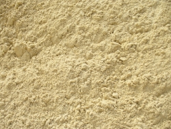
dry sand

Limestone
Some types of soil have an extremely high resistivity. Its value for rocky soils reaches several thousand Ohm * m, while the organization of a grounding device in such an environment is associated with a number of difficulties - significant material costs and volumes of ground works. Due to solid inclusions, it is practically impossible to use vertical electrodes without drilling. An example of grounding in rocky ground conditions is given on the page.
Perhaps, an even more complicated case is a permafrost soil. As the temperature decreases, the resistivity increases sharply. For loam at +10 C° , it is about 100 Ohm * m, but at -10 C°, it can reach 500 - 1000 Ohm * m. The depth of freezing of the permafrost soil varies from a few hundred meters to several kilometers, while in summer time only the upper layer of insignificant thickness thaws: 1-3 m. As a result, the whole zone of effective current spreading throughout the year will have a significant resistivity - about 20,000 Ω * m in permafrost loam and 50000 Om * m in permafrost sand. This is fraught with the organization of a grounding device on a huge area, or by the use of special solutions, for example, electrolytic grounding. For a visual comparison, after clicking on the link, you can see the calculation in the permafrost.
Decisions to achieve the necessary resistance
Traditional methods
In good soils, as a rule, a traditional grounding device consisting of horizontal and vertical electrodes is installed.
The use of vertical electrodes has an important advantage. With the increase of depth, soil resistivity "stabilizes". In deep layers, it is less dependent on seasonal changes, and, due to the increased moisture content, has a lower resistance. This feature very often allows you to significantly reduce the resistance of the grounding device.
Horizontal electrodes are used to connect vertical, they also contribute to an even greater reduction in resistance. But they can also be used as a stand-alone solution when mounting of vertical pins is difficult, or when it is necessary to create a grounding device of a certain type, for example, a mesh.
Non-standard ways
In hard stony and permafrost soils, the installation of traditional grounding is associated with a number of problems, ranging from the complexity of installation due to the specifics of the terrain, ending with the huge dimensions of the grounding device (correspondingly - large volumes of construction works) necessary to match its resistance to the norms.
In the conditions of the permafrost soil, there is also such a phenomenon as ejection, as a result of which the horizontal electrodes appear above the surface in a year.
To solve these problems, specialists often resort to the following measures:
- Replacement of the required volumes to the ground with a low specific resistivity (has limited benefit in case of permafrost soil, since the replacement soil also freezes). The volumes of such soil are often very large, and do not always lead to the expected results, because the area of the ground electrode operation in depth is almost equal to its horizontal dimensions, so the influence of the upper layer can be negligible.
- Organization of a remote ground electrode with low resistivity, which allows you to install a ground electrode at the distance of up to 2 km.
- The use of special chemicals - salts and electrolytes, which reduce the resistivity of the frozen ground. This activity should be conducted every few years because of the process of leaching.
One of the most preferred solutions in difficult conditions is electrolytic grounding, it combines the chemical effect on the soil (reducing its resistivity) and the replacement of soil (reducing the effect of freezing). Electrolytic electrode is filled with a mixture of mineral salts, which are evenly distributed in the working area and reduce its specific resistance. This process is stabilized with a near-electrode filler, which makes the leaching process of the salts uniform. The use of electrolytic grounding helps to avoid the problems of organizing a traditional grounding device, significantly reduces the amount of equipment, the size of the ground electrode and the volumes of excavation.
Conclusion
When designing a grounding device, it is necessary to have reliable data on the resistivity of soil at the construction site. Accurate information can be obtained only through surveys and measurements on the ground, but for various reasons it happens so that there is no possibility to carry them out. In this case, you can use the reference charts, but you should take into account that the calculation will be indicative.
Regardless of how the resistivity values are obtained, all influencing factors must be carefully considered. It is important to consider the limits in which the resistivity can vary so that the resistance of the grounding device never exceeds the norm.
See also:
- Example calculation: how to make ground in the permafrost?
- The article from Professor E. M. BazelyanGrounding in lightning protection"
- What is a disspation array device and how it works?
- Useful materials for designers: articles, recommendations, examples
- Soil resistivity table
Related Articles:
 Why Cannot Vertical Earthing Devices Be Installed Close to Each Other?
 Electrolytic Grounding in Permafrost Soils: Should Vertical of Horizontal Electrodes Be Used?