This question has concerned experts for a long time. Taking into account that soil resistance increases as the temperature lowers, it is necessary to find a way to solve this problem. Grounding using standard vertical metal electrodes may be inefficient, as an increased number of such grounding electrodes will cause an increase of material and work costs. So how should this problem be solved?

There two main methods for installing grounding in permafrost:
- Soil replacement around the electrode. The soil is usually replaced with graphite and clay-based material (materials with sufficiently high electric conduction). The disadvantage of this method is the high price, but in some cases it cannot even be used.
- Another well-known way to decrease resistivity is salinizing the soil. The essence of this solution is filling the space around the electrode with mineral salts. An intricacy of this method is due to the natural phenomenon that the salt is washed away, which decreases the efficiency of grounding. A chemical reaction between the grounding electrodes and salt usually leads to metal corrosion as well.
So which way should be chosen? It is suggested to consider a completely different modern way that is used for grounding in complex permafrost and rocky conditions - electrolytic grounding. A hollow electrode with a perforation in its horizontal part that is filled with mineral salt is placed at a depth of 0.7 meters in an area where the permafrost has melted. This mix absorbs water from the environment and turns into an electrolyte;
as it passes deeper into the soil, it increases its electrical conductivity and decreases resistivity, as well as reducing frost penetration.
This type of grounding is used in soil with high resistivity of 300-500 ohms/meter. In this way, grounding can be installed without resorting to the special technique of filling the soil. It can also be fitted at facilities where it is impossible to install grounding electrodes at a depth of at least 1 meter.
Let's look at the example of calculating the resistance for a grounding device in permafrost!
Solution: In accordance with rev. 7 of. a set of measures is implemented. Calculation of a grounding device with resistance of 10 ohms or lower as requested by the customer. The soil in the location for grounding device installation is permafrost, mostly clay loam, with a resistivity of 1,500 ohms/meter.
There are two versions of the set of measures to ensure compliance with the necessary requirements for a grounding device:
Option 1. Electrolytic grounding.
In order to ensure the specified resistance of the grounding device electrolytic grounding ZANDZ ZZ-100-102, specially designed for use in permafrost and rocky soil, is recommended.
- Six kits for electrolytic grounding ZANDZ ZZ‑100‑102 are installed. The kits are installed in parallel at a distance of 7 meters for an acceptable efficiency ratio and optimal electrolyte distribution in the soil.
- The electrolytic kits are connected by a horizontal electrode made of copper-bonded stainless steel tape with a cross-section of 4x30 mm at a depth of 0.5 m.
- A horizontal electrode of 5 m in length is laid up to the wall of the building.
- As an oval-shaped talik zone 3x6 meters in size is formed, the electrodes must be placed at an appropriate distance from the foundations of buildings and other engineering structures.
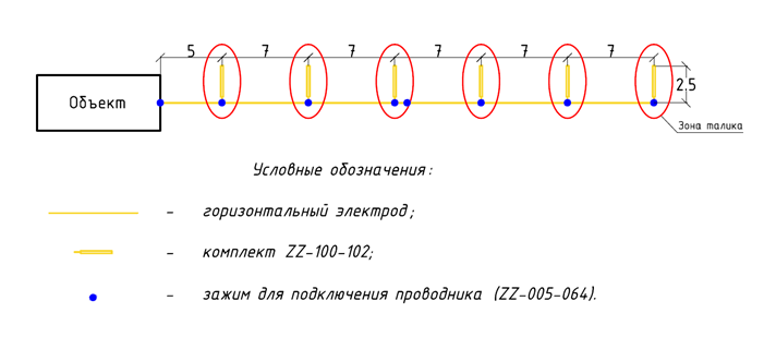
Figure 1. Grounding device elements layout
Resistance calculation for the grounding device:
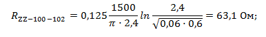
1). Resistance of ZZ-100-102 kit:
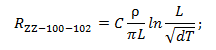
where C is a non-dimensional coefficient describing the electrolyte content of the surrounding soil;
L is the length of the grounding electrode in meters;
d is the grounding electrode diameter in meters;
T is the depth - the distance from the ground surface to the grounding electrode in meters;
ρ – soil resistivity in ohms/meter.
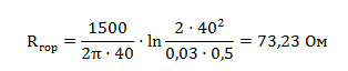
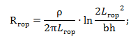
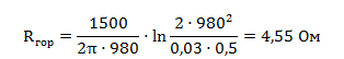
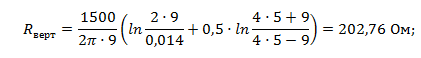
2). Resistance of the horizontal electrode:
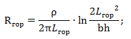
where ρ is the soil resistivity in ohms/meter;
b is the horizontal electrode width in meters;
h is the depth of the horizontal mesh in meters;
Lгор is the length of the horizontal electrode, in meters;
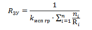
3).Impedance of the grounding device::
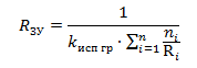
where n is the number of kits;
kисп is the use factor;
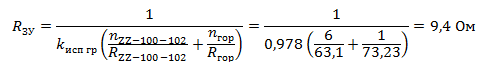
The design resistance of the grounding device is 9.4 ohms.
List of necessary equipment:
| № | Fig. | Product item |
Product
|
Q-ty |
|
1. |
 |
ZZ-100-102 | ZANDZ Electrolytic grounding kit (horizontal; 3 m) | 6 |
| 2. |  |
GL-11075-20 | GALMAR copper-plated tape (30 * 4 mm / S 120 mm²; coil of 20 meters) | 2 |
| 3. |  |
ZZ-005-064 |
ZaNDZ Clamp for connecting conductors (up to 40 mm) |
8 |
| 4. |  |
ZZ-007-030 | Option 2. Modular grounding | 3 |
Option 2. Modular grounding
- A horizontal mesh with the dimensions 60x70 m and pitch of 10 m is made. The mesh is made of copper-bonded stainless steel tape with a cross-section 4x30 mm and is laid at a depth of 0.5 m.
- 56 vertical electrodes of 14 mm in diameter and 9 m in length are installed in the nodes of the horizontal mesh
- A horizontal electrode 10 m long is laid up to the wall of the building.
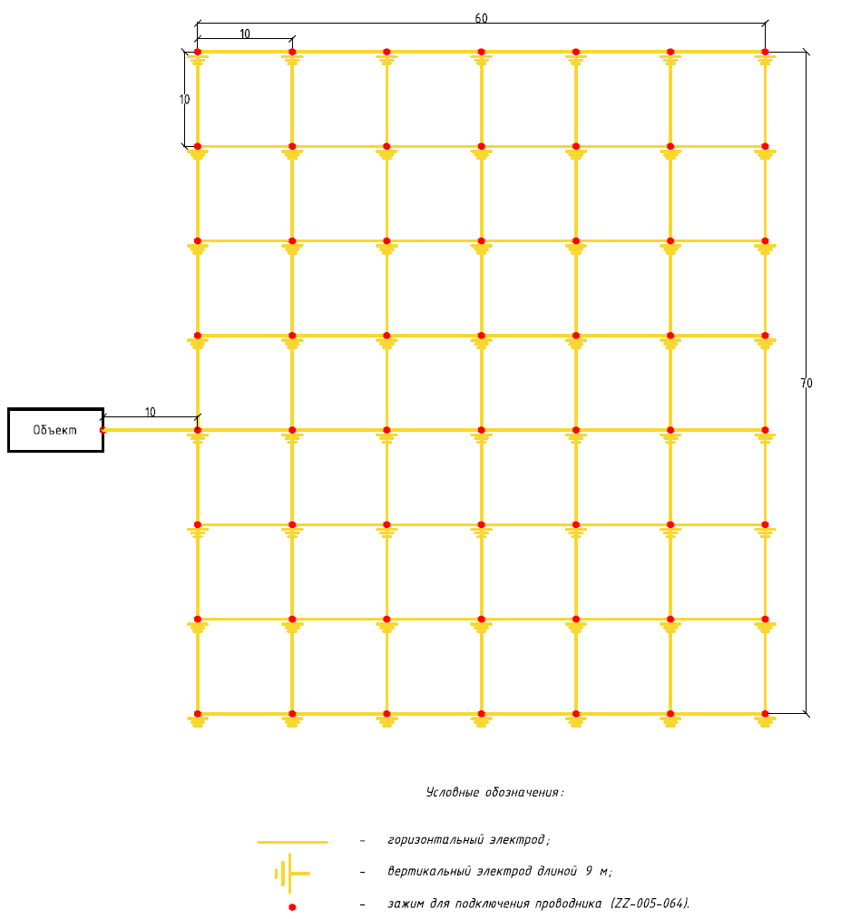
Figure 2. Grounding device elements layout
Resistance calculation for the grounding device:
1). Resistance of the horizontal electrode:
where ρ is the soil resistivity in ohms/meter;
b is the horizontal electrode width in meters;
h is the depth of the horizontal mesh in meters;
Lгор is the length of the horizontal electrode, in meters;
2). Resistance of the vertical electrode:
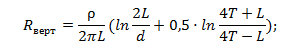
where ρ is the soil resistivity in ohms/meter;
L is the length of the vertical electrode in meters;
d is the diameter of the vertical electrode in meters;
T is the depth - the distance from the ground surface to the grounding electrode in meters;

where t is the depth of the top of the electrode, m
3). Impedance of the grounding device:
where n is the number of kits;
kисп is the use factor;
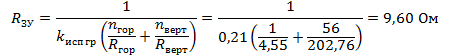
The design resistance of the grounding device is 9.60 ohms.
List of necessary equipment:
|
№
|
Fig. | Product item | Product | Q-ty |
| 1. | |
GL-11075-50 | GALMAR Copper-plated tape (30 * 4 mm / S 120 mm²; coil 50 meters) | 19 |
| 2. | |
GL-11075-20 | GALMAR Copper-bonded tape (30*4 mm / S 120 mm²; coil 20 meters) | 1 |
| 3. | |
GL-11075-10 | GALMAR Copper-plated tape (30 * 4 mm / S 120 mm²; coil of 10 meters) | 1 |
| 4. |  |
ZZ-005-064 | 57 | |
| 5. |  |
ZZ-001-065 | ZANDZ Copper-plated screw grounding pin (D14; 1.5 m) | 336 |
| 6. |  |
ZZ-002-061 | ZANDZ threaded connecting coupling | 281 |
| 7. |  |
ZZ-003-061 | ZANDZ Starting tip | 56 |
| 8. |  |
ZZ-004-060 | ZANDZ Driving head for a breaker hammer | 68 |
| 9. |  |
ZZ-008-000 | ZANDZ Head for a breaker hammer (SDS max) | 1 |
| 10. | .jpg) |
ZZ-006-000 | ZANDZ Conductive grease | 29 |
| 11. |  |
ZZ-007-030 | ZANDZ Waterproof tape | 19 |
Taking into account all costs for materials and works, we have come to the conclusion that electrolytic grounding is more efficient. The costs for electrolytic grounding are 2.5 times lower than for a modular system.
All the details about electrolytic grounding are here! Do you have any questions left? Please contact our Technical Center ZANDZ.com