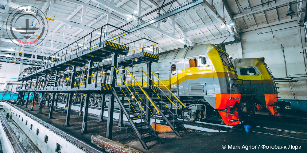
Lightning protection is an essential part of the safety system for power supply facilities. The train deport being an important part of the vehicle lifecycle is not an exception.
The lightning may cause serious loss by damaging infrastructure and equipment as well as creating hazards for the personnel. The lightning protection system protects against lightning discharges by directing them to the grounding system bypassing the train depot structures. An integrated approach to lightning protection designing provides safety and continuity of railroad facilities operations.
The ZANDZ Technical Center has received the following task: to develop detailed design for the lightning protection system for the train depot using lightning wire as a lightning arrester and considering that no equipment is installed on the roof. We are happy to share our experience of developing detailed design for the lightning protection of the train depot that can be used when necessary.
General data:
Lightning protection and grounding of the train depot are made in accordance with:
ELECTRICAL INSTALLATIONS CODE (EIC), Rev. 7, hereinafter, EIC-7;
SO 153-34.21.122-2003 "INSTRUCTIONS FOR MOUNTING LIGHTING PROTECTIONS OF BUILDINGS, STRUCTURES AND INDUSTRIAL COMMUNICATIONS", hereinafter referred to as SO;
RD 34.21.122-87 "INSTRUCTIONS FOR MOUNTING LIGHTING PROTECTION OF BUILDINGS AND STRUCTURES", hereinafter referred to as RD.
The facility is classified as Category III in terms of the lightning protection according to RD and to conventional facilities according to SO.
Soil resistivity: 200 Ohm*m.
A set of measures to meet the necessary requirements to the lightning protection and grounding systems for the train depot includes the following solutions:
The facility lightning protection is made using a lightning wire with the step not more than 10 m. The wire is made of steel copper-plated (copper coating thickness of at least 70 mcm) wire, d 8 mm (ZZ-11149).
Steel copper-plated wire, D8 mm (ZZ-11149) (copper coating thickness of at least 70 mcm) is used as a current collector. According to item 2.26 of RD, when the wire or the metal roof is used as lightning arrester along the building perimeter, the external circuit consisting of horizontal electrodes should be laid at the depth of at least 0.5 m. Minimum allowable cross-sections (diameters) of electrodes of artificial grounding electrodes are determined in Table 3, i.e. at least 6 mm in air and at least 10 mm in the ground.
Current collectors are installed using a clamp ZZ-11711 on the roof, and ZZ-11747 on vertical surfaces. The clamp spacing is 0.8 to 1.0 m. According to item 3.2.2.3 of SO, current collectors are installed along the perimeter of the protected facility such that the average distance therebetween would not be less than the values provided in Table 3.3, i.e. 20 meters.
The multi-purpose ZZ-11551A clamp is used to connect the rolled products over the length and in assemblies.
All metal elements located on the roof shall be connected to the сurrent collector using ZZ-11545А clamps.
Copper-plated steel electrodes 3 m long in the locations of the current collector downdrops are used as vertical grounding electrodes. The copper-plated steel strip with a cross-section of 30 x 4 mm (ZZ-11075), combining all vertical electrodes, is used as a horizontal ground electrode. The distance to the facility foundation is at least 1 m. Strip deepening is 0.5 to 0.7 m.
According to EIC-7 issue, par.1.7.55, Grounding devices for protective grounding of electrical installations for buildings and structures and the 2nd and 3rd categories lightning protection of these buildings and structures, as a rule, shall be common.
If there are concrete-steel constructions, they shall be connected to current collectors/grounding device.
Connection to the grounding arrangement is made using ZZ-005-064 clamps.
Grounding terminal resistance calculation:
Vertical electrode resistance:
where ρ is soil resistivity, Ohm*m;
L is vertical electrode length, m;
d is vertical electrode diameter, m;
T is depth, i.e. the distance from the ground surface to the grounding terminal, m.
Horizontal electrode resistance:

where ρ is soil resistivity, Ohm•m;
b is horizontal electrode width, m;
h is horizontal electrode depth, m;
Lhor is horizontal electrode length, m.

where t is depth of the top of the electrode, m.
Electrical impedance of the grounding arrangement:

where n is number of sets;
kutil is utilization ratio.
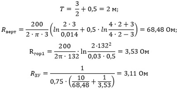
Lower:
Upper:
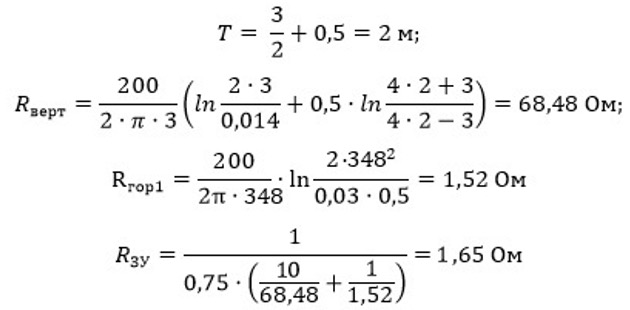
Estimated resistances of grounding devices are 3.11 Ohm and 1.65 Ohm which are less than the allowable resistance of 4 Ohm.
Appendix: design in DWG and PDF formats
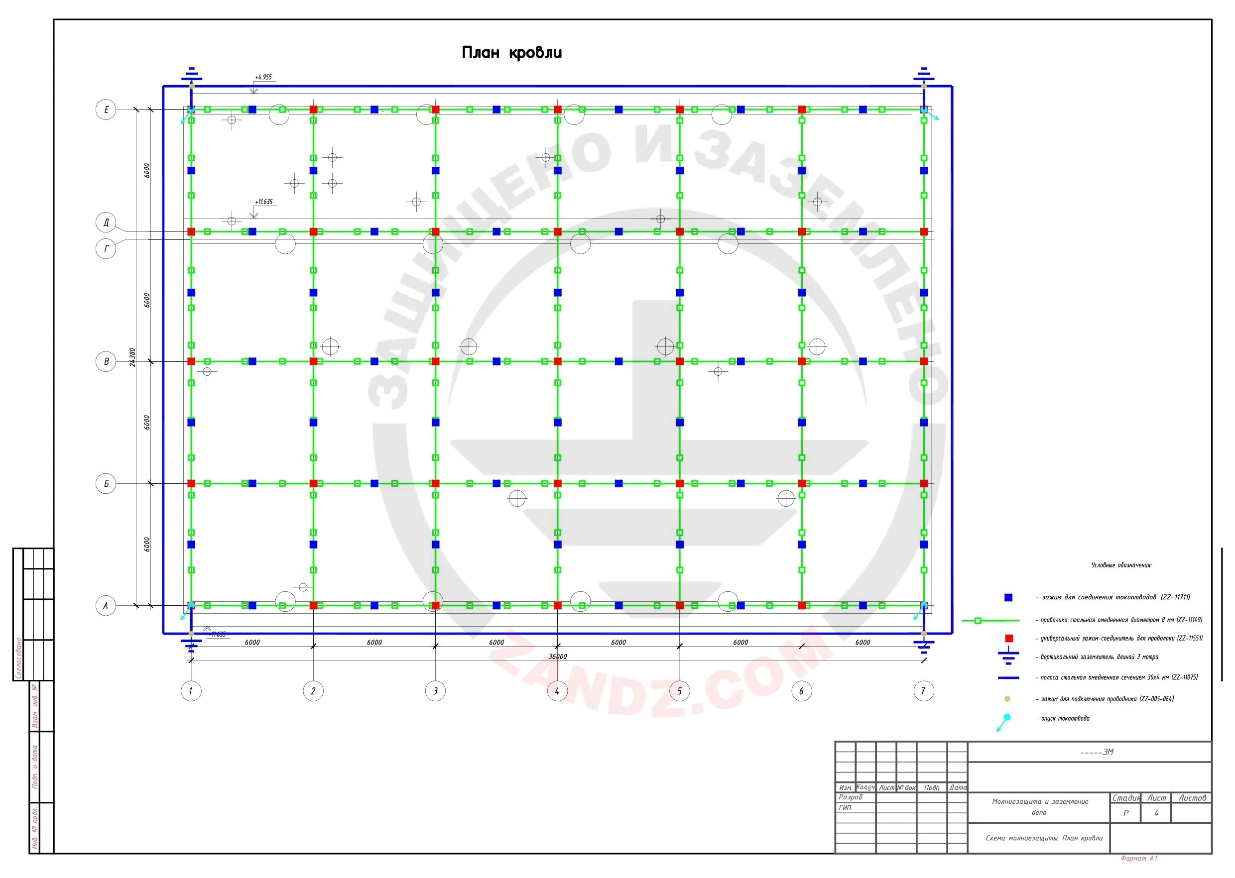
Click here to view the diagram in full.
DWG and PDF files are available for download by the signed-in users only.
Need a design of grounding and lightning protection? Order now by contacting the ZANDZ Technical Center
Related Articles:
.jpeg) Exemplary Design of Grounding System for a Control Station Using Coke Fines
Exemplary Design of Grounding System for a Control Station Using Coke Fines
 Calculation Example for Lightning Protection and Grounding of a Workshop Located in a Gravelly Soil of 3,000 Ohm*m
 Lightning Protection Design for a Railroad Terminal and Station

