Task:
Facility: production shop.
The soil resistivity accepted for calculations is 3,000 Ohm * m.
Load-bearing constructions are made of metal.
Enclosure walls are made of sandwich panels.
The roof is flat.
Solution
The activities were made in accordance with the Electrical Installations Code (EIC), Rev. 7, Chapter 1.7, SO 153-34.21.122-2003 "Guidelines for Arrangement of Lightning Protection of Buildings, Structures, and Industrial Utilities" (hereinafter referred to as SO), and RD 34.21.122-87 "Guidelines for Arrangement of Lightning Protection of Buildings and Structures" (hereinafter referred to as RD).
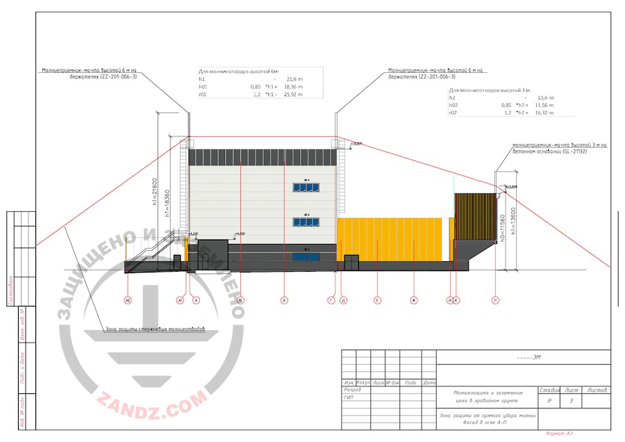
The facility is classified as conventional according to SO. The system's reliability is 0.9. The calculation of lightning rod protection zones is performed as per SO, item 3.3.2.3.
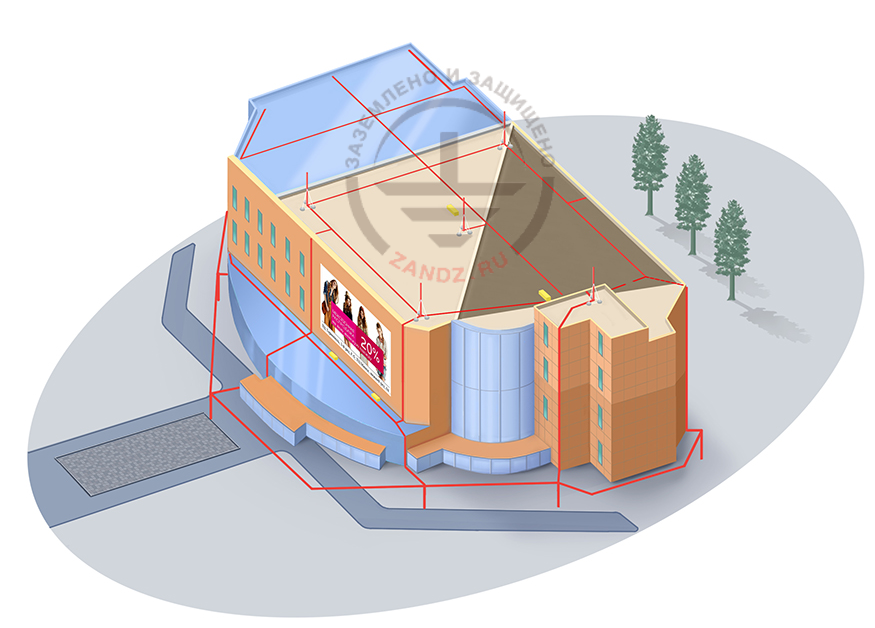
The protection against direct lightning strikes is made using 6 x 6 m lightning masts ZZ-201-006-3 located on wall holders (mountings are spaced at 1 m) and 2 x 3 m lightning masts GL-21132. Lightning rods ZZ-201-006-3 are secured using load-bearing elements of the building frame. Conductors of current collectors are connected to the masts using a D42 mm clamp for lightning rod.
Steel copper-clad wire, D8 mm (GL-11149) (copper coating thickness of at least 70 microns) is used as a current collector.
The installation of current collectors is carried out using the clamp GL-11703A - on vertical surfaces. The clamp spacing is 0.8 to 1.0 m.
All metal elements located on the roof must be connected to the current collector with the clamp GL-11545. Stairs, railings are attached using the terminal-clamp GL-11514N.
A multi-purpose clamp GL-11551A is used to interconnect rolled metal products.
To connect circular conductors of the current collector to the terminal of the grounding arrangement, a connecting clamp GL-11562A is used.
According to the EIC, item 17.103, total dissipation resistance of ground terminals (including natural ones) of all repeated groundings of the PEN wire of each high-voltage line in any season of the year shall not exceed 5, 10 and 20 Ohm, respectively, with linear voltages of 660, 380, and 220 V of a three-phase source or 380, 220, and 127 V of a single-phase source. The dissipation resistance of the ground terminal for each repeated grounding electrode shall not exceed 15, 30, and 60 Ohm, respectively, with the specified voltages. With soil resistivity ρ > 100 Ohm*m, said standards may be increased by 0.01 • ρ times, but not more than by 10 times.
ZZ-100-102 electrolytic grounding sets are used as a grounding arrangement at current collectors downdrops. The copper-plated steel strip with a cross-section of 30 x 4 mm, combining all sets, is used as a horizontal ground terminal. The distance from the electrodes to communications and foundations shall be no less than 3 m. The deepening is 0.6 m.
According to RD, item 1.8, artificial ground terminals shall be located under the asphalt coating or in a unfrequented spots (on lawns, at the distance of 5 m or more from soil roads and pavements, etc.).
According to EIC, Rev 7., item 1.7.55, grounding arrangements for protective grounding of electrical installations for buildings and structures and the 2nd and 3rd categories lightning protection of these buildings and structures, as a rule, shall be common.
If there are concrete-steel constructions, they shall be connected to current collectors/grounding arrangement.
Connection to the grounding arrangement is carried out using ZZ-005-064 clamps.
The lightning protection and grounding installation shall be performed in accordance with EIC Rev. 7, RD 34.21.122-87 "Guidelines for Arrangement of Lightning Protection of Buildings and Structures", SO 153-34.21.122-2003 "Guidelines for Arrangement of Lightning Protection of Buildings, Structures, and Industrial Utilities", GOST 21130-75 "Electrotechnical Products. Grounding Clamps and Grounding Signs. Design and Dimensions".
To protect from secondary lightning effects, the following measures shall be provided: a) metal structures and covers of all equipment and devices located in the protected building, shall be connected to the grounding arrangement of electrical installations or to the reinforced concrete foundation of the building. The least allowable distances in the ground between this ground terminal and grounding terminals of protection against direct lightning strikes shall be as per item 2.5 of RD 34.21.122-87; b) inside buildings and structures between pipelines and other long metal structures in the locations where they are close at the distance of at least 10 cm every 20 m, braces made of steel wire with the diameter of at least 5 mm or steel tape with cross-section at least 24 mm2 shall be welded or soldered, for cables having metal sheaths or shields, braces shall be made of a flexible copper conductor as per SNiP 3.05.06-85; c) at connections of pipeline elements or other long metal products, transient resistancies of not more than 0.03 Ohm per each contact shall be provided. If contact with this transient resistance cannot be ensured using bolt connections, the arrangement of steel braces with their dimensions stated in subitem b, item 2.8 of RD 34.21.122-87, shall be performed. The protection from high potential entry along underground metal utilities (pipelines, cables in outer metal sheaths or tubes) shall be performed by using the attachment at the entry to the building or structure to the reinforced bar of its reinforced concrete foundation, and if the latter cannot be used as the ground terminal, to the artificial ground terminal. The protection from high potential entry along external on-ground (above-ground) metal utilities shall be performed by using their grounding at the entry to the building or structure and in two nearest utility supports. Use reinforced concrete foundations of the building or structure and each support as ground terminals, and if it is impossible, artificial ground terminals.
Calculation of resistance of the grounding arrangement:
The set ZZ-100-102 resistance:
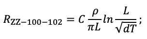
where C is a dimensionless coefficient describing the electrolyte content in the surrounding soil;
ρ is the soil resistivity, Ohm*m;
d is the ground terminal diameter, m;
T is depth, i.e. the distance from the ground surface to the ground terminal, m;
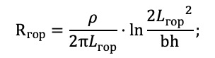
Horizontal electrode resistance:
Гор - Hor
where ρ is soil resistivity, Ohm*m;
b - is horizontal electrode width, m;
h - is horizontal electrode depth, m;
Lhor is horizontal electrode length, m.
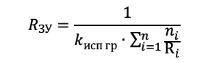
Electrical impedance of the grounding arrangement:
ЗУ - GA Исп гр - Util
where n is the number of sets;
kutil is the utilization ratio;

ЗУ - GA
Исп гр - Util
Гор - Hor
Ом - Ohm
The estimate resistance of the grounding arrangement is 24,83 Ohm.
List of required materials:
| Item # | Designation | Description | Quantity | Unit weight, kg |
| 1. | GL-21132 | GALMAR GL-21132 Lightning mast (3.0 m; for 1 m on a concrete foundation; galvanized steel) | 2 | pcs |
| 2. | ZZ-201-006-3 | ZANDZ Lightning mast, vertical, 6 m high, with a set of 2 wall fasteners (stainless steel) | 6 | pcs |
| 3. | ZZ-202-002 | ZANDZ Clamp to the lightning rod D42 mm for current collectors (stainless steel) | 5 | pcs |
| 4. | GL-11149 | Copper-plated wire (D8 mm) | 265 | m |
| 5. | GL-11551A | GALMAR Clamp for connecting current collectors (galvanized, painted steel) | 24 | pcs |
| 6. | GL-11545A | GALMAR Clamp for current collector (galvanized, painted steel) | 6 | pcs |
| 7. | GL-11562A | GALMAR Control clamp "wire+band" (D8+T<35; galvanized, painted steel) | 6 | pcs |
| 8. | ZZ-005-064 | ZandZ Clamp for connecting conductor (D14; up to 40 mm) | 18 | pcs |
| 9. | GL-11075 | GALMAR Copper-plated steel strip (30 * 4 mm) | 225 | m |
| 10. | ZZ-100-102 | ZandZ Electrolytic grounding set (horizontal; 3 meters long; for wet soils) | 6 | pcs |
Appendix: design in DWG and PDF formats
Click here to view the diagram in full.
Молниеприемник-мачта высотой 6 м на держателях - 6 m lightning mast on supports
Для молниеотводов высотой 6 м: - For lightning arresters of 6 m high:
Молниезащита и заземление цеха в гравийном грунте - Lightning protection and grounding of a workshop located in a gravelly soils
Зона защиты от прямого удара молнии - Protection zone against direct lightning strike
Фасад в осях - Façade within axes
Молниеприемник-мачта высотой 3 м на бетонном основании - 3 m lightning mast on a concrete foundation
Стадия - Stage
Лист - Sheet
Листов - Sheets
DWG and PDF files are available for download by the signed-in users only.
Need a design of grounding and lightning protection? Order now by contacting the ZANDZ Technical Center
Related Articles:
.jpeg) Exemplary Design of Grounding System for a Control Station Using Coke Fines
Exemplary Design of Grounding System for a Control Station Using Coke Fines
 Shopping center lightning protection project