Definition of equipotential bonding system
The equipotential bonding system (EBS) is performed in order to ensure electrical safety, at the difference of voltage of metal parts available for contact with a person, by their electrical connection to a neutral protective conductor.
Excess voltage arises, as a rule, in the breakdown of the insulating layer, as well as under the influence of pulses of the electromagnetic field and the currents of the grounding systems.
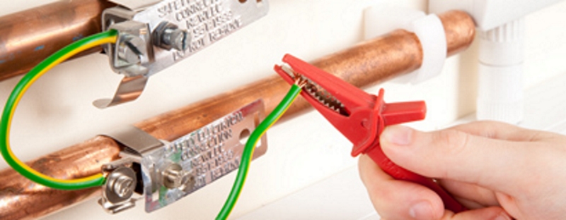
The principle of operation consists in combining all current-conducting elements with the main grounding bus using the radial circuit of their connection by equipotential bonding conductors.
Depending on the grounding scheme of the electricty mains at the facility, PEN or PE conductors are connected to the MGB, connecting it to the grounding device.
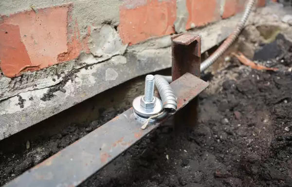
The connection of the conductive parts is carried out using welding or bolted connections with separate conductors, to which high demands are placed regarding their continuity and the choice of the cross-section. All connections of the EBS elements must be accessible for inspection and adequately protected from mechanical damage and environmental influences.
Rules for the organization of EBS contain the following regulatory documents:
- IEC standard 364-4-41;
- |||UNTRANSLATED_CONTENT_START|||ГОСТ 13109-97 Электрическая энергия.|||UNTRANSLATED_CONTENT_END||| Electromagnetic compatibility of equipment. Quality standards of electricity in general purpose power supply systems;
- GOST R 50571.1-93 Electrical installations of buildings. Main Provisions;
- GOST R 50571.2-94 Electrical installations of buildings. Key features;
- Electrical installations code (EIC, 7th edition)
The need of EBS for SCS
The structured cabling system (SCS) is integrated into the building infrastructure to automate the information transfer processes.
SCS is organized for the purpose of control, monitoring and management of economic services at the enterprise, guided by the standards of GOST R 53245-2008 "Informational technologies. Structured cable systems. Installation of the main components of the system. Test methods "and international standards EN50173, ISO 11801, TIA 568, EN 50174-3.
A structured cabling system consists of structural subsystems that perform strictly defined functions:
- subsystem of the workplace,
- horizontal subsystem,
- building backbone cabling subsystem,
- subsystem of the backbone cabling system of a complex of buildings.
The role of SCS in the functioning of the corporate information system of a modern enterprise can not be overemphasized: the safety and reliability of various operations performed in the course of activities, the uninterrupted operation of information systems depend on the literacy of its organization.
A structured cabling system can break down due to an electrical leakage, due to equipment failure (low-frequency currents), or under the influence of an electromagnetic field from nearby devices capable of accumulating the energy of signal currents and giving it away in the form of electromagnetic interference (high-frequency currents).
High-frequency currents with a low amplitude level, as a rule, do not pose danger to humans, but can have a negative impact on the quality of data transmission. To remove and disperse such unwanted currents that are accumulated on the SCS cable screen, functional grounding is performed.
In order to prevent disruptions in the operation of structured cabling systems under the influence of low frequency currents, when there is excessive voltage in its elements, and to protect users from electric shock, a system of potential equalization is performed.
But if a PEN-conductor is used, in which the functions of both the zero protective and the zero working conductors are connected, they are designated by the letter C (from the English word Combined).
Now, knowing the basic letter designations, you can easily decipher the abbreviations that mark different types of grounding systems.
Ways to organize EBS for SCS
When organizing the system of equipotential bonding of SCS, it is necessary to perform a qualitative protective grounding of all non-insulated metal parts of its equipment in accordance with the international standard EN50174-2: 2009.
Protective grounding must be performed for both unshielded and shielded cabling systems, using a single conductor with low resistance at low frequencies.
Equalization of potentials in SCS is achieved by combining all the current-carrying elements (mainly enclosures and switching equipment) that enter into it, with local grounding buses located as close as possible to the backbone cable connections, usually at the locations of the switchgear installation, inside telecommunications rooms. The local grounding buses are connected to the MGB of the electrical input of the building. The potential difference between any two points of the grounding system should not exceed 1 V (alternating current, rms value).
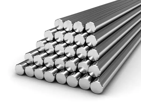
To eliminate the need to install a number of separate ground conductors for connecting local buses to the MGB, the norms of the international standards EN 50174-2: 2009 and EN 50310: 2009 prescribe installation of a grounding conductor - a copper-bonded conductor with a diameter of 8 mm wherever possible.
Each separate building has its own MGB. All metal parts of network equipment and SCS switching equipment are grounded through the mounting bases to the grounding buses of individual zones. To eliminate this problem, it is proposed to build an alternative conductor with low impedance between the buildings, connecting the MGB of separate buildings and providing equipotential bonding between them. Trunk cable with metal armor, grounded on both sides acts as such a conductor.
However, laying of a copper cable between the buildings requires installation of protection elements against atmospheric overvoltage, which in many ways complicates the task of arranging the EBS. The use of a cable shield as a potential equalization conductor is not possible. In this case, experts recommend not to use copper twisted-pair of LAN cables in favor of a more secure analog of fiber, the structure of which includes dielectric armor and does not have any metal elements in its composition, and therefore won't become a conductor of unwanted currents.
See also:
- Grounding. What is it and how to make it
- Lightning protection in a single-family house: standards calculations, examples
- What is a disspation array device and how it works?
- Useful materials for designers: articles, recommendations, examples
- Soil resistivity table
Related Articles:
 Why Cannot Vertical Earthing Devices Be Installed Close to Each Other?
 Electrolytic Grounding in Permafrost Soils: Should Vertical of Horizontal Electrodes Be Used?


