Открыть картинку в новой вкладке
Task
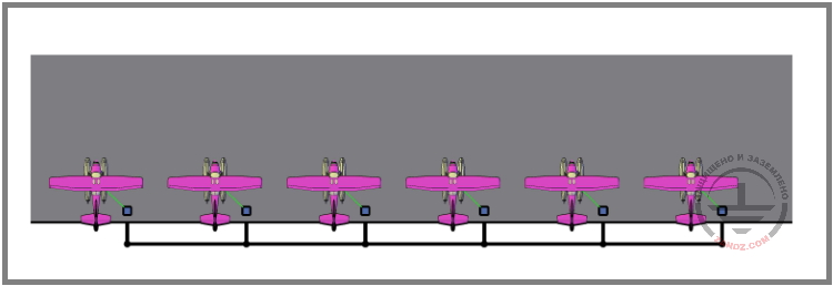
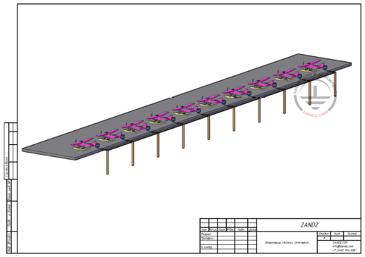
Facility: a flying line; number of airplanes: 10; soil type: clay loam; soil resistivity: 100 Ohm*m. Calculations are required to develop a grounding arrangement design to comply with the effective regulatory and technical documents.
General data
The technical solutions adopted in design documents comply with the requirements of environmental protection, sanitary and hygienic, fire safety as well as other standards effective in the territory of the Russian Federation and provide operation of the facility in a way safe for lives and health of the people, while complying with the events provided for by design drawings. Design documentation complies with the requirements of the effective regulatory documents.
This section considers the solution to develop a grounding arrangement for the flying line.
The grounding arrangement is performed in accordance with the EIC Rev. 7, the RTOEIC, GOST 12.1.018.
Resistance up to 100 Ohm for the grounding arrangement intended to protect against static electricity is allowed according to Chapters 1.7 and VII of the Electrical Installations Code (EIC).
The grounding arrangement is made from horizontal and vertical grounding arrangements. A copper-plated grounding electrode d14.2 mm installed in the locations of connection to the airplane grounding boxes is used as a vertical grounding arrangement. All grounding arrangements are combined with a horizontal grounding electrode (steel copper-plated bar having cross-section 30 x 4 mm). Depth is 0.5 to 0.7 m.
The airplanes are grounded using ground wires with fixed plugs connected to the airplane sockets.
Ground terminal resistance calculation:
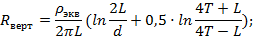
Vertical electrode resistance:
Верт - Vert
Экв - Eq
where ρэкв ρэкв is soil resistivity, Ohm · m;
L L – is vertical electrode length, m;
d d – is vertical electrode diameter, m;
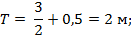
T T – is depth, i.e. the distance from the ground surface to the ground electrode, m;
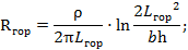
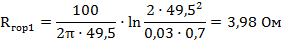
Horizontal electrode resistance:
Гор - Hor
where – is soil resistivity, Ohm · m;
b b is horizontal electrode width, m;
h h is horizontal conductor depth, m;
is horizontal electrode length, m.

where t t – is electrode top depth, m
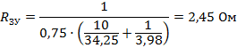
Electrical impedance of the grounding arrangement:
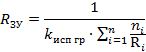
where n n – is number of sets;
kисп kисп – is utilization coefficient;

Ом - Ohm
ЗУ - GA
Исп - Util
М - m
The rated resistance of the grounding arrangement is 2,45 Ohm.
List of required materials:
| Item No. | Name and technical characteristics | Part number | Unit of measure | Amount | Unit weight, kg |
| 1 | ZANDZ Copper-clad threaded grounding rod (D14; 1.5 m) | ZZ-001-065 | шт. | 20 | 1,9 |
| 2 | ZANDZ Threaded coupling | ZZ-002-061 | шт. | 11 | 0,082 |
| 3 | ZANDZ Takeoff tip | ZZ-003-061 | шт. | 10 | 0,074 |
| 4 | ZANDZ Guide head for jackhammer attachment | ZZ-004-060 | шт. | 4 | 0,088 |
| 5 | ZandZ Clamp for main conductor connection (D14; up to 40 mm) | ZZ-005-064 | шт. | 20 | 0,16 |
| 6 | ZANDZ Conductive grease | ZZ-006-000 | шт. | 2 | 0,312 |
| 7 | ZANDZ Waterproofing tape | ZZ-007-030 | шт. | 7 | 0,422 |
| 8 | ZANDZ Attachment to the hammer (SDS max) | ZZ-008-000 | шт. | 1 | 0,478 |
| 9 | GALMAR Copper-plated bar 30 x 4 mm (bundle, 50 m) | GL-11075-50 | шт. | 1 | 0,98 |
| 10 | GALMAR Copper-plated bar 30 x 4 mm (bundle, 20 m) | GL-11075-20 | шт. | 1 | 0,98 |
| 11 | Box for grounding connection | шт. | 10 | ||
| 12 | Grounding wire with the attached plug to connect to the airplane socket | шт. | 10 |
Appendix: design in DWG and PDF formats
Need a design of earthing and lightning protection? Order now by contacting the ZANDZ Technical Center!
Related Articles:
 Electrolytic Grounding in Permafrost Soils: Should Vertical of Horizontal Electrodes Be Used?
 Grounding and lightning protection: questions and issues arising in the design process (webinar series)