The third part of the article "Methodics of calculation of SPD load currents"
One can hardly doubt, that the solution in the frames of the substitution circuit with the distributed parameters in a common case is most authentic. The advantages are very obvious, when it is necessary to have a current and voltage distribtuion along the studied part of the overhead line. But for a choice of SPD, such information is almost always exessive. It is enough to know currents only at the ends of the overhead lines, where SPDs must be installed. There is nothing else for their choice. In this case, it is reasonable to try substitution scheme with the concentrated parameters, for example, П-shaped which is shown in fig. 7.
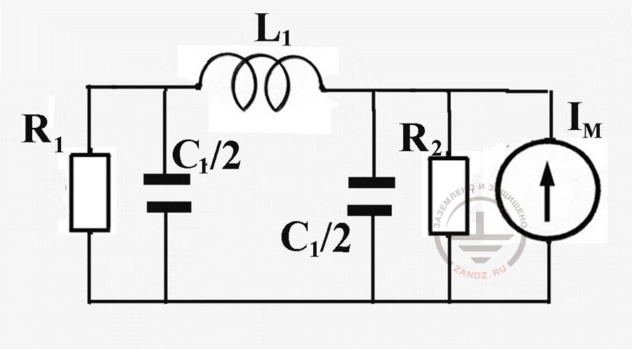
Fig. 7. Susbstitution scheme for the estimation of lightning current share in the ground electrode system of the object and overhead power transmission line feeding it
It includes inductivity of the line cut (L1), ground resistance on its ends ( R1 and R2) and wires capacity (C1). The latter is divided in two for symmetry and is connected to the ends of overhead lines, parallely to ground resistances. Each capacity creates an additional channel of lightning current drainage to the ground. Its conductivity should be compared with the conductivity of ground resistances. Elementary estimation will allow to understand if it is possible to neglect considering capacities. Their reactive resistance to AC is defined as

(10)
where ω is the main frequency determining the lightning current pulse front. Presenting the front with the duration Tf as a half of sinusoidal period, for the calculation pulse of the lightning current 10/350 ms, we get

Since the running capacity of a long conductor is estimated by the value of order 10 pF/m and the length of a part of low-voltage overhead power transmission line is hardly greater than 1000 m, after the substitution in (10) we get xC ≈ 630 Ohm, which is much greater than the typical values of grounding resistances. It gives ground to exclude the wire capacity out of the substitution scheme of the overhead line and hold the calculation according to a very simple scheme fig.8.
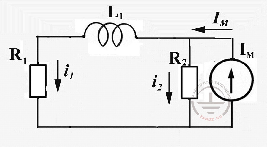
Fig. 8. Susbstitution scheme for the estimation of lightning current share in the ground electrode system of the object and overhead power transmission line feeding it
You should not be afraid, that its solution comes down to differential equations, though very simple, linear ones. According to the law of Kirchhoff


(11)
Here index 1 characterizes overhead power transmission line with the inductivity L1 and ground resistance on its substational end R1, and index 2 protected object with the ground resistance R2. The sum of currents in the overhead power transmission line and in the object ground electrode system i1(t)+i2(t) is equal to lightning current IM(t). Where

(12)
Equation (12) would have an elementary analytical solution, if not IEC compliers, who created a too complicated expression for the analytical idea of lighting current (9). We have to resource to numerical method, but, this time, not complicated one. In order to build the solution algorithm, it is enough to switch to infinitely small current and time increments to their final small increments


(13)
Here i1(tk) means current i1 at the calculated time moment tk, and, correspondingly i1(tk+1) - the same current in the next calculated time period tk+1 =tk+Δt. Substitution of these expressions in (12) allows to find the value of the sought current in the time moment tk+1 by the counted value for time moment tk


(14)
The algorithm of the numerical calculation by (14) is very simple:
- The value of inductivity of the studied cut of the overhead power transmission line L1 is set, as well as the ground resistance on its substational end R1 and at the object, hit by lightning, R2.
- The amplitude of lightning current Imax, for which the calculation will be made, is being chosen.
- The time interval of the calculation Δt is being chosen (recommendations on the choice of this parameter will be given in section 5).
- For the source value of time t=0 the source current value i1(t) =0 is recorded.
- The next time value, increased to the time pitch Δt compared to the precedeeing value is being defined.
- According to expression (9) for the new time value t, the current value of the lightning current IM (t+Δt) is defined.
- The found value of the lightning current IM (t+Δt) and current value, counted at the previous calculation step (for the first calculation step this current is equal to zero!) are introduced to the first formula (14), by which, the new value of the current i1 for the next time moment t+Δt is defined; and then according to the second formula (7) we find the next current value i2 for the time moment t+Δt
In order to switch to the new calculation cycle, it is necessary to increase time to another calculation interval Δt and remember that to define each new value of current i1, its value from the previous calculation stage is introduced into formula (14).
The comparison convinces in an almost complete overlap and this way, justifies the simplified calculation approach.
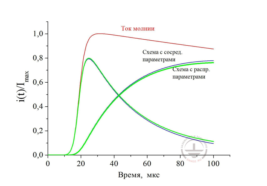
Fig. 9. Comparison of the calculation results by the schemes with the distributed and concentrated parameters. Source calculation parameters are similar to the ones used in fig. 5
Ток молнии – lightning current
Схема с сосред. Параметрами – scheme with concentrated parameters
Схема с распр.параметрами - scheme with distributed parameters
Время - time
Lightning current distribution at a direct lightning strike into overhead power transmission line 380/220 V is not different by the solution algorithm from the one we've just studied. Now there are two chain parts with inductivities - part to the substation with the inductivity L1 and part to the protected object with inductivity L2. This way, the first calculation expression (11) changes a bit


(15)
and then follows the differetial equation (14), which now has a form


(16)
Calculation algorithm doesn't change. An exception is only calculation of inductivity L2 for a part from the lightning strike point to the protected object by formula (16) and introduction of lightning current into this formula IM(t) at the current distribution i(tk+1) for time moment t+Δt. For example in fig. 10, we see calculation charts of the current at a lightning strike into the middle of the overhead power transmission line 200 m long at the ground resistance of the substation R1 = 0,5 Ohm and ground resistance of the object R2= 4 Ohm.
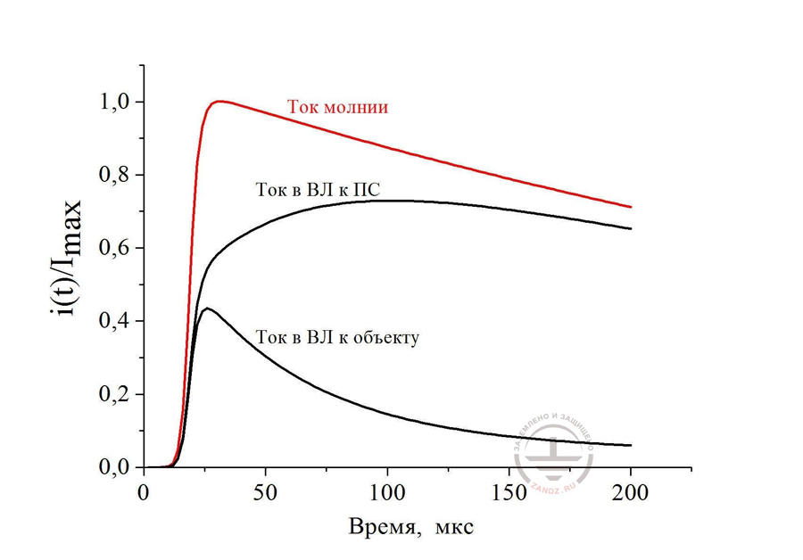
Fig. 10. Current distribution at a lightning strike into the middle of overhead power transmission line 200 m long with ground resistance of 0,5 Ohm at the substation and 4 Ohm at the object
Ток молнии – lightning current
Ток в ВЛ к ПС – current in overhead power transmission line to the substation
Ток в ВЛ к объекту – current in overhead power transmission line to the object
Время, мкс – time, ms
The fact, that maximums of the branched current do not principally coincide in time and the shape of pulses is sharply different from lightning current pulse, taken for the calculation with parameters 10/350 ms is worth paying attention. It forces to make cautious calculations of any thermal consequences of current impact, made by the standardized values of the pulse specific energy from IS-153-34.21.122-2003 or from IEC standard 62305.
E. M. Bazelyan, DEA, professor
Energy Institute named after G.M. Krzyzanowski, Moscow
Read more "4. When it is impossible to get along without a circuit with distributed parameters"
See also:
- Video recording and transcript of the webinar with Prof. E.M. Bazelyan "Why do we need SPDs"
- Principles of choosing surge arresters in low-voltage electric networks on the example of Leutron devices
- Free webinars for designers of grounding and lightning protection
- Grounding and lightning protection projects in dwg, pdf formats
- Free consultations and assistance in calculation of grounding and lightning protection
Related Articles:
 Lightning Protection of Large Territories: Parks, Grounds, Plant Territories. Page 1
 Lightning Protection of Large Territories: Parks, Grounds, Plant Territories. Page 2
 Lightning Protection of Large Territories: Parks, Grounds, Plant Territories. Page 3