The second part of the article "Methodics of calculation of SPD load currents"
Solution of the task about division of the lightning current between the overhead lines, powering the hit object, its ground electrode system, as it was said above, requires knowledge of linear value of inductivity L and capacity C of the overhead lines, and also its linear resistance R. The process is described by the equations in partial derivatives


(1)
They mean, that the voltage reduction on an infinitely small piece with the length of dx is defined by the voltage drop from current i on the resistance and inductance (if the current changes from time to time) or this piece, and reduction of current on the same piece in the absense of the cross conductivity is only defined by the displacement current via its capacity. It is easy to bring the repeated differential equation to the wave one, which is more convenient for a computational solution.

(2)
At that, private derivatives are presented by the following difference expressions:

- for k point in n time moment

- for n time moment in k point,

- for n time moment in k point.
Here Δx and Δt are calculation pitches along the line and time respectively. Derivatives for currents look the same. Considering expressions for the derivatives, the equation to define voltage in calculation nods of difference schemes at a direct pass in the direction of the defeated object to substation can be written in the form of

(3)
where A = LC/Δt2, and Unk means voltage in time moment tk at the calculation point of the line with Xn coordinate.
So, in order to find voltage in the point with the coordinate xn in the next calculation time moment tk+1, we need to know voltage values in this point for the previous time moments tk and tk-1 and also voltage values in the points with the coordinates xn-1 and xn+1 for time moment tk. If the initial (at t=0) voltage distribution on the line is set, and usually it is equal to zero, then the difference expression (3) allows to calculate voltages of all calculated intervals, except the first and the last one, by the consequitive pass from the start of the overhead line to its end. Their determination requires attraction of boundary conditions, which describe power circuit in the beginning of the line and load on its end. For example, at a puncture of wires insulation by a thunder overvoltage, the ends of wires of overhead power transmission lines turn out to be connected to ground electrodes of the protected object and the feeding substation. Then, at the substation end, to which the substitution scheme on fig. 2 corresponds the voltage of the olast node is defined via current in grounding resistance of the substation RP
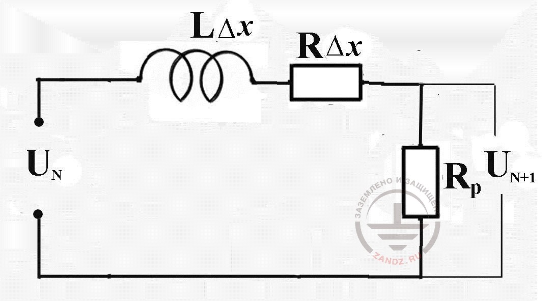
Fig. 2. The substitution scheme for the calculation of voltage of the last scheme node and current in the ground electrode system of the substation RP

where

(4)
Here N is a full number of spacial cuts of the overhead line ith the length at ∆x, and the second calculation formula (4) was recieved by a transfer of the linear differential equation for the voltage on the contour

(5)
in the different form, and ink value - is an earlier found current for time moment tk, and values L0 = ∆xL and R0 = ∆xR - inductance and resistance of the calculation cut ∆x.
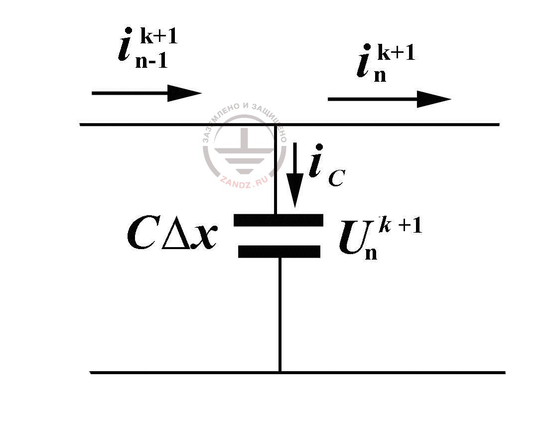
Fig. 3. To the calculation of currents in overhead power transmission lines at the reserve pass
Now, when we know the current value in the end of the line to the next time moment tk+1 and all the voltage values in the scheme nodes, it is possible to define currents in all the pieces, guiding by the elementart substitution scheme by a reverse pass, moving from the end of the overhead power tranmission line to its beginning, fig. 3. As we can see, the current along the line changes at the expense of the capacitance current iC, thanks to which, the charge and the voltage on the calculation piece capacity changes. That is why

(6)
where

(7)
The first node of the calculation scheme, where there is the lightning current and grounding resistance of the defeated object, requires additional attention. Substitution scheme for this node (fig. 4) allows to finish the calculation cycle, expressing a still unknown voltage U1k=1 via the current value of the lightning current Iм (tr+1) and already calculated current i1k+1
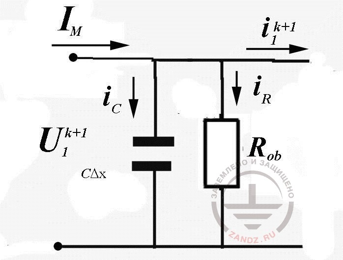
Fig. 4. The scheme of substitution of node №1 of the calculation scheme
Here i1k+1+iR+iC=IМ, which gives (similarly to the calculations held above)

(8)
All values for the sought parameters for the calculation time moment tk+1 are found. We can view the next time step and so on, until the required time moment is achieved.
The algorithm given may seem to be too lengthy, but there is no complexity in it at all. And the direct pass, required for determination of voltage nodes of the calculation scheme and the reverse pass for calculation of currents of calculated pieces of the overhead power transmission lines practically doesn't change. Only calculation of lengthy grounding buses is an exception. There it is required to consider the conductivity of current drainage to the ground (the question will be studied below). The changes concern only the conditions on the line ends, where it is necessary to calculate currents in an ordinary substitution scheme with the concentrated parameters - the task is quite habitual for an engineer-electrician.
In fig. 5 and 6 we see the results of the numerical calculation of the task viewed above.
The mathematical expression for lightning current is taken from IEC standard and from the national instruction IS-153-34.21.122-2003.

(9)
It is worth remembering, that it is quite inconvenient for the analytics and numerical calculations, especially if the source parameters k, t1 and t2 are chosen for the description of a typical pulse 10/350 ms.
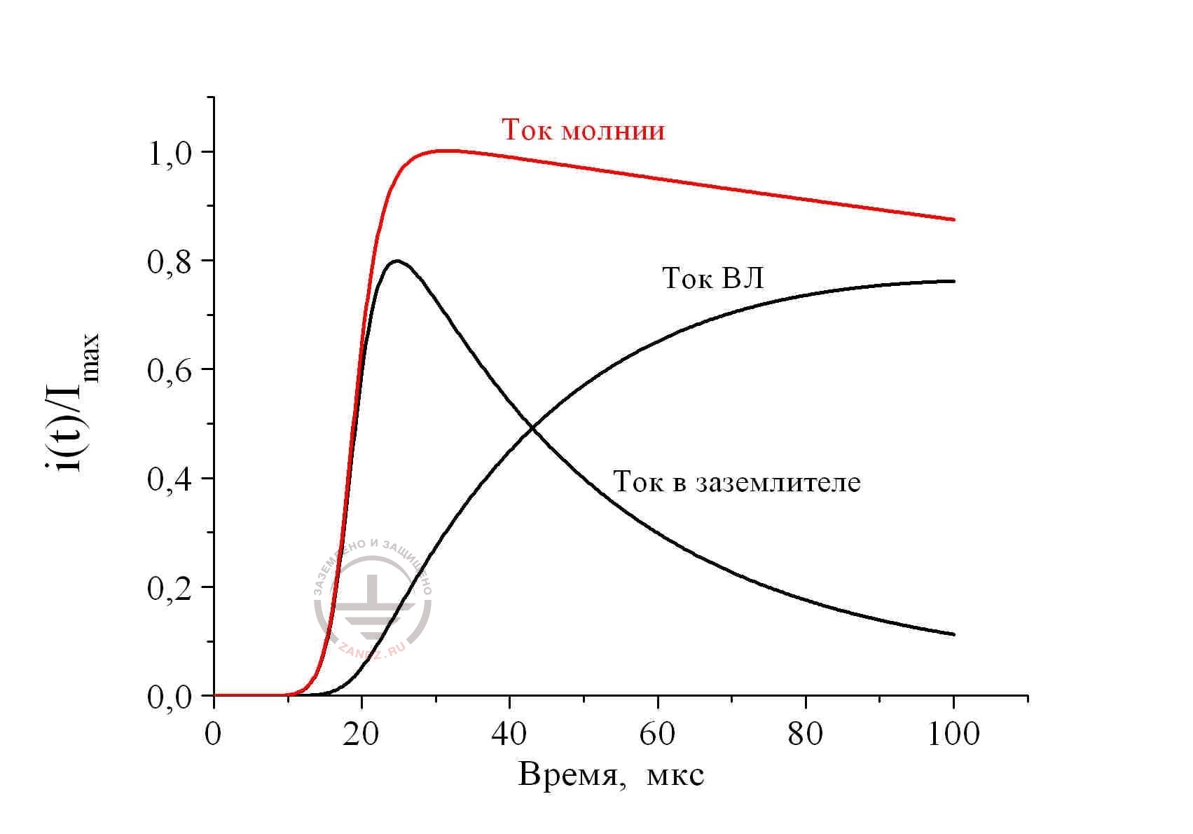
Fig. 5. Distribution of lightning current 10/350 ms between the metal utilities of the defeated object with the ground resistance of 10 Ohm; the length of the overhead line 300 m: ground resistance of the substation 1 Ohm
Ток молнии – lightning current
Ток ВЛ – current in overhead power transmission lines
Ток в заземлителе – current in ground electrode system
Время, мкс – time, ms
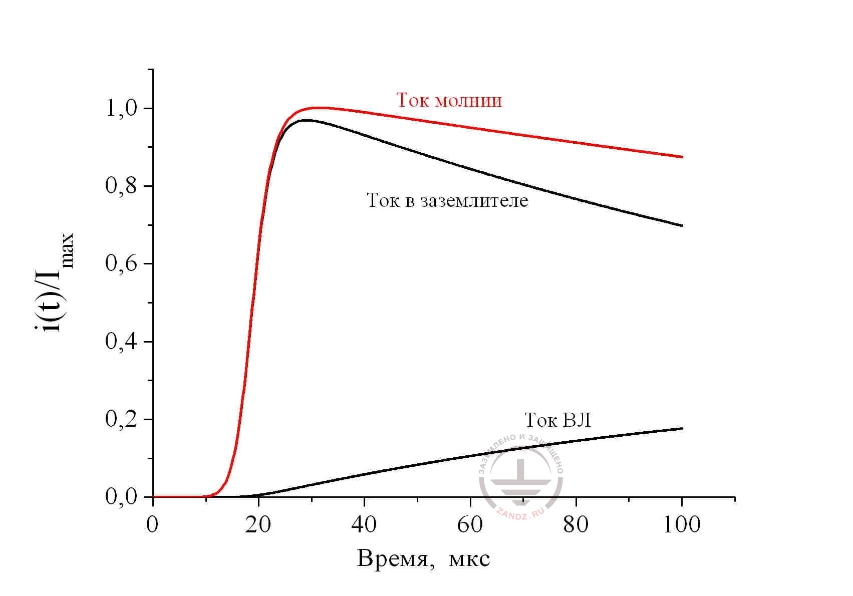
Fig. 6. Distribution of lightning current 10/350 ms between the metal utilities of the defeated object with the ground resistance of 1 Ohm; the length of the overhead line 300 m: ground resistance of the substation 1 Ohm
Ток молнии – lightning current
Ток ВЛ – current in overhead power transmission lines
Ток в заземлителе – current in ground electrode system
Время, мкс – time, ms
The presented solutions are made for the piece of overhead power transmission line 300 m long. Ground resistance of the defeated object is taken equal to 10 Ohm for fig. 5 and 1 Ohm for fig. 6; ground resistance to the substation was equal to 1 Ohm. It is easy to make sure, that the obtained results do not have much in common with the company prescriptions fig. 1, where it is recommended to take the current in the ground electrode of the defeated object at any consequences equal to 50% from the lightning current. In fact, its share can change significantly within time (calculation conditions for fig. 5) and the amplitude value may hardly coincide with the lightning current (calculation conditions in fig. 6). Consequently, share of the current branching into the overhead power transmission lines via the activated SPD, doesn't remain constant. Time parameters of the pulse, which loads them, are slightly similar to the standardized pulse of the lightning current. This circumstance makes the numerical calculation necessary. Without it, it is impossible to estimate the energy contribution into SPD and choose a certain type of the protective device.
Soutions, which are presented here, are made with the time pitch of 1 ns. So, the calculation interval of 100 ms was split into 105 time pitches. The spacial pitch is taken equal to 1 m. Consequently, it was required to make 3x10⁷ calculation cycles. However, the calculation lasted for not more than 1 minute. As you can see, computer should not be neglected!
The question about consideration of SPD parameters in the calculation is consistent. It is easy to make cure, that there was no place for them in the calculation schemes. This is consistent, because own resistance of the activated SPD is little in comparison to the grounding resistance of the object or substation and practically doesn't tell on the current value.
So, no universal schemes with the fixed percentage shares of the lightning current cannot bring to authentic ideas of the SPD current load. A right, specific decision is required and the main questions is to avoid lengthy calculations, which are not always justified.
E. M. Bazelyan, DEA, professor
Energy Institute named after G.M. Krzyzanowski, Moscow
See also:
- Video recording and transcript of the webinar with Prof. E.M. Bazelyan "Why do we need SPDs"
- Principles of choosing surge arresters in low-voltage electric networks on the example of Leutron devices
- Free webinars for designers of grounding and lightning protection
- Grounding and lightning protection projects in dwg, pdf formats
- Free consultations and assistance in calculation of grounding and lightning protection
Related Articles:
 Lightning protection of residential and public buildings - answers to frequently asked questions in the design
 Lightning Protection of Large Territories: Parks, Grounds, Plant Territories. Page 1
 Lightning Protection of Large Territories: Parks, Grounds, Plant Territories. Page 2
 Lightning Protection of Large Territories: Parks, Grounds, Plant Territories. Page 3