|
Induced current in 50x50 m loop
|
RU
|
EN
|
|
Наведенный ток в контуре 50х50…
|
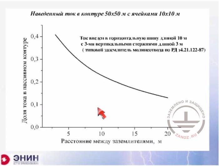
Induced current in 50х50 m loop with 10x10 cells
|
|
Ток введен в горизонтальную шину…
|
The current is introduced in the horizontal bus 10 m long with 3 vertical rods 3 m long (a typical ground electrode system for a lightning rod according to RD 34.21.122-87
|
|
Доля тока в пассивном контуре
|
The share of current in a passive loop
|
|
Расстояние между заземлителями, м
|
Distance between ground electrode systems, m
|
Look what happens with the current. If I put the ground electrode system at a distance of 5 meters, then both PUE and RD 34 permit a situation when about 35% of the lightning current comes into the ground electrode system of the building. Even if I install my ground electrode system hell knows where, somewhere at a distance 20 meters, then about 15 to 20% of the current will enter the grounding device of the building anyway. So it turns out that if you want to make a decent individual ground electrode system, you should move it to a very long distance.
The potential at the lateral side of the passive ground loop
|
RU
|
EN
|
|
U(x)/I, Ом
|
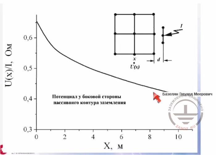
U(x)/I, Ohm
|
|
Потенциал у боковой стороны пассивного контура заземления
|
Potential near the side of passive ground loop
|
|
Х, м
|
X, m
|
And if you have nowhere to move it, then you are left with only one option. Make an individual deep ground electrode system and isolate it at a depth of 20 -30 meters. This is the only case it will work more or less properly. And I also need to take into account the following. Look at this situation. In short, it is very relevant. Here you have a foundation of the building, and here you have an individual lightning rod and an individual ground electrode system for the rod. So due to the fact that a part of the current is still transferred to this loop, you will have protected buildings in the vicinity, as the lightning strike has been intercepted by the lightning rod. The step and touch voltages will appear here, which will affect people quite seriously. For example, it can lead to the potential surge on the railing of the building, at the level of 10, 20 or even 30 kV. It appears that the individual ground electrode system, generally speaking, protects virtually against nothing. The individual ground electrode system ultimately turns out to be a myth. It may comfort the customer to some extent, but no more than that. Do you want to make a serious individual ground electrode system? You should bury it deeper and isolate it in any case.
Step and touch voltage
|
RU
|
EN
|
|
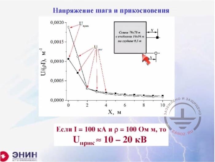
Напряжение шага и прикосновения
|
Step and touch voltage
|
|
Сетка 70х70 m с ячейками 10х10 м на глубине 0.5 м
|
70х70 m mesh cage with 10x10 m cells at a depth of 0.5 m
|
|
Если I=….
|
If I=100 kA and ρ=100 Ohm m, then Utouch ≈10-20 kV
|
I've already told you about the step voltages. The step and touch voltages can be quite large, even if the ground electrode system is moved far from the building foundation.
RD 34.21.122-87
|
RU
|
EN
|
|
РД 34.21.122-87
|
RD 34.21.122-87
|
|
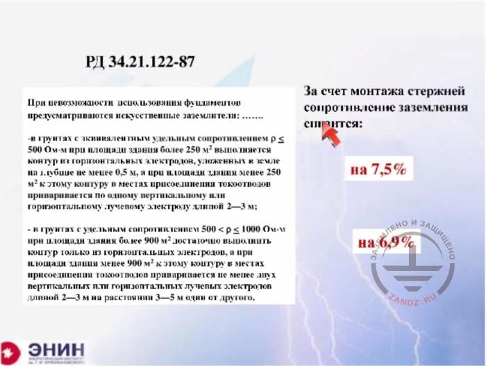
***Текст мелкими буквами в переводе не нуждается. это выдержка из стандарта, есть ее пересказ в основном тексте
|
|
|
За счет монтажа стержней сопротивление заземления снизится:
|
After the installation of ground rods, the grounding resistance will decrease by:
|
|
на 7,5%
|
by 7.5%
|
|
на 6,9%
|
by 6.9%
|
And now there is one thing I can show you. If you read about various lightning protection devices, then you'll find the words that I have pulled out of the RD 34 standard. Look what it says. It says something like that. Imagine your ground electrode system is not very good. For example, you have a building area of 250 square meters measured by the foundation. The foundation cannot be used as a grounding system. For example, it is made from brick. In this case, you have to make a horizontal loop along the perimeter of the building. Let's assume that you've made a horizontal ground loop. If the soil resistivity is higher than 500 Ohm m, then it is necessary to connect vertical electrodes 2 to 3 meters long to the loop in places where down conductors are fastened to it. If your building has a foundation area of 250 square meters, this means that the length and the width of the building are around 16 meters. If you have a building 16 meters long, you will have maximum two down conductors because they will be installed with a step of 25 meters. This means you are obliged to drive two two-meter vertical ground rods into the soil. The question is what will they give you? Look, that’s their effect. In this case, they will change the grounding resistance by 7.5%. Is it really worth taking the trouble to get such a modest result? The same recommendation is contained in RD 34 in respect of the soil with a resistivity higher than 1000 Ohm meters. The standard recommends driving in not just one but two rods. We conducted calculations for this case, and it turns out the grounding resistance changes by 7%. So again, it is within the measurement error. Then we began looking at the following thing.
Influence of vertical ground electrodes
|
RU
|
EN
|
|
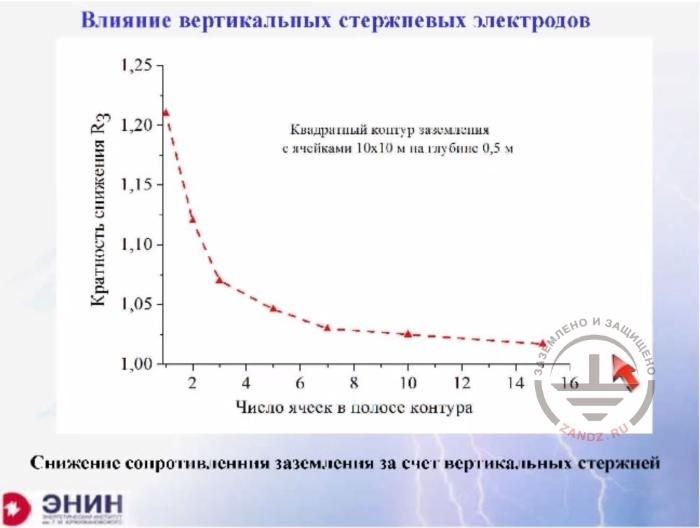
Влияние вертикальных стержневых электродов
|
Influence of vertical ground electrodes
|
|
Кратность снижения R3
|
Decrease ratio R3
|
|
Квадратный контур заземления с ячейками 10х10 м на глубине 0,5 м
|
Square ground loop with 10х10 m cells at a depth of 0.5 m
|
|
Число ячеек в полосе контура
|
Number of cells in the loop area
|
|
Снижение сопротивления заземления за счет вертикальных стержней
|
Grounding resistance decrease due to vertical rods
|
OK, you have a ground loop. For example, you have a horizontal mesh. Let's assume the mesh cell is 10 x 10 meters. And I will drive two-meter vertical electrodes at each node of the mesh. The question is what will they give? Let's see. If there is only one cell, then they will reduce the grounding resistance by about 20%. If you have 10 cells along the length, i.e. you loop is 100 by 100 meters, you will have your grounding resistance decreased by about 3%. And if you have a loop with cells 15 by 15 meters each, i.e. the loop is 150 * 150 meters then the reduction will be 2%. Look, you've driven 225 vertical bars in the soil spending 700 meters of rebars on that, and it appears you've buried this iron in vain. Because that little change in the grounding resistance just makes virtually no effect. Nevertheless, these recommendations are included in PUE. For example, PUE proposes to drive two vertical rods near the entrance gate to the substation to reduce the step voltage. We've checked how this decreases the step voltage within the accuracy of the calculations. Here's the result.
Pulse current spreading, long bus
|
RU
|
EN
|
|
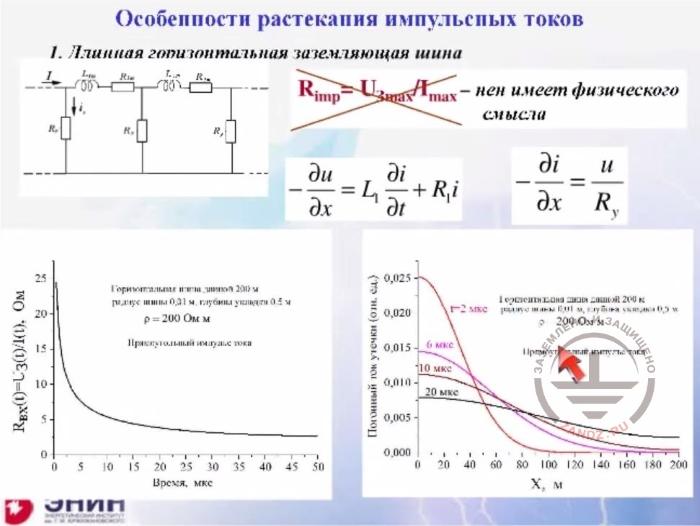
Особенности растекания импульсных токов
|
Features of pulse current spreading
|
|
1. Длинная горизонтальная заземляющая шина
|
1. Long horizontal ground bus
|
|
- не имеет физического смысла
|
- does not make physical sense
|
|
Горизонтальная шина длиной 200 м
|
Horizontal bus, 200 m long
|
|
Радиус шины 0,01 м, глубина укладки 0,5 м
|
Bus radius 0.01 m, laying depth 0.5 m
|
|
ρ=200 Ohm m
|
ρ=200 Ohm m
|
|
Прямоугольный импульс тока
|
Rectangular current pulse
|
|
Погонный ток утечки (отн. ед.)
|
Linear leakage current (rel. unit)
|
|
Горизонтальная шина длиной 200 м
|
Horizontal bus, 200 m long
|
|
Радиус шины 0,01 м, глубина укладки 0,5 м
|
Bus radius 0.01 m, laying depth 0.5 m
|
|
Прямоугольный импульс тока
|
Rectangular current pulse
|
|
Ом
|
Ohm
|
|
Время, мкс
|
Time, microsecond
|
|
X, м
|
Х, m
|
I believe I still have about 10 to 5 minutes to talk to you about the following things. You can often hear “pulse ground resistance” phrase. What's this? They say that if you have a pulse current flowing, and the lightning current is a pulse current, then you'll have a higher grounding resistance than in the case of a direct current used for measurements. And this is true. This really happens, as due to the inductance of grounding electrodes the current flows at a certain speed into them, not instantaneously. This speed depends on the bus inductance and the soil resistivity. For example, right now I'm showing you how the resistance changes over time for a bus buried in the soil with a resistivity of 200 m Ohm. Look, this resistance has stabilized after about 50 microseconds, and it changes the rest of the time. And it changes ten-fold compared to a stable value. The pulse characteristics of the soil depend on at least two parameters.
Pulse current spreading , the loop
|
RU
|
EN
|
|
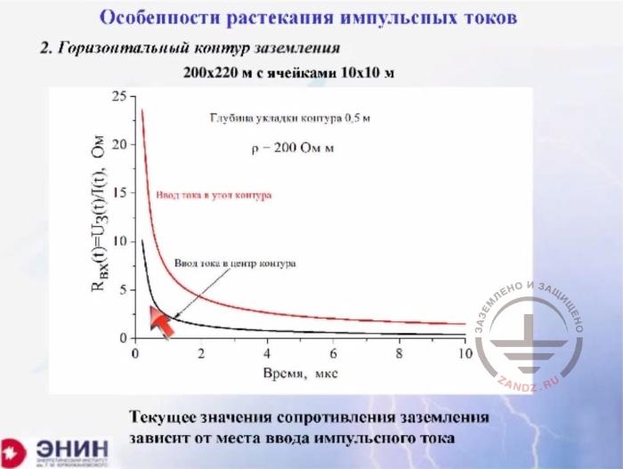
Особенности растекания импульсных токов
|
Features of pulse current spreading
|
|
Глубина укладки контура 0.5 м
|
Loop laying depth 0.5 m
|
|
ρ=200 Ohm m
|
ρ=200 Ohm m
|
|
Ввод тока в угол контура
|
Current input at the loop angle
|
|
Ввод тока в центр контура
|
Current input at the loop center
|
|
Время, мкс
|
Time, microseconds
|
|
Текущее значение сопротивления заземления зависит..
|
The momentary value of grounding resistance depends on the point of pulse current input
|
The first parameter is the soil resistivity, and the second parameter is not just the ground loop design but the current entrance point. Look at the example, please. I have a grounding loop for a substation 200 * 200 meters with a mesh 10 meters each. And I watched how the substation grounding resistance was changing over time after the current entered exactly in its center. Look, this grounding resistance decreases quite rapidly. And the second time the current enters the edge of the same ground loop. Here we have a very different picture. Calculating grounding resistance pulses is a very tricky and difficult task. If you decide that we need to discuss the grounding resistance calculations, I'll tell you what approaches exist to get the things done. And I just do not know any software of this kind developed abroad. But yes, there are Russian software products. There are actually two of them — one developed by our Institute and the other was made in the University of Vologda. They are well calibrated and compatible with each other, so they can be recommended for practical use.
Nonlinear processes in the soil
|
RU
|
EN
|
|
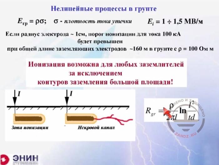
Нелинейные процессы в грунте
|
Nonlinear processes in the soil
|
|
σ – плотность тока утечки
|
σ – leakage current density
|
|
Если радиус электрода….
|
If the electrode radius is ~1 cm, then the ionization threshold for a current of 100 kA will be exceeded at the total length of ground electrodes ~100 m in the soil with ρ=100 Ohm m
|
|
Ионизация возможна для любых ….
|
Ionization is possible for all ground electrode systems excluding large-area ground loops!
|
|
Зона ионизации
|
Ionization zone
|
|
Искровой канал
|
Spark channel
|
Finally, I want to say one more thing that you have to keep in mind when designing a ground electrode system. The matter is this. The soil is a strongly nonlinear medium. Always keep the following fact in mind: the soil is a conductor, but a very poor one. The resistivity of the soil is a billion times higher than the resistivity of black metal. And because of this, when the current spreads in the soil, a strong electric field occurs in it according to Ohm's law. And if the electric field strength exceeds approximately 1 / 1.5 MV/m — and this is not particularly strong field — ionization processes will start occurring in the soil. These ionization processes change the picture of the current spreading greatly; and the most important thing these processes do is they lead to the formation of spark channels in the soil, which are virtually a continuation of lightning, but this time inside the soil.
Spark discharges along the soil surface, the experiment
|
RU
|
EN
|
|
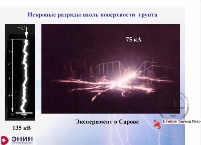
Искровые разряды вдоль поверхности грунта
|
Spark discharges along the ground surface
|
|
Эксперимент в Сарове
|
Experiment in Sarov
|
|
135 кВ
|
135 kV
|
|
75 кА
|
75 kA
|
I want to show you how they look. This is a photo of spark channels that have formed on the ground surface. The experiment was carried out by physicists of our nuclear center at a current of 75 kA. This is a fairly strong current, as approximately 15% of the lightning strikes have less current. Oh, I am sorry, 85% of lightning strikes have less current than shown in this figure. This size is approximately 30 meters. When formed along the surface of the soil, such channels change current draining conditions dramatically. And because of this, the ground electrode system must be designed with consideration of quite specific processes, which probably are worth discussing specifically. And if the issue is interesting for you, I'm ready to organize a special webinar where we will look at the consequences of the non-linearity processes in the ground. How to deal with them? And how can they be considered in the design?
Questions and answers session
I should probably go on with the answers to your questions if any. Alex, how are we doing? Huh?
- So far, we have only one question, and it more refers to the standards, so you probably may not be able to answer it. In general, there are regulations relating to the Ministry of Defense, that is, the construction of military facilities. This is VSP 22-02-07 Ministry of Defense. If you know this standard, what it your attitude towards the document, that is, how can you estimate it? To what extent it is correct or not correct?
- This is a special matter. Regulations of the Ministry of Defense are for restricted use only. So we probably cannot discuss these guidelines during our seminar.
- Thank you for your answer, it is quite clear. Colleagues, you can write your questions in the chat. As I look at it, no questions except this one have been asked yet. Edward Meerovitch, wait a bit.
- Then thank you for your attention.
- Thank you very much for an interesting coverage. Let's wait a few minutes for questions... Alexander, the grounding calculation software can be obtained either by contacting us or Mr. Eduard Bazelyan. Through contacting us is easier.
- Ilya: What is waterproofing in the building?
- So, there is a question about waterproofing, yes?
- Yes.
- I'll answer that question. The Russian norms state the following. This recommendation was written by the Structural Concrete Research Institute, which probably has been studying the current spreading in the concrete foundation for over a dozen years now. Their research revealed the following. If you have a bare reinforced concrete foundation buried in the soil, then the concrete hydrophobic properties are low. Your concrete is sucking moisture from the soil and about after two or three months of operation, the conductivity of the concrete does not differ from the surrounding soil conductivity. That is, we can assume that the rebars of the reinforced concrete foundation are simply buried in the soil. Concrete does not make any difference for the grounding resistance calculation. Similarly, the Concrete Research Institutes allows using reinforced concrete foundations if any bitumen-based waterproofing protection is applied on them. This is not an obstacle, too. But if the basement waterproofing is carried out using epoxy compounds or if the waterproofing is carried out as a special housing, then that's a different case. For example, in nuclear power plants, you have a foundation that, in fact, lies on a pan made of a polymeric material. In this case, the foundation cannot be viewed as a natural grounding. And we need to make a special grounding device ignoring the foundation. These are the regulations in Russia.
- Thanks for your answer. The next question, though a bit vague: where it is necessary to apply the information grounding?
- What?
- Where is it necessary to apply the information grounding?
- Information grounding, right?
- Yes, exactly.
- I've never heard such a term before. If the questioner explains what it is informational ground, I will try to answer that question, but for now, I do not know what it is.
- Ok, thanks. This question is: I have an electronic meter installed in a single-family house, which went out of order during a lightning storm. Or rather, will this counter fail during a thunderstorm if the house re-grounding has been carried out, and ground electrodes on the supports are bad? As far as I understand, the question is not only ...
- I understand. You know what? As for the damage to your electronic or non-electronic counters... The grounding resistance of your house will not influence them much. That's because the source of a surge, which will make the electronic counter inoperative, is the overhead power line that comes to your house. If the overhead line is made using a traditional method, that is overhead wires coming from the substation to your house and the distance between the conductors are somewhere between 30 to 40 cm, but the induced overvoltage is very large, then the risk that the counter fails is high. But if self-supporting insulated wires come to the house with the distance between the phases and the distance between the neutral conductor are equal simply to the thickness of the insulation, that is a few millimeters, then it's a different thing. Then it is improbable that these surges will bring your counter out of service. But in the first case, SPDs are needed to protect the counter, as we have already discussed during our previous webinars. Without them, the risk that the counter will fail is quite high.
- Thank you. Next question. What re-ground resistance value should be taken for the re-grounding on the entrance to the building? PUE does not specify this value.
- The fact, here's the thing. All grounding resistance values are standardized not for reasons of lightning protection. As for the lightning protection, our standards require a certain ground electrode system design. There are no requirements for the grounding resistance in our standards. RD 34 states that the lightning protection grounding is, in fact, a re-grounding system, so if you do not use a foundation for this purpose, then you only need to have three ground bars three to five meters long with a space of three to five meters from each other, too. This is quite enough. If your building needs a reinforced concrete foundation, then this concrete foundation is used as grounding you've called a re-grounding system. And no demands are made on it.
- Thank you. There is another question. How can you calculate the distance to the current electrode during the measurement, if there is only one vertical ground electrode? And there's also a sub-question. How do I deal with the distance to deep electrodes, i.e. in places where the length exceeds 20 to 30 meters?
- The situation is as follows. There's only one requirement here. For any extended grounding devices (I mean a horizontal bus and a vertical electrode), the step or a unit of distance for the measurements is the length of the electrode. So if you have a vertical electrode 20 meters long, then according to our standards you need to move away 20 * 3 from this electrode that is 60 meters for the current electrode. If you apply the methodology I've mentioned earlier, then you can shorten the distance by about three times. If you have an electrode deployed in an area, then we are talking about the maximum diagonal. And the unit of measurement will be the maximum diagonal. These are the requirements.
- Thank you. Next question. What type of grounding is most preferred for small residential buildings, such as cottages? Do I have to install a loop or different options are allowed? For example, a separate grounding for each down conductor.
- You know, I'll probably answer this way. I'll give you two answers. Russian standards allow using each down conductor's ground electrode as a ground electrode system. In my own house, I would not do it in any case. I would lay the bus along the outer perimeter of the building under the perimeter walk, which is made in any case to preserve the foundation. I would lay the bus under this perimeter walk, at a depth of 0.5 to 0.7 meters. Why? This solution is better than anything else. There are two criteria. First, such a bus more or less equalizes the potential distribution and the spreading of the lightning pulse current to make it less dangerous to people. This is the first thing. And the second thing is this. When you have this bus along the perimeter of the building, you can conveniently attach connect utility lines entering your home to the bus. And you have to connect them. Firstly, water lines, and secondly, a heating system, if you have it. Thirdly, cable shields. All this should be done using the shortest distance to reduce the step and touch voltage. And in this case, the loop that goes around the perimeter of the building has a huge advantage. And as for the cost of metal, you have to understand that when you build your own house, laying 40 extra meters of old water pipes or conventional reinforcing rods into the ground is not too expensive.
- Thank you. I did not understand the next question. I'll just read it aloud and perhaps you will understand it better. Returning to the information grounding, where it is necessary to apply it? So "information grounding" means the functional grounding of high-precision instruments.
- I'll start with what I've tried to tell you, but apparently, I spoke unclearly, because we were late for 7 minutes and I was anxious. Please understand that you are making an individual grounding you call functional or whatever you want. You are doing it in order to prevent the currents coming from other devices. If you have an individual ground electrode system and a ground electrode for a lightning rod near it, then currents will flow from one ground electrode system to the other anyway unless you've arranged a remote ground electrode system for your precision equipment. How can you make your ground electrode system a remote one? You can do this by moving it to a decent distance, e.g. dozens of meters away. Where do you move it? Moving it to the side is very difficult because if you do it you can run into a utility line where you do not expect it. Therefore, if you really need a precision ground electrode system, then you have one option: drill a well. Lower an insulated cable not connected to the ground in the well, for example to a depth of 20 to 30 meters. But the end of the cable should be bare and in contact with the soil. In this case, you will get a real remote ground electrode system with the pulse currents not entering it, so your equipment will remain intact. If you are ready to make such a ground electrode system, then it will be a truly individual system. And in general, any other options just do not make sense.
- Thanks for your answer. There is another question. And they become more and more complicated. What is used as a ground electrode system on offshore drilling platforms? And how can it be calculated?
- What I really do not know anything about is offshore drilling platforms. But I suspect there is no ground electrode system at all there, and the reason is the following. These platforms are most probably made of a metal. And most probably they are in contact with the sea water. The resistivity of seawater is less than 10 Ohm m and therefore whatever metal reinforcement structures are immersed into the water, the grounding resistance will be quite insignificant. So, in my opinion, you simply don’t have to make anything additionally. But maybe I do not know something specific about the offshore platforms, I just really do not know about them. But I believe this problem does not exist.
- Thanks for your answer. Returning to the topic of re-grounding, how can you control the distance of the grounding during operation, if no parameters were initially set for this grounding?
- You know, the matter is that in general this is not required in Russia. According to Russian regulations, the only thing is required: you need to check the integrity of the grounding device used in lightning protection only once during a storm season. And you really need to check the integrity. The checking procedure is simple. One method is that you unearth the grounding electrode and see if it is rusty, and this operation is proposed to be done once in 6 years. More precisely, it is proposed to do it every year, but unearth 1/6 of the ground electrode at a time. The second method is to measure the grounding resistance, and if the resistance is the same as last year, then you can assume it is in a good condition. If the resistance has changed by 15 to 20% then this is OK, but if you had 30 ohms before, and now it is 250 ohms, then the ground electrode system is completely corroded. But we have no standardized values here in Russia, you know? It is not standardized.
- Thank you. There is a question about lightning protection.
- Please read it.
- The question is rather special. Is it necessary to protect the equipment installed on the roof of a building, for example, a chiller (a chiller is a cooling element of an air-conditioner) with individual lightning rods or is it enough to connect its housing...
- I will answer that, thank you very much for a very good question. You know what? You should contact the manufacturers and ask them the following questions: gentlemen, we have installed your device to our roof. Will it sustain a direct lightning strike? If their answer is yes, then you can do what you've just said. Connect the housing of this device to the lightning protection mesh cage on the roof of the building. But most likely you will get the following response: are you crazy? It is not allowed! Then you have no choice but one thing - to put the individual on the roof of lightning conductors, including in the protection zone of lightning, the very equipment that must be protected. I've already talked about it, and I will say it again. I saw a special demonstration of such devices in Europe. This is climate control equipment, which is placed on top and is protected by a series of lightning rods of a relatively small height. The height of these lightning rods usually does not exceed three meters on the average. And the elements to be protected were two times lower. Like this.
- Thank you. There is another question. I'm paraphrasing it a little to... So a lightning protection device on the roof is fixed by the screw of the installation located on the same roof. Will the lightning current go through the air ducts inside the building? Considering that the air duct sections are connected together by bolts and have electrical contact.
- Yes, it will. It will go through. Therefore, if you have a system allowing the current to branch off into the air duct, then it will surely branch off. Therefore, if you want to prevent the current from branching off, you have no choice other than to move the lightning rod away and make an isolated down conductor for the rod. Such a lightning protection system is widely used in Europe. For example, they put a lightning rod on the antenna system. And in this case, the lightning rod itself and its down conductor are made insulated. The insulation is usually calculated for a voltage of 100 kV, so that a part of the lightning current could not branch off, for example, in the antenna receiver. Such structures are used very often and they are absolutely affordable. And if you open up product catalogs, for example, from European companies, you will surely see a whole slew of options.
- Thank you. There is another question from Kirill, but I cannot understand it. You've mentioned only the ground loops...
- I'm reading the question, yes. Kirill, thank you very much for this question, as it is relevant and very important. In this case, the following thing is carried out. If you have a ground loop and this is just a loop without cells, then during its grounding resistance measurement you still need to take the diagonal of this loop as a measuring unit of distance to the current electrode. In this case, it doesn't matter if there are cells or not.
- Thank you very much. No further questions. If you still have any questions, you can write them in our questionnaire. Mr. Bazelyan, thank you for the wonderful discussion.
- Thank you very much for your attention.
Do you have any questions left? Send them to our technicians and you will receive detailed and reasoned answers.
|
 Lightning protection of residential and public buildings - answers to frequently asked questions in the design
 Lightning Protection of Large Territories: Parks, Grounds, Plant Territories. Page 1
 Lightning Protection of Large Territories: Parks, Grounds, Plant Territories. Page 2
 Lightning Protection of Large Territories: Parks, Grounds, Plant Territories. Page 3