|
The impact of ground loop size
|
RU
|
EN
|
|
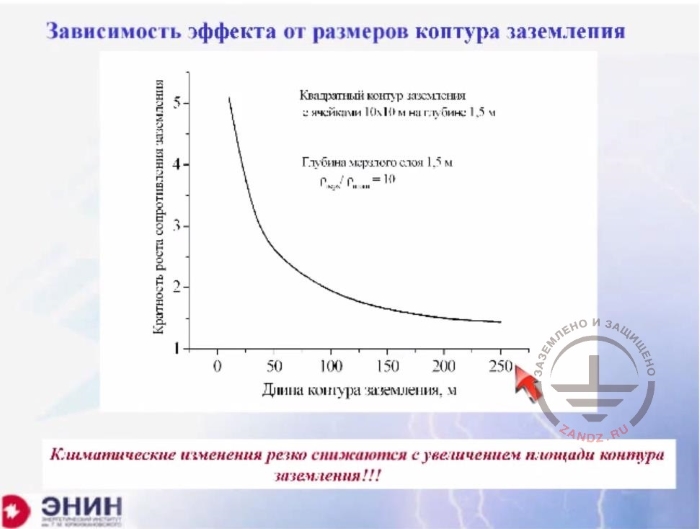
Зависимость эффекта от размеров контура заземления
|
Dependence between the performance and ground loop size
|
|
Кратность роста сопротивления заземления
|
Magnitude of grounding resistance increase
|
|
Квадратный контур заземления с 2 ячейками 10x10 м на глубине 1,5 м
|
Square ground loop with 2 cells 10x10 m at a depth of 1.5 m
|
|
Глубина мерзлого слоя
|
Frozen layer depth 1.5
|
|
Длина контура заземления
|
Ground loop depth
|
|
Климатические изменения резко…
|
Climate changes are decreased sharply with the increase of ground loop area!!!
|
And if I try to do the same thing for the ground loop, for example, 100 * 100 meters with mesh cages of 10 meters in size, then the impact will be even weaker. If the loop has a length of 100 meters, then a tenfold change in the grounding resistance leads only to a twofold change in the properties of the grounding device. Now look what happens if I take a mesh cage of 250 * 250 meters. This is roughly a mesh cage of a large substation. The tenfold change in the resistivity of frozen soil will change the resistance of the ground loop just by 1.5 times. I.e. if you have a large loop size, then the soil resistivity time variation due to the frozen or dry surface will not influence the effectiveness of the ground electrode system. There will be almost no effect. This is a very important factor we must bear in mind when analyzing what happens to your ground electrode system in a variety of climatic conditions.
Grounding resistance measuring
|
RU
|
EN
|
|
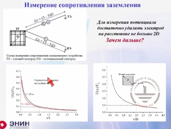
Измерение сопротивления заземления
|
Grounding resistance measurement
|
|
Схема измерения сопротивления заземляющего устройства…
|
Grounding device resistance measurement circuit
TЭ – current electrode ПЭ – potential electrode
|
|
Горизонтальная шина на глубине
|
Horizontal bus at a depth
|
|
Для измерения потенциала достаточно удалить электрод на расстояние не больше 2D
|
To measure the potential, it is enough to move electrode away to a distance of not more than 2D
|
|
Зачем дальше?
|
Why moving further?
|
|
Контур заземления
|
Ground loop
|
And now let's discuss perhaps one of the most serious issues. Ground resistance should be monitored. No one came up with a tool other than the ammeter and voltmeter for ground resistance monitoring. So you choose a ground loop which you need to measure. Then you drive an auxiliary current electrode into the soil and turn on the power supply. And now you have to measure the voltage on this ground electrode with respect to the grounding zero potential point. That is, with respect to an infinitely remote point. Divide the measured voltage by the current, and you'll get the grounding resistance. It's all simple, clear and understandable. There are many instruments that show your grounding resistance with directional arrow pointers or digital indicators. But there's an issue. How far do you need to move your potential electrode to assume that you've gone to the infinitely distant point? To do this, you need to track how the electrode potential changes with relation to the distance you move away from it. It is clear that this distance depends on the dimensions of the ground loop. For horizontal bus, the numbers listed here show the following. If you move away from the horizontal bus to a distance equal to its one length, then you'll come to a point where the potential differs about 10 times from the potential of the bus itself. I.e. you will not get zero, of course, but this will be 10% of the bus voltage. And such a distance equal to one length of the bus is enough for you to consider that you've reached the point of zero potential with 10% accuracy. Now let's take a square loop, for example, in the form of a mesh. Look, the potential decreases here. It decreases more slowly. But all the same, it is enough for you to move away 2 mesh diagonal sizes in order to reach the point where the potential is only 10% of the potential of the electrode you are measuring. This 10% error, in general, is quite acceptable. Nevertheless, the guidelines recommend you to move the electrodes away to a distance of three or even five sizes, not one or two.
The impact of current electrode
|
RU
|
EN
|
|
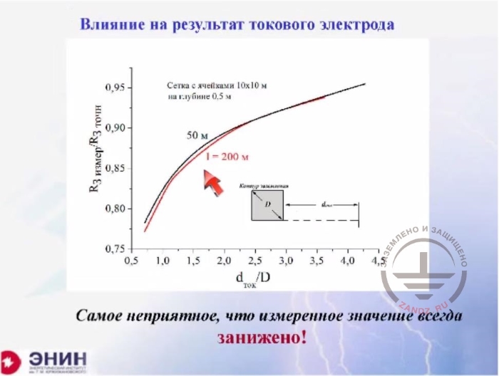
Влияние на результат токового электрода
|
Impact of current electrode
|
|
R3измер/R3точн
|
R3measur/R3exact
|
|
Сетка с ячейками 10х10 м на глубине 0,5 м
|
Mesh with cells 10x10 m at a depth of 0.5 m
|
|
Контур заземления
|
Ground loop
|
|
Самое неприятное…
|
The most troublesome thing is that the measurement is always undervalued!
|
| |
|
| |
|
In addition to an error associated with the fact that you are not at the point of zero potential but at the point with some finite potential, there is a second source of error. This second source of error is the current electrode. The current electrode contributes to the voltage distribution in the vicinity of the grounding device. And as the current does flow into the current electrode and flows off the measured electrode, this contribution into the potential will have a negative value. And as a result of the current electrode influence, you will underrate the potential of the measured loop. I.e. you'll get an error. And the error is bad in the sense that it reduces ground resistance value. Look, if you move away to a distance of one geometric size, this error will be in the range of 20%; if you move away by three geometrical sizes, then the error is only 5%, which is quite acceptable. And the requirement to move the current and potential electrodes away from each other by at least three sizes of the loop is a very unpleasant thing. If you have, for example, a ground loop of 100 x 100 meters in size, then its diagonal will be 140 meters. So you need to move one electrode from another to a distance of three diagonal sizes, which means you have to travel approximately 400 meters away from the loop in order to take measurements. Now try to do this in the area of urban development, and I'm afraid you will not succeed.
Eliminating an error caused by closely spaced electrodes
|
RU
|
EN
|
|
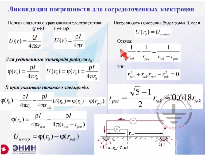
Ликвидация погрешности для сосредоточенных электродов
|
Eliminating an error caused by closely spaced electrodes
|
|
Полная аналогия с уравнениями электростатики
|
Full analogy with electrostatic equations
|
|
Для уединенного электрода радиуса r0:
|
For a stand-alone electrode with radius r0
|
|
В присутствии токового электрода:
|
In current electrode is present:
|
|
Погрешность измерения будет равна 0, если
|
Measurement error is 0 if
|
|
Откуда
|
Where
|
|
ИЛИ
|
OR
|
And then the following idea emerged. Can you compensate the measurement error related to the current electrode somehow? So the following thing was done. Look, here's the ground loop you are measuring. Here's your current electrode. The potential of this current and the potential of the opposite current will have different polarities. We make measurements on a straight line that connects the current electrode. This means there is a point somewhere where the potential is zero, and there is another point somewhere where the potential is negative. And if I connect a voltmeter between the measured electrode and the zero potential point, then I can compensate the error if I make the right connection. This solution was found for small-size electrodes, which could be identified as points. As a result of simple mathematical calculations shown on this slide, we obtain the following: if you install the potential electrode at this distance from the measured electrode, then you almost completely compensate the error associated with the location of the current electrode. This figure 0.618 of the current electrode location (you should drive the potential electrode into the soil at this distance) is included in many international guidelines on the measurement of ground resistance. And all you are proposed to do is putting the current electrode at a distance of, say, three geometric sizes, then measuring 62%, and driving the electrode potential into the soil. And then you are supposed to get a more or less accurate picture of the grounding resistance.
Electrodes on the same straight line
|
RU
|
EN
|
|
Электроды на одной прямой
|
Electrodes on the same straight line
|
| |
|
|
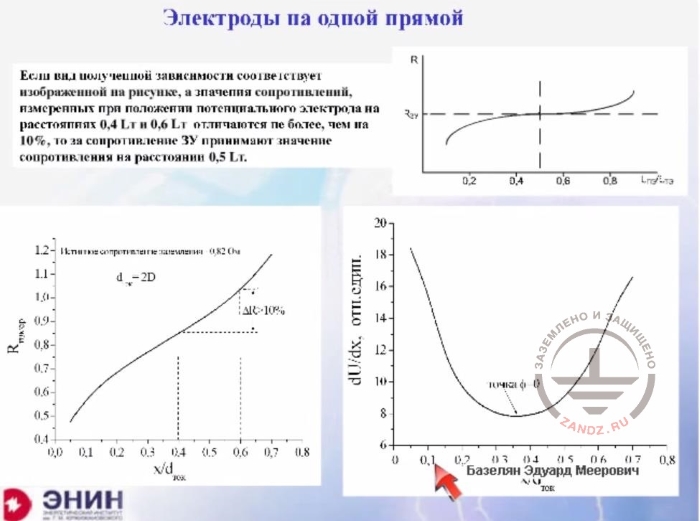
Если вид полученной зависимости соответствует…
|
If the representation of the resulting relationship is the same as on the picture, and the resistance values measured at the current electrode distance of 0.4L and 0.6L differ not more than by 10%, then the GD resistance takes a value of resistance at a distance of 0.5т.
|
|
Истинное сопротивление заземления 0,82 Ом
|
True grounding resistance 0.82 Ohm
|
|
dU/dx, Отн. един.
|
dU/dx, rel. units
|
|
Точка φ -0
|
Point φ-0
|
Why is it not included in the Russian guidelines? I would like to show you this. What do our methodical instructions say? They state the following. Let's assume that you put the current electrode at a distance of three geometric sizes of the loop you want to measure. Then you drive the electrode potential at a distance 10, 20, 30, 40 percent and so on. And then you measure the grounding resistance at these distances. Or you simply measure the voltage and build the relationship as shown on the slide. Here you have the position of the potential electrode, and these are the measurements you have obtained. If you obtain this kind of curve with a gently sloping tail, and your measurements differ by only 10% at 40 and 60% checkpoints, then you are recommended to take the mid-point and assume that the location of the potential electrode in the midpoint gives the true value of the grounding resistance. This is what's written in our manuals. I tried to make calculations for a variety of ground loops. I did this to see whether I can obtain that nice curve shown here. I wanted to see if the 60% and 40% checkpoints could differ by only 10%. You know, I went through a lot of various ground loops, and I couldn't obtain this result. The discrepancy was always more than 10% for important and complex systems of grounding devices. And then I started looking at the issue from a different angle. For what purpose it's all done? What do you build the curve for? And why do you need to seek the midpoint? It appears that the zero potential point is searched this way. But you can find the zero potential point very easily if you define the minimum value of the first order derivative. The words seem difficult, but in fact, "the first order derivative" boils down to the following. You just measure voltages between the first and the second point, then between the second and third point, then between the third and fourth point, and so on. Then you should find the least value, and this is the zero potential point, where you need to drive the potential electrode into. It is generally suitable for any situation, and not necessarily for a flatter curve which is shown in our guidance documents. But I'd like to talk about a different thing now. Let's discuss the following thing.
Measurement correction, mesh
|
RU
|
EN
|
|
Коррекция при измерениях
|
Measurement correction
|
|
R3измер/R3
|
R3measur/R3
|
|
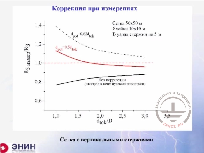
Сетка 50х50 м
|
Mesh 50х50 m
|
|
Ячейки 10х10 м
|
Cells 10х10 m
|
|
В узлах стержни по 5 м
|
Rods 5 m each in the nodes
|
|
Без коррекции (электрод в точке нулевого потенциала)
|
Without correction (electrode in a zero potential point)
|
|
Сетка с вертикальными стержнями
|
Mesh with vertical rods
|
Now, I'd like to explain what errors are caused by a recommendation in Western standards to put the potential electrode at a distance of 0.65 from the current electrode. You are expected to consider the point as a point with a zero potential. The error is shown on the slide. The dotted line at the top shows the error, which is obtained in the case when you use the Western methodology. So you've got the following error. If you are at a distance of approximately three maximum sizes, then you obtain an error within 10%. And this error skews the value upward compared to the true value. But if you start moving the current electrode closer, then your error begins to skew upwards very quickly. And at a distance of one geometrical size, you obtain an error up to 40%. So you get an overrated grounding resistance value. But if you use the Russian methodology, you also get an error but the value will be underrated in this case. You skew the resistance downward, and therefore this underrated value can be tolerated at the level of 10% when you put away your current electrode at a distance of three maximum sizes. But if you start to decrease this distance, your error begins growing very rapidly and at a distance about one geometric size, you obtain a downward bias of 20%. And then there comes a question. Maybe, you need to make measurements in a different way? For example, to search for a different distance to the current electrode and always obtain an admissible error? It turns out that such a position is very easy to find. You just have the following situation. If you put the potential electrode exactly midway between the current electrode and the electrode to be measured, then you get the error shown on the slide. It is almost zero at a distance up to two geometrical sizes. And if you put the current electrode at a distance of only one geometric size of the electrode to be measured, then the error does not exceed 10%. And it skews upward, which is not critical. But if you need to measure ground loops of larger sizes and there's no space to move further, then our Russian guidelines say that you have no other options than to calculate the resistance with such an error. But in reality, you do have another option. You can put the current electrode at a distance of one geometric size, just one. And then you drive the potential electrode in the soil exactly midway and get an error in the measured value of not more than 10%. Just feel the difference.
Measurement correction, the loop
|
RU
|
EN
|
|
Коррекция при измерениях
|
Measurement correction
|
|
R3измер/R3
|
R3measur/R3
|
|
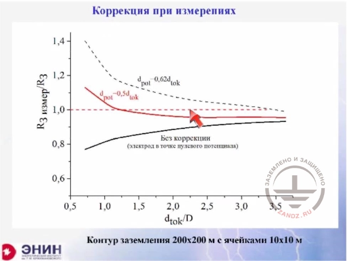
Без коррекции (электрод в точке нулевого потенциала)
|
Without correction (electrode in a zero potential point)
|
|
Контур заземления с ячейками…
|
Ground loop 200x200 m with cells 10x10 m
|
I've calculated this value for a large ground loop. The size is 200 * 200 meters, as shown on the slide. The red curve represents errors. I have a geometric size of only one size of the ground electrode system, and I obtain an error of less than 5%.
Measurement correction, horizontal bus
|
RU
|
EN
|
| |
|
|
R3измер/R3
|
R3measur/R3
|
|
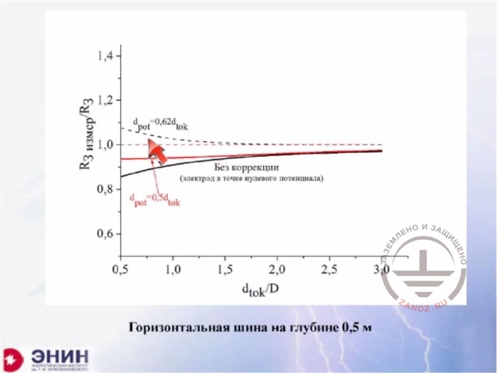
Без коррекции (электрод в точке нулевого потенциала)
|
Without correction (electrode in a zero potential point)
|
|
Горизонтальная шина на глубине 0,5 м
|
Horizontal bus at a depth of 0.5 m
|
Here I have single horizontal buses on the picture.
Measurement correction, vertical rod
|
RU
|
EN
|
|
R3измер/R3
|
R3measur/R3
|
|
Без коррекции (электрод в точке нулевого потенциала)
|
Without correction (electrode in a zero potential point)
|
|
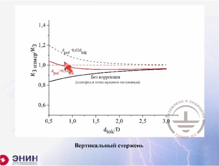
Вертикальный стержень
|
Vertical rod
|
And here I have single vertical electrodes. Whenever I put the potential electrode precisely midway I get a minimum error even at small distances between the current and grounding electrodes. This option, in my opinion, can make your life much easier. You can argue that this option is not described in the guidelines. No, it is not written there and I have never heard anything like this. But keep in mind that the guidelines are a recommendatory document. This is not a binding document. And in my opinion, if you are not able to use a free space in a densely built-up area, then do not hesitate to use this option. Put your electrode at a distance of only one geometric size and you'll get quite a decent value after placing the electrode potential right in the middle. That's all I wanted to say on this subject.
Galvanic link between ground electrode systems
|
RU
|
EN
|
|
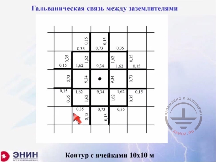
Гальваническая связь между заземлителями
|
Galvanic link between ground electrode systems
|
|
Контур с ячейками 10х10 м
|
Loop with cells 10x10m
|
Now, there's one more thing. One thing that bothers designers terribly. PUE says that all grounding devices are to be combined into a single ground loop whenever possible. This recommendation could be wonderful if it wasn't for the following ending: "provided that for technical reasons, the customer does not require you to arrange an individual ground loop". And designers hear the requirement very often. The designers say: we cannot work with the common ground loop as we need a separate the ground loop because we have the very sensitive equipment and we do not want to connect this equipment to the common loop under any circumstances. Or power engineers say: we have a large substation ground loop, here it is. A transformer house was built somewhere in this area. And the power engineers say: you cannot put a lightning rod on the transformer under any circumstances, as it will interfere with the transformer operation. Put the lightning rod to the ground and make its own ground loop. What do you need it for? You surely need to ask the customer this question. Why would you want an individual ground loop? And the customer's explanation is usually like this: I do not want the lightning current to come into the ground electrode system and affect the operation of my circuits. Let's reproduce such a situation at this slide. This is the substation ground loop. The mesh size is 10 x 10 meters. I put a ground electrode system loop in the middle. So where will the current go from this ground electrode system? It turns out that it will partly go to the nearby ground electrode system in any case. Look at these buses. A percentage of current that gets into this particular bus is shown here. Look at the picture: 40% of the current goes into the nearest bus. And the complete ground loop collects about 60% of the current. So you've made an individual ground loop, and what did you achieve? You achieved nothing for a simple reason that almost all the current was collected by the ground loop you were going to isolate.
The induced voltage in the loop 50x50 meters in size
|
RU
|
EN
|
|
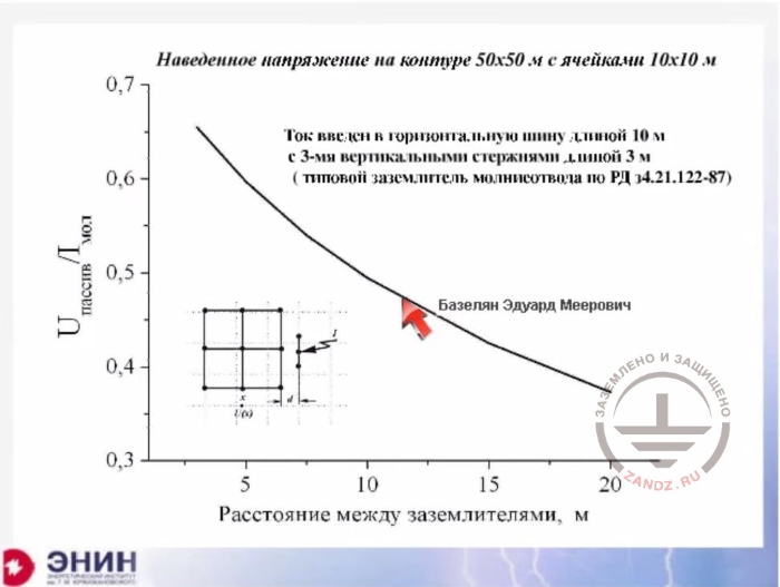
Наведенное напряжение на контуре…
|
Induced voltage in the loop 50x50 meters in size with cells 10x10m
|
|
Ток введен в горизонтальную ….
|
The current is introduced into a horizontal bus 10 m long with 3 vertical rods 3 m long (typical air terminal ground electrode system under RD 34.21.122-87
|
|
Uпассив/Iмол
|
Upassive/Ilight
|
|
Расстояние между заземлителями, м
|
Distance between ground electrode systems, m
|
Please look at the slide. Here I have the foundation of the building. The building has a foundation of 50 * 50 meters, and the building is explosive. This facility requires a separately installed lightning rod. And here is the ground loop of the lightning rod made in accordance with RD 34. I'll change the distance between the ground loop and the lightning rod and watch how the current comes into the ground electrode system of the building and what voltage will be registered in this ground electrode system.
|
 Lightning protection of residential and public buildings - answers to frequently asked questions in the design

 Lightning Protection of Large Territories: Parks, Grounds, Plant Territories. Page 1
 Lightning Protection of Large Territories: Parks, Grounds, Plant Territories. Page 2
 Lightning Protection of Large Territories: Parks, Grounds, Plant Territories. Page 3