Webinar #6 of Electric energy saving and quality improvement" series
Webinar text. Page 3
Fast navigation by slides:
Page 3:
11. Small-Sized Facilities
12. Earthing Standardization (1.2-1.4 Ohm)
13. Earthing of Oil Tanks
14. Permafrost
15. Conclusion
16. Questions and Answers
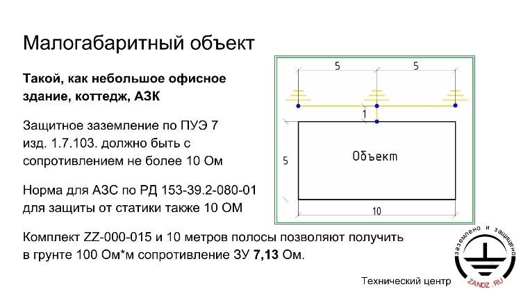
| Малогабаритный объект | Small facility |
| Такой, как небольшое офисное здание, коттедж, АЗК | Such a small office building, single-family home, gas station |
| Защитное заземление по ПУЭ 7 изд. 1.7.103. должно быть с сопротивлением не более 10 Ом | Protective grounding as per EIC Rev. 7 1.7.103 shall have the resistance of not to exceed 10 Ohm |
| Норма для АЗС по РД 153-39.2-080-01 для защиты от статики также 10 ОМ | According to RD 153-39.2-080-01 the standard value for the gas station protection against static discharge shall also be 10 Ohm |
| Объект | Facility |
| Комплект ZZ-000-015 и 10 метров полосы позволяют получить в грунте 100 Ом*м сопротивление ЗУ 7,13 Ом | Set ZZ-000-015 and 10 meters of strip allow to provide the ground terminal resistance of 7.13 Ohm at the soil resistivity of 100 Ohm*m |
| Технический центр | Technical center |
Small-Sized Facilities
— Small-sized facilities, such as office buildings, detached houses or petrol stations have the indicated dimensions of 5x10 m. They do not differ much in terms of the earthing system used: three 5-meter earth rods are driven at 5 meters from each other. In this case, the resistance is 10 Ohm, which meets the requirements for earth arrangements as specified in the Electrical Installation Code PUE 1.7.103. By the way, this value is also sufficient for gas stations. Rules of RD 153-39.2-080-01technical document also state that 10 Ohm is a standard value for protection against statistical electricity.
It means, that such an earthing system is arranged using a ZZ-000-015 earthing kit and a 10-meter connecting band. The given system resistance is 7.13 Ohms. You can install an additional loop to reduce it, as we discussed earlier on some previous slides.
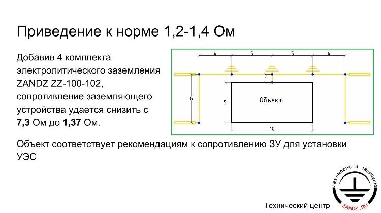
| Приведение к норме 1,2-1,4 Ом | Bringing to the standard of 1.2 - 1.4 Ohm |
| Добавив 4 комплекта электролитического заземления ZANDZ ZZ-100-102, сопротивление заземляющего устройства удается снизить с 7,3 Ом до 1,37 Ом | By adding 4 electrolytic grounding sets ZANDZ ZZ-100-102, the ground terminal resistance is reduced from 7.3 Ohm to 1.37 Ohm |
| Объект | Facility |
| Объект соответствует рекомендациям к сопротивлению ЗУ для установки УЭС | The facility complies with the recommendations in terms of the ground terminal resistance for ESH installation |
Earthing Standardization (1.2-1.4 Ohm)
— Such an option as using chemical earthing electrodes is also quite common. You can see 4 additional points here, where standard ZANDZ ZZ-100-102 rods (length: 2 and 4 meters, underground length: 0.6 meter) are installed. Installing just four rods reduces the earthing system resistance from 7.3 to 1.37 Ohms. This compact solution can bring the earthing system resistance to the standard recommended value for the efficient operation of the energy-saving hardware.
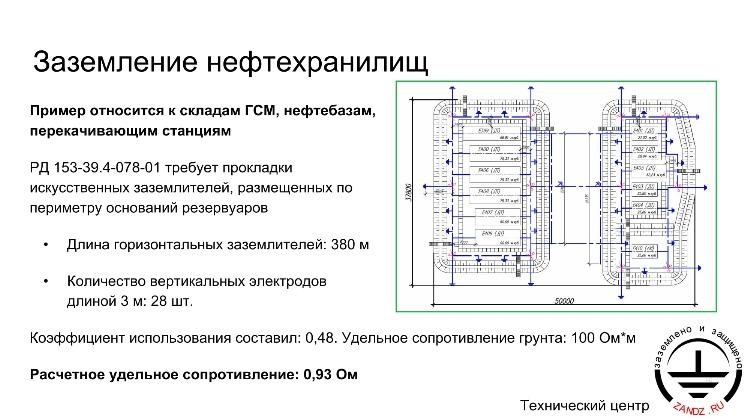
| Заземление нефтехранилищ | Oil storage farms grounding |
| Пример относится к складам ГСМ, нефтебазам, перекачивающим станциям | The example is related to the fuel and lubricants storage, oil tank farms, pumping stations |
| РД 153-39.4-078-01 требует прокладки искусственных заземлителей, размещенных по периметру оснований резервуаров | RD 153-39.4-078-01 requires laying of artificial ground terminals to be arranged by perimeter of the tank bases |
| Длина горизонтальных заземлителей: 380 м | Length of horizontal ground terminals: 380 m |
| Количество вертикальных электродов длиной 3 м: 28 шт. | Number of vertical electrodes with the length of 3 m: 28 pcs. |
| Коэффициент использования составил: 0,48. Удельное сопротивление грунта: 100 Ом*м | The utilization ratio was: 0.48. Soil resistivity: 100 Ohm*m |
| Расчетное удельное сопротивление: 0,93 Ом | Calculated resistivity: 0.93 Ohm |
Oil storage farms grounding
— Let's turn to earthing of oil tanks, including tank farms and pumping stations, which, pursuant to the operating standards, also require the installation of an earth loop and a two-point connection to it. When using surge protection rods, the current should spread in three directions, and the rods should be installed at 3-5 meters from each other in these directions.
This solution provides a fairly large area of the earthing system, despite the fact that the load factor is quite small: it equals to 0.48 in the soil with a resistivity of 100 Ohm*m. It ensures a good resistivity of 0.93 Ohm, which is quite sufficient for ESH operation. Oil terminals may vary in sizes, but the dimensions of the given oil tank meet the norms.
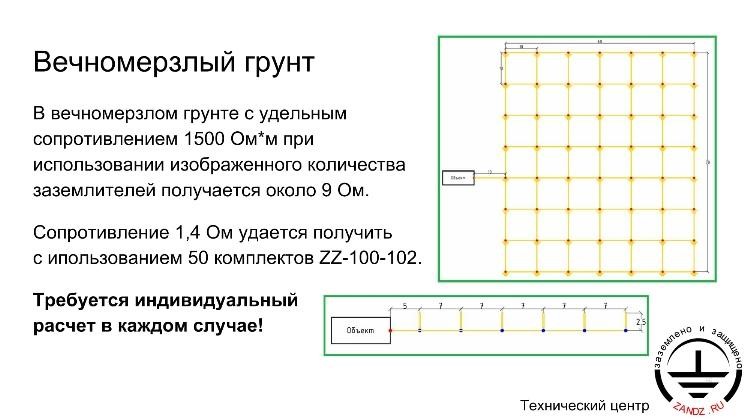
| Вечномерзлый грунт | Permafrost soil |
| В вечномерзлом грунте с удельным сопротивлением 1500 Ом*м при использовании изображенного количества заземлителей получается около 9 Ом | In permafrost soil with resistivity of 1500 Ohm*m the resistance is about 9 Ohm with the quantity of ground terminals as shown |
| Сопротивление 1,4 Ом удается получить с использованием 50 комплектов ZZ-100-102 | The resistance of 1.4 Ohm is achieved by using 50 sets ZZ-100-102 |
| Требуется индивидуальный расчет в каждом случае! | Each case shall be calculated individually! |
Permafrost soil
— Solutions for permafrost. The situation tends to get more complicated with permafrost, since its resistivity can reach 1500 Ohm*m or even more. Then the 9-ohm resistance will be sufficient for such a high value achieved in ordinary soil with a resistivity of 100 ohm*m. An earthing grid should be made using an earthing kit with a vertical earth rod at each intersection point. This standard earthing system ensures resistance of 9 Ohms. If you wish to use chemical electrode kits, you'll need 6 such kits to achieve the required 9 Ohms. To achieve 1.4 Ohms, you'll need 50 chemical electrode kits. Therefore, calculations should be made in each individual case for each individual soil with its own resistivity, which will determine whether the earthing system used is efficient enough to achieve the required efficiency of the energy-saving hardware installed in permafrost.
| Заключение | Conclusion |
| 1. Сопротивление заземления зависит от габаритов сооружения и принятых мероприятий по заземлению (использование ж/б фундамента, контура молниезащиты) | 1. The grounding resistance depends on the facility dimensions and the measures taken in relation with the grounding (use of reinforced concrete foundation, the lightning protection circuit) |
| 2. Низкое удельное сопротивление грунта облегчает достижение нормы 1,2-1,4 Ом | 2. Low soil resistivity provides easier achievement of standard of 1.2 - 1.4 Ohm |
| 3. Применение таких мер, как глубинное модульное и электролитическое заземление, позволяет снизить сопротивление ЗУ до необходимой нормы даже в вечномерзлом грунте | 3. Application of the measures like deep modular and electrolytic grounding allows the ground terminal resistance reduction down to the required standard even in the permafrost soil |
Conclusion
— Finally, I would like to summarize all the conclusions we came to in the course of the reasoning. Firstly, before arranging artificial earthing, one should consider the possibility of using the building foundation, since it can act as a low-resistance earthing system suitable for energy-saving hardware installation. If it fails to comply with the rules, then artificial earthing is arranged. The surge protection circuit can also immediately provide the required resistance values.
Soil with a low resistivity greatly simplifies the task, while permafrost or rocky soils with a huge resistivity value complicate the task and require a very complex solution that needs to be calculated. Besides, an earthing system should be installed based on the available area. Nevertheless, the use of measures such as chemical earthing systems or underground modular earthing can reduce the earthing system resistance to the required standard even when used in permafrost. That's all and thank you for watching. As I can see, some of you have asked questions in the chat window. I'm going to answer them now.
Igor Krivulets is asking: "Are there any limitations for earthing resistance when removing static electricity from the roof?"
— As far as I know, earthing resistance is not standardized, but you can always use a standard value of 10 Ohm, which is the same for a protective earthing system. You should always bear in mind the standard value of 10 Ohms.
— Vitaly commented: "One can't arrange an earthing system using a horizontal anode groundbed only. Vertically driven earth rods contribute greatly to the current distribution in the ground. Therefore, they should be driven in the ground below the freezing depth".
— I agree with you in part, because vertical earth rods can significantly reduce the resistivity (by 30% as we could see above), while the real example shows the value up to 100%.
Nevertheless, lightning protection system, which complies with the requirements of industrial standards for buildings larger than 900 m2, is made using a horizontal surge protection circuit without vertical electrodes. With smaller building dimensions, vertical earth rods are installed at the start points of down conductors.
— Vitaly commented: "In conditions of high soil resistivity, the earthing system should be designed in accordance with the effective touch voltage".
— That's quite right when we speak about substations with a voltage class from 110 kV or more and with a solidly earthed neutral. Then yes, it can be designed in accordance with the effective touch voltage. But to do this, you should comply with the standards established for this effective touch voltage value and use the necessary tools. Software is most often used to design a further system, when we take into account the relevant value of the effective touch voltage.
— Victor asked: " Hello. Why do you install lightning interception rods on brick air ducts on the roof in your projects? Isn't the earthing system too cost-ineffective when using a standard value of 10 Ohms and reducing the resistance to 0.93 Ohms? I think, it is reasonable for transformer substations only, but not for other facilities".
—
Yes, indeed, this issue should be considered with due account for all parameters, including the cost effectiveness of the earthing system, the costs of the energy-saving hardware installation and the future savings. In some cases, when the costs are quite large and the savings are not so significant, the earthing system is considered as cost-ineffective. It may meet the required standards with regards to protective and functional earthing, but be quite cost-ineffective in terms of the energy-saving hardware.
— Vitaly asked: “What is the purpose for reviewing earthing systems in a webinar?”
— We speak about earthing systems at our webinars for the purposes of effective functioning of all energy-saving equipment components. According to the research and measurement results, the earthing system must have a resistance of 1.2 – 1.4 Ohms for the maximum possible energy efficiency.
— Vitaly asked: “What do you think of active interception rods?”
— In fact, this question is outside the webinar scope, as the webinar is about earthing systems, and the question regards surge and lightning protection.
However, the Electrical Installations Code and regulatory documents restrict the installation, because when these documents were developed, interception rods were not used. If you design an earthing system pursuant to these documents, then you can install active interception rods, but make calculations in compliance with the protection zones as specified in the Electrical Installations Code and regulatory documents.
— Victor asked: “I've never seen the requirement to install the earth rod below the freezing depth. Where did you take it from? All that is required by regulatory documents is 0.7 m below the surface and allowance for the climatic coefficient. Unlike a water supply system or sewage system, an earth rod cannot break or tear when installed in the freezing zone, can it?"
— It is a horizontal groundbed that should be installed at 0.5 - 0.7 m below the surface, or even deeper depending on the circumstances. Regulatory documents do not limit the use of vertical earth rods to make the earthing system more compact. It will comply with all regulatory documents and will reflect the real conditions at the facility. Why not install vertical earth rods if we can? Besides, everything will be in compliance with regulatory documents. Any other questions?
— Alexander Ponomaryov asked: “Why is the linear circuit is used for vertical earth rod systems in almost all projects? In fact, earth rods are nothing more but a parallel connection of resistances. Will the resistance be lower if you use a closed loop of three elements?"
— Please see slide 5. I'll display the slide with the relevant formula.
The total earthing system resistance is calculated by the formula: the number of earth rods multiplied by the earth rod resistance. No matter whether vertical or horizontal electrodes are used, the result will be just like that. And, in general, it turns out to be the inverse of the total amount. That is, if we consider each individual vertical earth rod, then we must attach each vertical earth rod to the horizontal one. As a result, it turns out that the final impedance depends less on the number of connections and current distributions, but more on the total number of earth rods, i.e. the total number of horizontal and vertical earth electrodes. The bigger the number, the smaller the calculated value will be.
— Alexander Ponomaryov commented: “The calculated values do not always coincide with the practical ones”.
— Yes, I agree with you here, because it is not always possible to assess the soil resistivity, or to define the soil type, or to survey, especially to carry out a sounding survey in order to get more accurate values. And even if we have the required design basis, it is not always possible to calculate the earthing system resistance, since soils may have a large number of separate layers and differ in depth. For example, the top layer may consist of loam, the lower layer of rubble, and the lowest one may be represented by rocky soils. Prior to any calculations, complex reduction should be used here in accordance with two- or three-layer models. Such faults may cause discrepancies in practical calculated values, but you can't get rid of them, anyway. I hope, I've answered your question. I will post an email address to the chat in case you have any further questions. Please feel free to send any questions to my email address, and I'll do my best to answer them. Chat link: dkrasnoborov@skomplekt.com
— Victor asked: "If the average soil resistivity is measured at the design stage, will the loop resistance be close to the actual value?"
— In this case,
it is true when there is no distinct separation between the layers and a large difference between the probed points, since points may also have significant differences in the soil type and resistivity not only in layers, but along the horizontal plane as well. Averaging is bringing a number of values to one value. Faults are inevitable, but if the soil is approximately homogeneous within layers and between the points, then resistivity values may be reduced to an averaged value, which is rather close to the actual one. In this particular case the calculated value will coincide with the actual one. Victor, have I answered your question? I don’t see any more questions. Well, I added a link to the chat for you to ask questions.
— Victor asked: “Do you mean to say that to calculate the loop resistance one should complete geological survey and measure soil resistivity first?”
— Yes, that's right. Geological survey is a must if you wish to calculate the resistance value as accurately as possible.
— Alexander Ponomaryov asked: “In our area, the connection of three 1.8-meter vertical earth rods in a triangle with 1.5-meter sides results in 1.5 – 1.8 Ohms, but the projects suggest an installation of 6 rods in a line. I'm speaking about the Krasnodar region."
— Such a low value of 1.5 – 1.8 Ohms may depend on the fact that it was measured at the moment when the groundwater level rose very high. It may seem quite true. There can be such an explanation that the standard soil resistivity value is accepted as 100 Ohm * m in designs, but in fact, this same soil may have a much lower resistivity. And also depends on what rates are used in the design. As I can see, there are three vertical earth rods here, which means that it is most likely 10 Ohms. Well, all I can say is it's a very good soil.
— Alexander Ponomaryov commented: "Measurements were taken in all four seasons. The error is about 0.2 – 0.3 Ohm."
— This is not an error, but a regularity. Perhaps, the measurements were taken incorrectly, or, as I said earlier, the soil is quite good indeed. The error of 0.2 – 0.3 Ohms in all four seasons means a very good soil.
— Victor asked: "If the ground water has a low salt content, can it act as an aggressive environment during the current distribution (electrolysis)?"
— Yes, it may be aggressive, or it may may be acidic instead. Then it will also be aggressive to steel and to other materials. The moisture content may be about 80% in an acidic environment as well. Besides, an aggressive environment can be neither acidic nor alkaline, but a large moisture content can negatively affect earth rods.
— Victor commented: "I got it. Could you please say some more words about installing a surge protection rod on the air duct?”
— There may be different circumstances here, but in general, a rooftop ductwork rises above the roof. As you know, the highest point should be protected against lightening, and in our case the rooftop ductwork is the highest point. A lightning protection rod of the required height should be installed in accordance with the relevant protection zone.
— Victor asked: "But why on the brick one?"
— For the same reason as on the metal one.
The lightening strike may cause no damage to a brick pipe, but the further path of the lightning may be unpredictable. It means that, if a roof is not metal, but tiled, and cannot act as an earthing system, then a protective loop is installed along the roof perimeter. In this case the highest point is protected as well. In our case a pipe is the highest point. It is done to protect the house from lightning and unpredictable current spread, when the roof is made of natural materials. The current can spread either through the down conductors or without them. For example, down conductors are installed on the metal roof, which itself provides current spreading along the down conductors, but a roof made of natural materials cannot conduct electricity. It means that lightning protection measures are required, such as installing down conductors or installing a lightning protection rod on the pipe. This is the only way to protect private houses or apartment blocks.
— Victor asked: "Could you please tell us, how much they cost? Thank you".
— Their price may be different in each particular case, when the calculation results depend on loads, loops and circuits, the type of facility, and the currents available. They are pre-calculated according to the questionnaire filled in by the customer. The next stage includes an actual research with regards to the facility. Then the price is configured based on the customer's benefits. Thus, the price is configured as I've just said. Please feel free to send completed questionnaires for us to start the process. Then you'll know all the benefits and the price itself.
— There are no more questions left. Thank you for attention! Best regards and hope to see you at our next webinars.
<< Previous page
slides 6 – 10
Related Articles:
 Why Cannot Vertical Earthing Devices Be Installed Close to Each Other?
 Electrolytic Grounding in Permafrost Soils: Should Vertical of Horizontal Electrodes Be Used?