The twentieth webinar of "Earthing and Lightning Protection: Design Issues and Problems" series
Webinar text. Page 2 |
||
Interference in a shielded cable
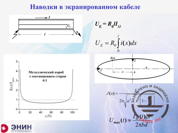
– Now let's discuss one more aspect. Very often, in the earth or even in the air, the shielded 220–380 V lines are used. Typical example: the lighting pole is installed that is used as a lightning arrester, and the lighting devices are hanging from it that illuminate the substation territory or service tracks or railroad, or something like that. In this case, the lightning current flows through the metal of this pole or through the metal of a special tube wherein the wires are laid, and it creates a voltage drop, again, according to the Ohm's law. The lightning current must be multiplied by the earthing resistance of such tube. If you do that, you will see that the tubes are usually made of steel and they are not very thick, the earthing resistance is several fractions of 1 Ohm, and the lightning may be up to 100 kA. Therefore, the surge in the internal conductor of the "thing" relative to the enclosure inside, may be about several kilovolts I have already mentioned. But the following situation is favorable: if you have got a bunch of conductors inside, the surge of each conductor in relation to the enclosure will exist, but the surge between the conductors will not. The phrase I have just said, which is a fake, is rather deeply embedded in the minds of many engineers and even good experts. But in reality, the situation is as follows: the surges between the conductors of this metal enclosure will not exist, but upon a single condition: if the enclosure has got a perfect circular and uniform thickness and is made of the same material. And if enclosure is not circular but elliptical as it is shown here, then the lightning current and its density depend on the curve radius of the enclosure. It has got one value here and another value there. The graph is provided below that shows how the current density varies along the enclosure length for the boxes having the rectangular cross-section. Here, we have got a rectangular box with the side length to width ratio of 4 : 1. Have a look at it please. The current density increases significantly in the corners. But if, in these corners, the buses will be installed, then between these two buses, a rather strong surge occurs. And for this reason, the use of circular enclosures is good, whereas the use of the enclosures having a different cross-section, such as rectangular, is not a very good choice. And you have to handle it with great caution. You have to perform special calculations for it, but we will address this issue in the next seminars.
Induced lightning interference
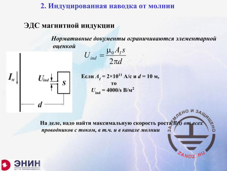
– Now, let's talk about the electromagnetic effect. It seems to be easy here. If the current flows along the conductor and it does not matter what kind of conductor it is. It may be a lightning channel or a lightning arrester, or even a current collector. It does not matter where the current flows but it matters what current flows. And this current creates an electromotive force of magnetic induction in any circuit, which is determined by the well-known formula of the school physics. If you look at the values here, you will obtain the following result. You have to consider that the lightning current may have an increase rate of 2*1011 A/s. In this case, at the distance of about 10 meters in the circuit of 1 meter, the electromotive force of magnetic induction will be 4 kV. It is a fatal electromotive force and, surely, you need to know how to struggle with it.
Electrostatic induction
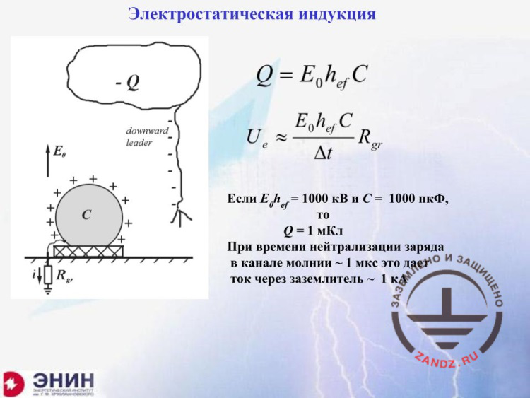
– There is one more type of induction, electrostatic. We do not know much about it, although it is very simple. You have got a facility. I have shown a fuel tank here. The lightning appears and it takes the electrical discharge with it. Such electrical discharge provides an opposite-sign charge on the facility. It is not a big deal because the lightning moves slowly with the speed of about 200–300 m/ms, and as a result, the discharges flow slowly from the earth, and they are located on the surface of the tank. Now, the lightning has reached the earth and struck it or the lightning arrester. It does not really matter, what. Now, the discharge disappears from the lightning channel because when it goes to the earth, it acquires the earth potential. But the discharge disappears rapidly during the major lightning stage. These are not milliseconds but microseconds. Due to the fact that such induced charge must return back to the earth through the earthing device during a very short time, the currents flowing through the earthing device become rather large; these are the kiloampere currents. And these kiloampere currents for the earthing resistance of about 10 Ohm cause the voltage drop of ten kilovolts in a facility that is very dangerous for the utilities, again.
Conventional protection means
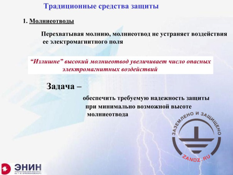
– If we are talking about the nature of electromagnetic effects, you understand that everything I have said can be disclosed in the book chapter having 20 pages at most. And now, the task that the designers and the experts face is as follows: how can I try to alleviate these problems without using SDPs, but using only conventional protection means instead? This is a critical issue. And I begin with the most simple point, the lightning arresters. What can we do with the lightning arresters? I repeat that the lightning arrester, when it takes the lightning strike, does not reduce its electromagnetic effect. What can a designer do?
Transition to the multielectrode system
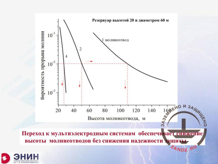
– And the designer may do the following: he has to provide the reliability of the facility protection against the direct lightning strike with the value specified in the customer's terms of reference. It can be done by means of lightning rods or a wire lightning arrester. A single lightning arrester may be used or ten of them. Question: what can we do to make the lightning arresters as low as possible and still provide the reliability we need? Because low lightning rod will not collect lightning strikes from the distance but high lightning arresters will do that. Do you need an example? In the Vostochny space port, two 150-meter lightning arresters are installed. They will collect at least about 2 strikes per year in the start position. And all electronics in the start position will be exposed to a dangerous surge at least two times a year. Can you reduce the lightning arrester’s height? Yes, you can. I am solving the following problem: I have got a tank 20 meters high and 60 meters in diameter. It is a huge fuel tank. I want to protect it using a single lightning rod. I want to provide the reliability of 0.99. It means that one lightning strike out of one hundred is allowed. Now, the lightning arrester’s height in this situation should be 110 meters. Then, I increase the number of lightning arresters: 2 lightning arresters of 50 meters, and 4 lightning arresters of 25 meters. I have gained the same effect using the lightning arresters that have got a height that is a quarter less. And this value may be reduced even more. What will it result in? It will result in that the number of dangerous electromagnetic effects to the entire automation equipment of this tank will be increased dramatically.
Wire advantages
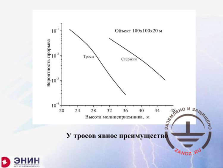
– But there is more to come. I have got a next step. And it is as follows. I had 4 lightning rods there. And now, what do I do? I put a wire system onto these 4 lightning rods, which delineates the external perimeter of the tank. Now, look at it. I needed a height of almost 40 meters for 4 lightning arresters for this facility. The facility here is 100 x 100 x 20 meters. And when I use wires, I use about 29 instead of 40 meters. Take into account that the number of lightning strikes is reduced proportionally to the square of height, and, therefore, the number of dangerous effects will be reduced 1.5-fold. But there is even more.
Crown shielding effect
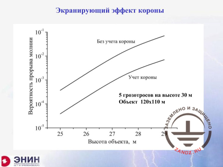
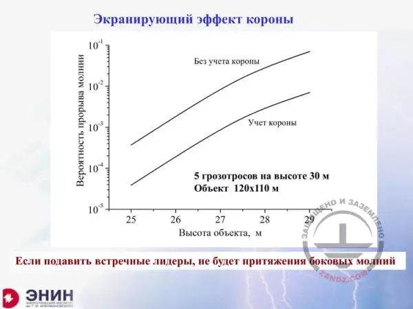
– If we use the wire lightning arresters, then I may excite the crown discharge from them. It will fill up the atmosphere above the protected system with the bulk charge, and it will increase the protection reliability through the shielding effect. Look at what we would have had without the crown and what we will have with it. The protection reliability is increasing without adding the lightning arrester’s height. This situation is the most important. When I choose a lightning arrester of the desired system, preferably wires instead of rods and multiple elements instead of single ones, I can significantly improve the protection efficiency while keeping low height of the lightning arresters.
Efficiency of wire lightning protection
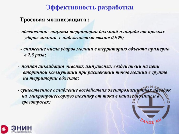
– Look at what we obtain according to our latest development. If I take the multi-wire system, i.e. the shielding wire system, the system reliability will be certainly not less than 0.999. It is difficult to say how many 9s will be there, because there is no such calculation reliability today, but it will be surely not less than 0.999. The number of strikes into the system that result in the electromagnetic interference will be reduced at least 2.5-fold or even 3-fold. This is the second point. And the third point is as follows. I can place the supports of the wire lightning arresters beyond the protected territory. Then, the current from the supports of the lightning arresters will not go into the facility’s earthing circuit, and there will be no interference. It is the third effect. Finally, there is the fourth effect. Certainly, the wires themselves will generate some electromagnetic field, but this field is much weaker that the one you would have had if you used the lightning rods.
Splitting lightning current among current collectors
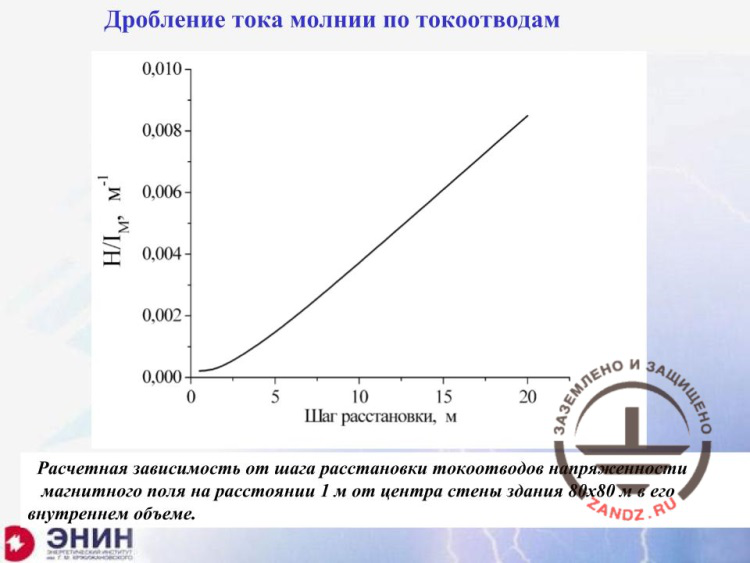
– I emphasize that this is about how the conventional lightning protection may be optimized by using multiple lightning arresters instead of single rods and wire arresters instead of lightning rods. And then, there is the second point: how can we pull the lightning current away? If the lightning strikes the facility, you can take the current away through the current collectors. Your task is to split this current among as many current collectors as possible. Here, I have got a step for current collectors. And there is the strength of the magnetic field inside the building at the distance of about 1 meter from its wall. If I use the conventional step of 10 meters specified in SO-153 as a minimum, then I will have this magnetic field. If I use the step of 2 meters, it will be like this. But you will ask me: "How can you find such an idiot who will install current collectors each two meters?" Surely, you cannot. But do not forget that instead of these current collectors you can use the conductive elements of the building: metal columns and reinforced concrete columns as they contain reinforcement. And the main point is to use the glass units reinforcement. Today, the exterior walls of many industrial and administrative buildings are made of glass units. Connect them from top to bottom, and each reinforcement of such glass unit will be a current collector. The lightning current will flow along them, and the electrical field within the building will decrease 10-fold or more. It means that the interference will also decrease.
Interference reduction graph
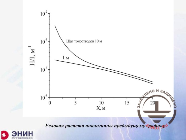
– There is one more point: I want to emphasize that this effect is not very strong, when you are immediately near the walls. This step is 10 meters, and this step is 1 meter, but the interference is reduced 100-fold. If you are far from the walls, there will be almost no effect, but there is also no interference at all. And the interference is reduced significantly near the walls, where the current collectors are nearby.
<< Previous page
slides from 1 to 10
Next page >>
slides from 21 to 30 + Questions and answers
Related Articles:


 Lightning Protection of Large Territories: Parks, Grounds, Plant Territories. Page 1
 Lightning Protection of Large Territories: Parks, Grounds, Plant Territories. Page 2
 Lightning Protection of Large Territories: Parks, Grounds, Plant Territories. Page 3


