The ZANDZ Technical Center made the calculation of lightning protection and grounding of the data processing center in Moscow. The peculiarity of the object was that it is located in an existing building, which previously had a different purpose.

A variant of lightning protection of the data center roof in the form of a mesh was agreed with the customer. The required resistance for the grounding of computing equipment, due to its large number, is determined up to 2 Ohms. To ensure this value, only one contour around the building was enough, which is also used to ground lightning protection.
Find out about data processing center lightning protection and grounding solutions from the news.
Task
Calculate lightning protection and grounding of a data processing center.
Solution
Calculations of lightning protection and grounding are made in accordance with the following documents:
- "Electric Installation Code" EIC 7th ed. (hereinafter - EIC).
- "Instructions for organization of lightning protection of buildings, structures and industrial communications" IS 153-34.21.122-2003 (hereinafter IS).
- "Instructions for lightning protection of buildings and structures" AD 34.21.122-87 (hereinafter - AD).
Lightning arresters are used for protection of structures from lightning strikes. A lightning arrester usually consists of a lightning rod, intercepting the lightning strike, a down conductor and a ground electrode. All these elements allow to safely drain the lightning current into the ground without a damage for the protected object.
A data processing center refers to traditional objects from the point of view of lightning protection in accordance with IS and to the third category of lightning protection in accordance with AD.
Description of the external lightning protection system and grounding of the data processing center
The set of measures to provide the required lightning protection is offered by the following solutions:
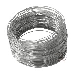
- Lightning protection of the object is made in the form of a lightning protection mesh with a mesh size of not more than 6x6 m from steel galvanized wire with a diameter of 8 mm. The mesh is designed so that the current has at least two different paths to the ground electrode.
- Down conductors are laid to ground conductors no less than 25 m along the perimeter of the building.
- Fixation of down conductors is performed (installation distance 0.6-1 m):
- on the sloping roof – with GL-11747A clamps;
- on the walls by means of GL-11703A clamps.
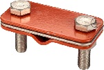
- To connect rolled metal over the length and in the mesh nodes, a universal clamp GL-11551A is used.
The set of measures on the provision of the necessary requirements to the grounding device is presented by the following solutions:
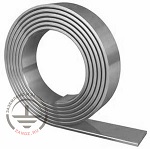
- Laying a horizontal contour around the data center building. The contour is made of corrosion-resistant copper-bonded stainless steel tape with the cross- section 4x30 mm, laying depth 0.5 m, distance to the wall of the building- at least 1 m.
- Every 6-12 m along the perimeter of the circuit, vertical electrodes of galvanized steel with a diameter of 16 mm and a length of 3 m are installed.
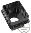
- At the four corners of the ground loop, inspection wells GL-11404 are provided.
- Connection of vertical and horizontal electrodes to each other is carried out using clamps ZZ-005-064. The number of clamps is taken with a margin for connecting the tape along the length.
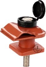
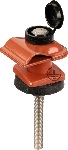
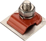
- The down conductor is connected to the galvanized tape protruding from the ground with the help of GL-11562M clamp.
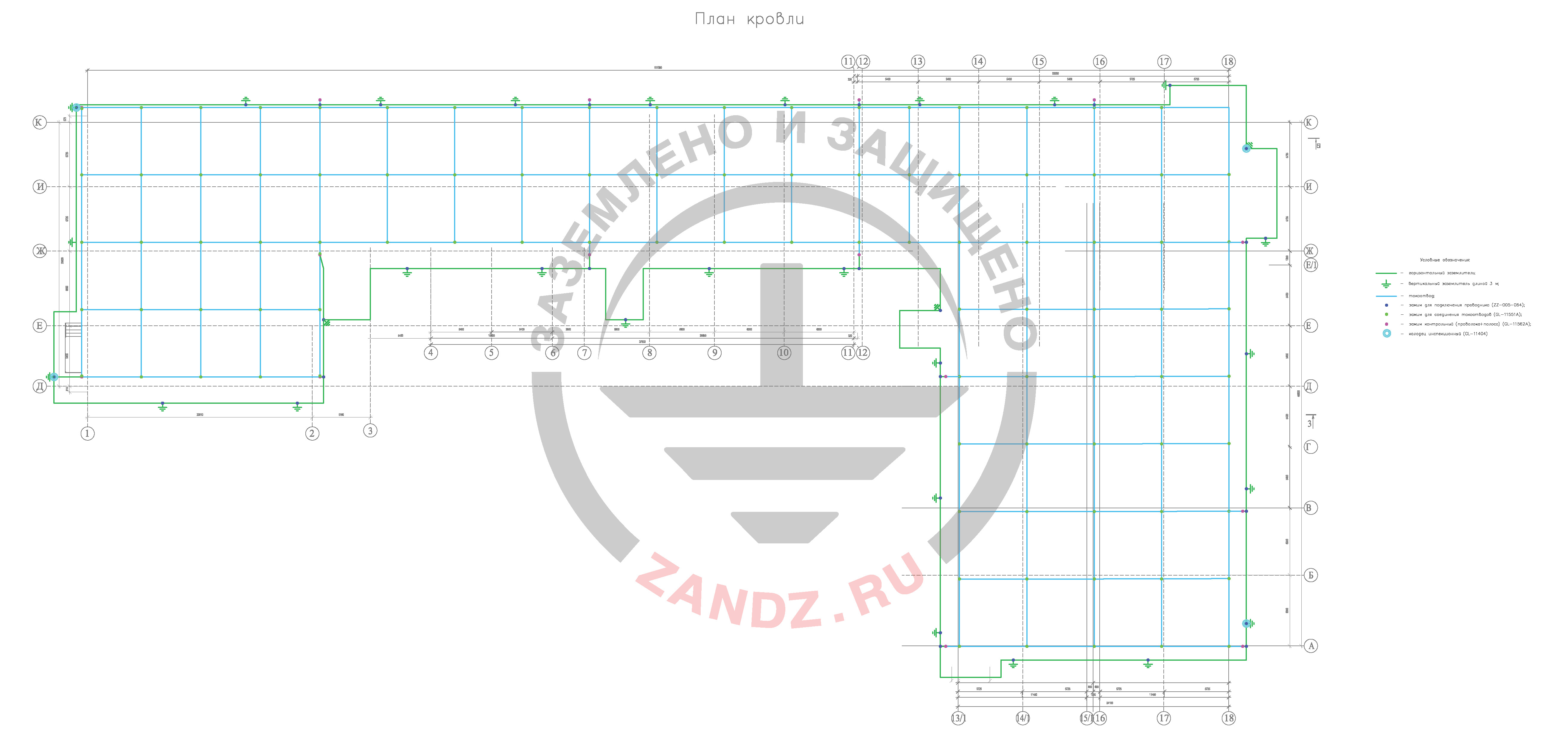
Figure 1. Plan with the layout of lightning protection elements and grounding device
Calculation of the grounding device resistance of a data processing center
Upon the request of the customer, the resistance of the grounding device must not exceed 2 ohms.
As the calculated value, the soil resistivity is 100 Ohm ∙ m
Warning. In case of a mistake or ground data limitation presented from the customer the given calculation of the grounding device is considered incorrect. In case of difference between the ground resistivity from the calculated grounding, it is necessary to carry out calculation with a real value. If the normalized resistance of the grounding device exceeds, it is necessary to introduce modifications into the structure.
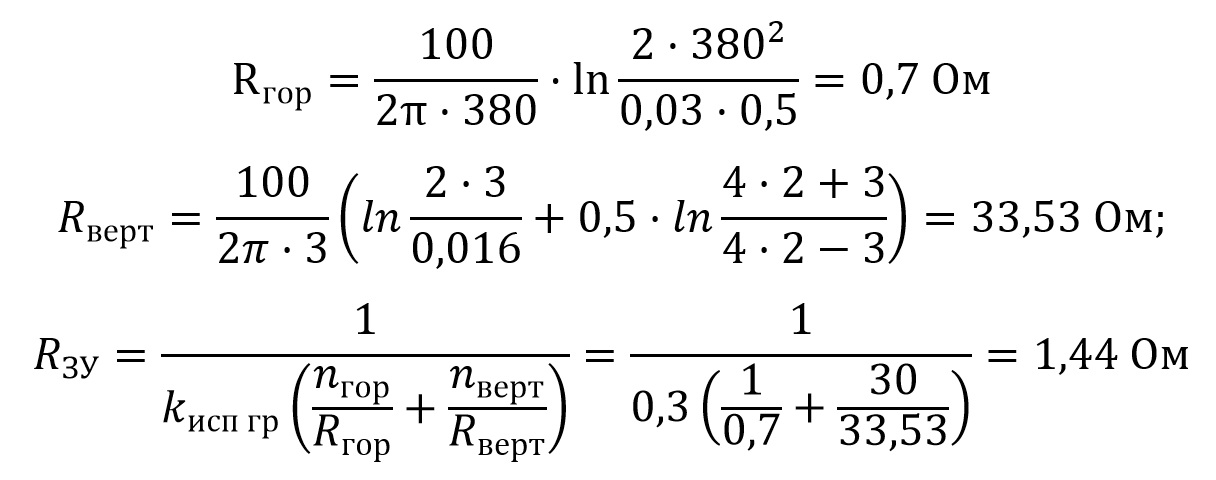
Calculation of the grounding device
The calculation is performed using software developed
OJSC “Energy Institute named after G.M. Krzhizhanovksy" (OJSC "ENIN").
Horizontal electrode resistance
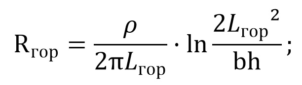
where p - soil resistivity, Ohm*m;
b - width of the horizontal electrode tape, m;
h - horizontal electrode laying depth, m;
L - horizontal electrode length, m.
Vertical electrode resistance
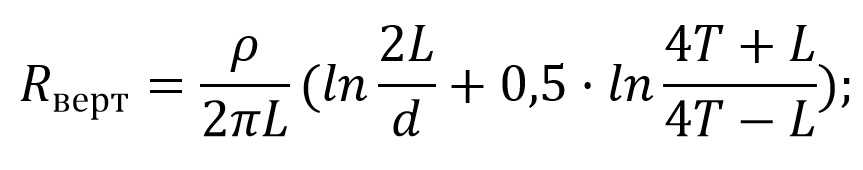
where p - soil resistivity, Ohm*m;
L - vertical electrode length, m;
d - vertical electrode diameter, m;
T - deepening - the distance from the ground surface to the ground electrode system, m;
T=L/2+t;
where t - is the depth of the electrode top, m.
Impedance of the grounding device
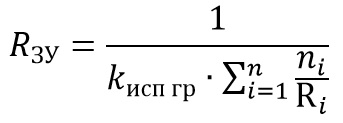
where n - number of kits;
kисп гр - utilization ratio.
Components for lightning protection and grounding of a data processing center
Table 1 - List of material needs


Do you have any questions on calculation of lightning protection for a data processing center? Please contact our ZANDZ Technical center!
See also: