Organization of grounding at substations with a high voltage of 110 kV and more is more difficult than at any other facility. Upon the request of EIC 7th ed., Paragraph 1.7.90, uch electrical installations having a source with an efficiently or grounded neutral must be equipped with a grounding device with a resistance of up to 0.5 Ohms.
To achieve such a low resistance, a grounding mesh is laid at the open distribution unit and on the territory within the enclosure. A huge amount of material - tape and round wire is spent on lateral and cross ground electrodes that form a mesh. In addition, vertical electrodes are installed near lightning rods, cable inlets into buildings, current and voltage transformers and surge arresters, which also reduce the grounding resistance of the substation. But even these measures may not be enough if the substation is located in permafrost and rocky soils.
In this case, modern technology comes to the rescue. The most effective of them is electrolytic grounding. This type of grounding is mounted on the free territory of the substation at a small distance from the foundations (approximately 3 m). There are options with horizontal and vertical electrolytic ground electrode systems. The first are intended for laying in a trench, and the second are mounted in a drilled well and can act as a vertical electrode that meets the requirements of the EIC. The exact number of electrolytic grounding conductors is determined by the calculation. But it is safe to say that about 30 vertical electrolytic ground electrodes with the length of 6 m each can reduce the grounding resistance from 3 ohms to 0.5 ohms even in permafrost ground.
To assess the benefits of electrolytic grounding, let's analyze two calculations for the same substation that ZANDZ Technical Center performed for one of the customers. In the first case, it was supposed to use galvanized steel mesh for grounding, in the second - electrolytic grounding.
Calculation of the grounding resistance of a substation using a metal mesh
In accordance with the EIC p. 1.7.90, for electrical installations with the voltage above 1 kV in networks with an effectively grounded neutral, the grounding device should have the resistance of not more than 0.5 Ohm at any time of the year, taking into account the resistance of natural and artificial grounding conductors.
The set of measures on the provision of the necessary requirements to the grounding device is presented by the following solutions:
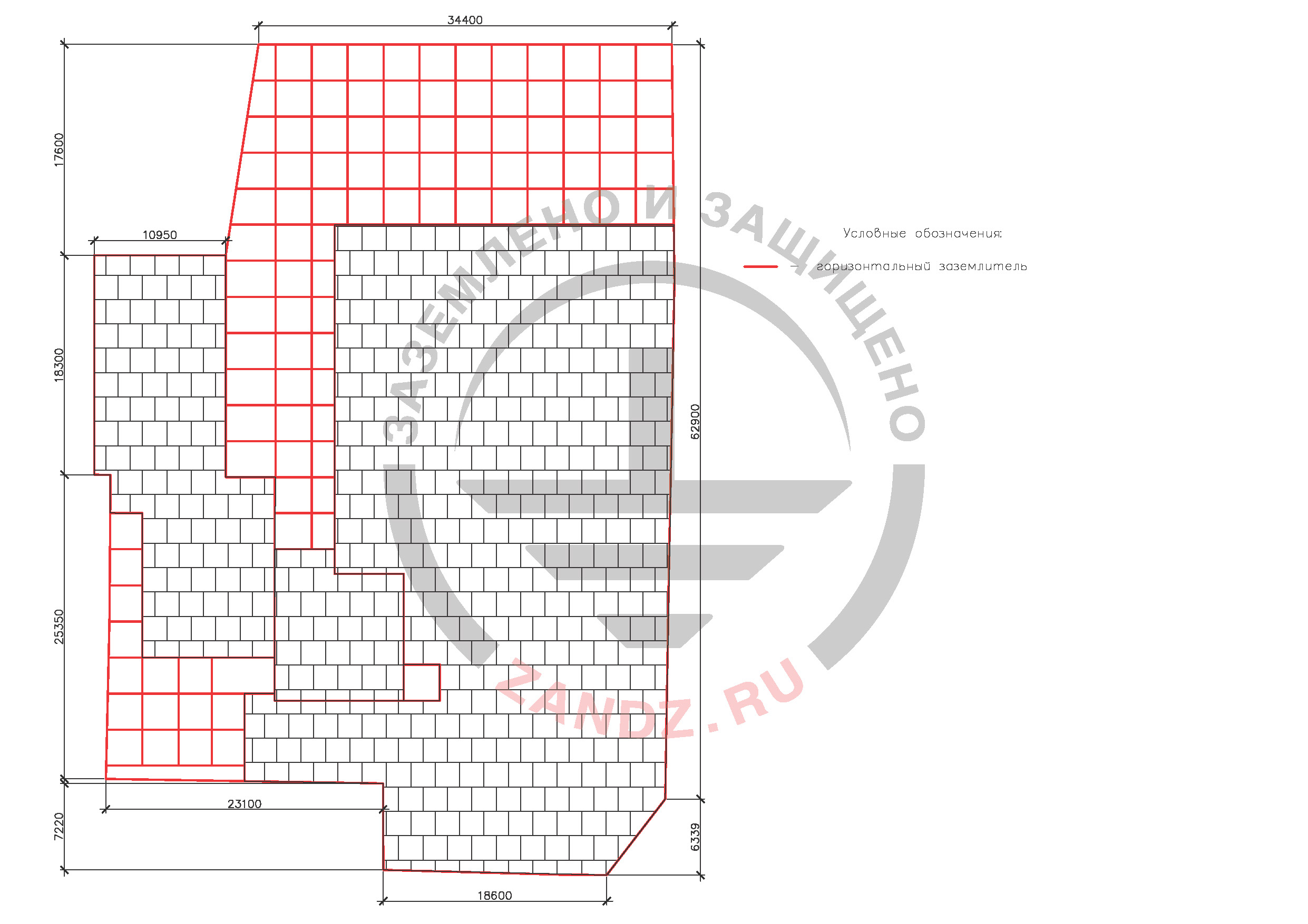
- on the territory of the substation, a mesh made of a corrosion-resistant galvanized steel tape with the cross section of 4x30 mm, laid at a depth of 0.5 m is carried out.
Calculation of the grounding device resistance for a substation
Soil data is accepted in accordance with the questionnaire completed by the customer.
Table 1 - Soils in accordance with the customer's questionnaireа
|
Interval in depth, m |
Accepted electrical resistivity, Ohm * m |
|
0,0 - 0,6 |
700 |
| below 0,6 | 190 |
Figure 1. Plan with a grounding device made of horizontal electrodes
Условные обозначения – Type Codes
Горизонтальный заземлитель – horizontal ground electrode
Calculation of equivalent ground resistivity for horizontal electrodes
The length of the horizontal ground electrode (diagonal) = 77 m;
Depth of the horizontal ground electrode = 0.5 m.
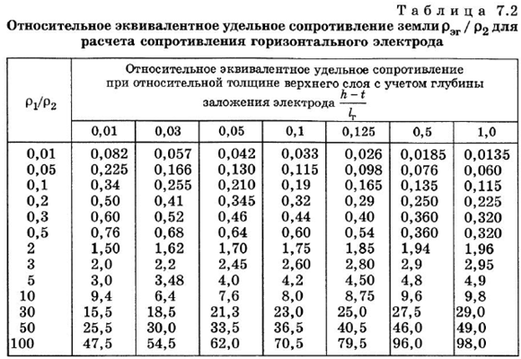
The equivalent value of the soil resistivity is calculated according to table 7.2 of the Mankov and Zagranichny guide “Protective grounding and bonding of electrical installations”.
Таблица 7.2- Table 7.2
Относительное эквивалентное сопротивление земли -Relative equivalent ground resistance
Для расчета сопротивления горизонтального электрода -To calculate the resistance of a horizontal electrode
Относительное эквивалентное сопротивление земли при относительной толщине верхнего слоя с учетом глубины заложения электрода - Relative equivalent ground resistance with a relative thickness of the upper layer, taking into account the depth of the electrode
Найдем необходимые величины:
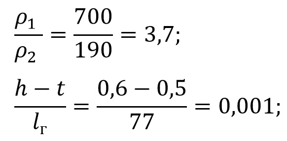
Let's find the required values:

Warning. In case of a mistake or ground data limitation presented from the customer the given calculation of the grounding device shall be considered incorrect. In case of difference between the ground resistivity from the calculated grounding, it is necessary to carry out calculation with a real value. If the normalized resistance of the grounding device exceeds, it is necessary to introduce modifications into the structure.
Grounding calculation was given with the help of software, developed by OJSC "Energy institute to the name of G.M. Krzhizhanovksy" (OJSC "ENIN").
Horizontal electrode resistance:

where pэкв гор equivalent soil resistivity for a horizontal electrode, Ohm · m;
b - width of the horizontal electrode tape, m;
h - horizontal electrode laying depth, m;
Lгорhorizontal electrode length, m.
Impedance of the grounding device:
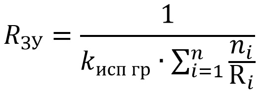
Where n - number of kits;
kисп гр - utilization ratio;
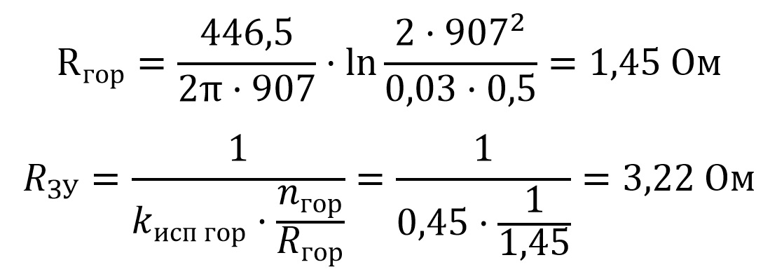
Calculation with the use of electrolytic grounding
Measures to bring the grounding resistance to the norm of 0.5 Ohms:
- to ensure the rated resistance of the substation grounding device, it is proposed to use эZANDZ ZZ-100-102-6MB electrolytic grounding;
- installation of 26 vertical sets of electrolytic grounding 6 m long ZANDZ ZZ-100-102-6MB is carried out;
- connection of ground electrodes and tape is carried out with the help of clamps ZZ-005-064;
- the kits are installed in parallel at the distance of 6 meters for an acceptable efficiency ratio and optimal electrolyte distribution in the ground.
Условные обозначения – Type Codes
Горизонтальный заземлитель – horizontal ground electrode
Комплект электролитического заземления – electrolytic grounding kit
Зажим для подключения проводника – Clamp for connecting conductor
Calculation of equivalent ground resistivity for vertical electrodes
where p1is the soil resistivity of the upper soil layer, Ohm · m;
p2 soil resistivity of the lower soil layer, Ohm · m;
h - capability of the upper soil layer, m;
L - deepening of the electrode, m;
t - depth of laying of horizontal electrodes, m;
k - is a dimensionless coefficient depending on the resistivity of the soil layers.
We calculate the equivalent soil resistivity of the three upper layers:
p1 = 700 Ohm · m;
p2 = 190 Ohm · m;
h = 0,6 m;
L = 6 m;
t = 0,5 m;
k = 1;


where C - is a non-dimensional factor describing the electrolyte content in the surrounding soil;
Lvert - ground electrode length, m
d - diameter of ground electrode, m;
pэкв верт - equivalent soil resistivity for a vertical electrode, Ohm · m.


Accessories for grounding of the substation
|
№ п/п |
Fig. |
Product item |
Product |
Quantity |
|
1. |
|
ZZ-100-102-6МВ |
26 |
|
| 2. |  |
ZZ-502-304-52 | ZANDZ steel copper-bonded tape (30*4 mm; coil of 52 m) | 18 |
|
3. |
|
ZZ-005-064 |
26 |
|
|
4. |
|
ZZ-007-030 |
9 |
Do you have questions about grounding of the substation in difficult soils? Please contact our ZANDZ Technical center for help!




.png)

