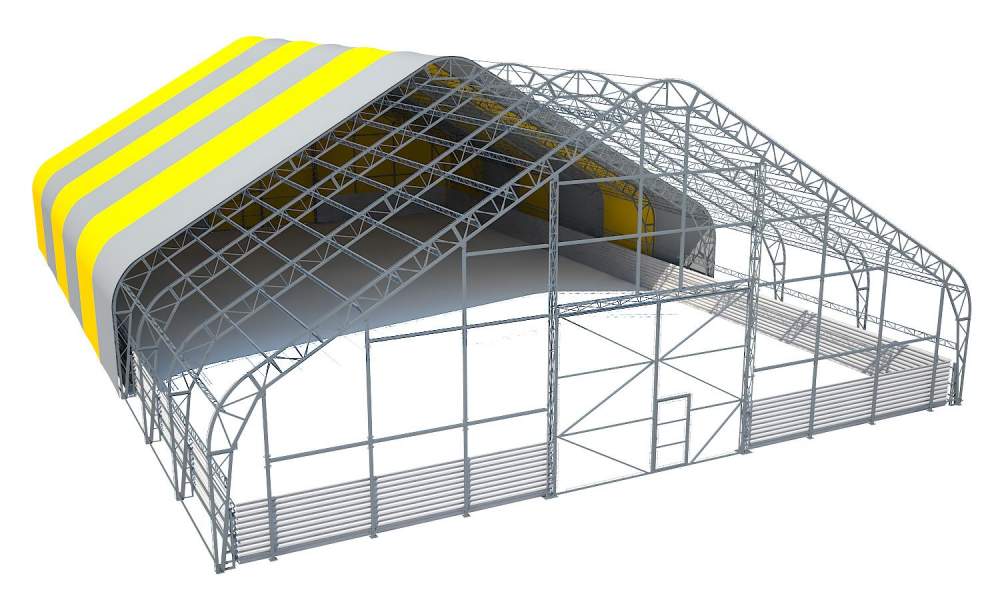
 There are several ways to protect an airplane shed and the material values that are stored in it from lightning. The first (and often the simplest) way is to use metal roof as a natural lightning rod and perform descents to the grounding device. Alas, this option is unacceptable in cases where, for example, there is an insufficient electrical connection between the metal structures or the roof is made of non-metallic material. Then another protection option is applied: installation of artificial lightning rods on the roof. This method was used by the ZANDZ Technical Center in one of its recent projects. We will study the solutuon we offered in detail.
Calculation of lightning protection of the airplane shed.
Object: airplane shed.

Figure 1 - Object plan.
Task: Perform calculations of lightning protection system for an airplane shed
Protection of buildings and structures against lightning discharges is ensured by lightning rods. A lightning rod is a device rising above the facility that diverts lightning current into the ground without entering the facility. It consists of a lightning rod which directly takes the lightning discharge upon itself, a down conductor and a ground electrode.
Solutions to meet the requirements for a lightning protection system of the airplane shed:
1. Lightning protection is carried out in accordance with EIC 7th edition., IS 153-34.21.122-2003 "Instructions for lightning protection of buildings, structures and industrial communications" (hereinafter IS) and AD 34.21.122-87 "Instructions for lightning protection of buildings and structures" (hereinafter AD).
2. The object refers to category 3 of lightning protection. System reliability must be not less than 0,9.
3. Lightning protection of the object is made using 2 vertical lightning rods 7 m high on the wall (ZZ-201-007-3);
4. All metal structures and communications on the roof must be connected to down conductors.
5. Laying of horizontal ground electrode around the building. The ground electrode is made of corrosion-resistant stainless copper-bonded steel tape with the cross- section of 4x30 mm (GL-11075), laying depth 0.5 m, distance to the wall of the building 1 m.
6. In the places of lowering the down conductors, 4 vertical electrodes (copper-bonded rods with a diameter of 14 mm.) 3 m long are being installed.
7. The connection of the vertical and horizontal electrodes to each other is carried out using clamps ZZ-005-064. The number of clamps is taken with a margin for connecting the tape along the length.
8. The down conductor is connected to the copper-bonded tape protruding from the ground with the help of GL-11562A clamp.
9. In case of presence of the existing grounding device, they should be united into one grounding device in accordance with EIC p.1.7.55.
Results of the calculation carried out with the software developed by the OJSC "Energy Institute to the name of G.M. Krzhizhanovsky (JSC "ENIN"):
Density of lightning strikes into the ground - 4 strikes / sq. km per year;
The total number of strikes into the system is - 0.036 (once in 28 years);
The total number of breakthroughs is 0.0021 (every 76 years);
The reliability of the system is 0.942;
Probability of a breakthrough into all the system objects - 0.058.
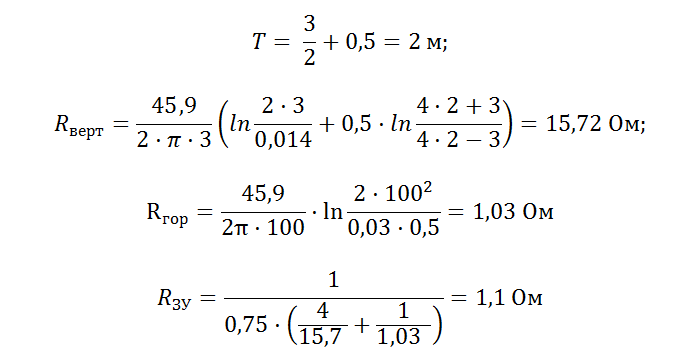
Grounding device resistance calculation:

The design resistance of the grounding device is 1,1 Ohm.
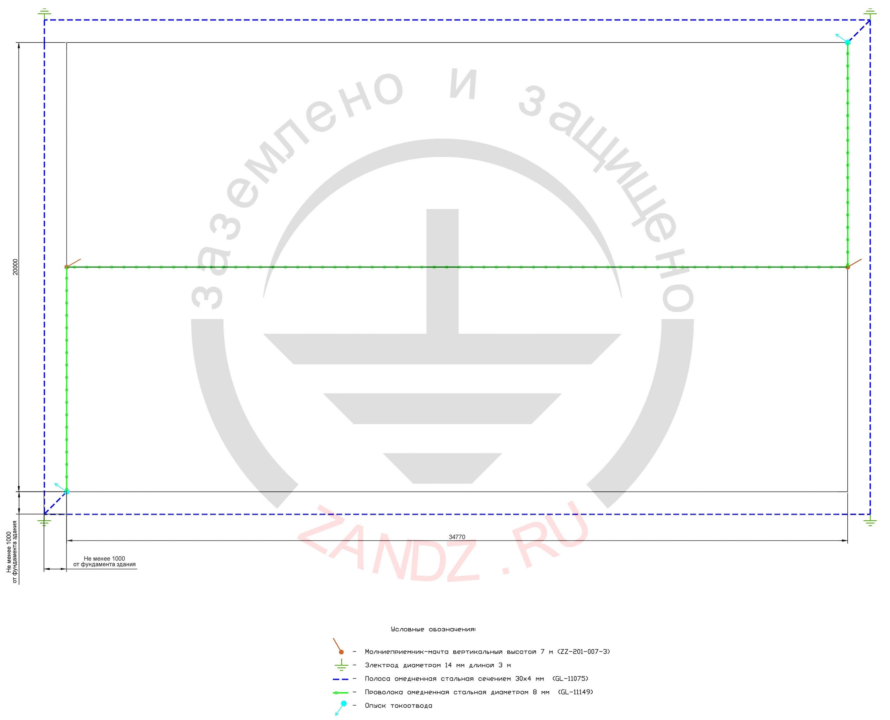
Figure 2 shows the arrangement of equipment.
Table 1 gives the list of the required equipment and materials.
Figure 2 - Location of equipment for lightning protection of the hangar.
Условные обоначения – Type Codes
Молниеприемник мачта высотой 7 м – Air –terminal mast 7 m high
Полоса омедненная стальная сечением 30*4 мм – Copper-bonded steel tape with the cross section of 30* 4 mm
Проволока омедненная стальая диаметром 8 мм – Copper-bonded steel wire with the diameter of 8 mm
Опуск токоотвода – Down conductor downdrop
Table 1 - List of need in materials.
Related Articles:


