Sometimes for reliable grounding it is not necessary to use vertical grounding electrodes in the form of ground pins / rods. Ground strip is enough. Let's take a closer look at a real example!
In this August we received a request for grounding design calculation for a public institution in Novokuznetsk. Our technical experts reviewed the source data and set to work:
1. Facility
Two-storey building with an area of 1.600 sq.m. and a height of 9 meters. Roof is pitched, layered, covered with slate.
Ground: asphalt overlay, bottom layer - loam with specific resistance of 500 Ohm per meter.
2. Task:
To calculate the system of lightning protection and grounding.
3. Solution:
The activities were carried out in accordance with the following documents:
From the point of view of lightning protection according to the CO instructions this building is “usual”. According to the RD building is of the 3rd category (more on the classification of facilities). . Protection of buildings from lightning strikes is carried out by the lightning grid. According to the paragraph 1.7.103 of the EIC. the total dissipation resistance of grounding conductors (including natural ones) of all re-groundings of the PEN-conductor of each air line at any time of the year should be max. 10 Ohms with linear voltage of 380 V for a three-phase current source or 220 V for a single-phase current source.
Detailed description of the lightning protection arrangement:
Lightning grid and current leads with copper-coated wire with the diameter of 8 mm. Raise the current lead by 1 meter in the grid nodes. Mesh step should be max. 10 meters. The equipment location is shown in Figure 1. Connect all metal objects / structures / pipes / antennas on the roof to the lightning grid.
According to the paragraph 2.26 of the RD when a grid or metal roof is used as a lightning rod, an external contour consisting of horizontal electrodes should be laid in the ground at a depth of at least 0.5 meters underground. Installation of vertical electrodes is not required since the area of the building is more than 900 sq. meters. The distance from the foundation to the contour is at least 1 meter. Connect the grounding device to the input equipment using the grounding conductor in PVC insulation of ZZ-500-110 wire.
Calculation of the resistance of the grounding device:
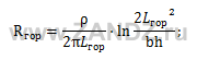
где p - specific resistance of the ground, Ohm per meter;
 b - horizontal electrode strip width, m;
 h - horizontal grid depth, m;
 Lгор - horizontal electrode length, m.
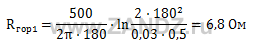
The design resistance of the grounding device is 6.8 Ohms
that is less than the permissible resistance of 10 Ohms.
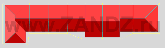
Figure 1. The lightning protection and grounding equipment location. Top view
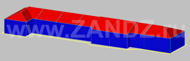
Figure 1.1. The lightning protection and grounding equipment location. Side view
The list of necessary materials is given in table 1.
|
№ п/п |
Fig. |
Article |
Product |
Quantity, piece |
|
1 |
|
GL-11149-50 |
GALMAR Copperplated wire (D 8 mm / S 50 mm²; coil 50 meters) |
13 |
|
2 |
|
GL-11551A |
GALMAR Clamp for connecting shunts (painted galvanized steel) |
60 |
|
3 |
|
GL-11747A |
500 |
|
|
4 |
|
GL-11703A |
GALMAR Clamp to the facade for the shunt (painted galvanized steel) |
150 |
|
5 |
|
GL-11562A |
GALMAR Test clamp for connecting the "wire + strip" shunts (painted galvanized steel) |
20 |
|
6 |
|
ZZ-005-064 |
30 |
|
|
7 |
|
GL-11075-50 |
GALMAR Copper-coated strip (30*4 mm / S 120 sq. mm; coil 50 meters) |
5 |
|
8 |
|
ZZ-500-110 |
ZANDZ Grounding Conductor (10m; S25; solid; with bolt cap D8) |
1 |


The solution described in this example will provide a reliable external lightning protection and grounding system for the building.
Order a free consultation and calculation of grounding and lightning protection systems for your facility! Our technical experts will be glad to help you!