27.10.16
The roofs of many buildings are topped with spires. We can see them on towers, cathedrals, chapels, cultural and administrative buildings. Spires have symbolic meaning or are simply decorative, but in any case they are natural lightning receivers as the highest point of a structure. Unfortunately, the requirements they must fulfill as elements of lightning protection are not always satisfied during construction.
Architects and builders may not take account of the need to protect against lightning and may use inappropriate materials. When trying to make a spire even higher to give the building a more impressive appearance, it is not always taken into account that the higher the spire, the more often lightning will hit it. In this and all other cases it is extremely important to use the right materials, of the right thickness and cross-section.

We will tell you about a railway station that has spires on its roof. At first glance, the layout makes them ideal lightning receivers. But if you look closer, it turns out that they are not high enough to ensure adequate protection for the building, and the materials do not meet standards. Therefore, to comply with all requirements, the ZANDZ technical center drew up recommendations for the modernization of lightning protection systems at the station. Let's look at this example.
Sample calculation.
The object of lightning protection and earthing installation is the railway station.
The arrangements were carried out in accordance with the EIC 7th ed. Chapter 1.7, IS 153-34.21.122-2003 "Instructions for the lightning protection of buildings, structures and industrial communications" (hereinafter IS) and AD 34.21.122-87 "Instructions for the lightning protection of buildings and structures" (hereinafter AD).
The building being protected is an ordinary structure in terms of lightning protection as per the IS and is in Category 3 according to the AD.
Buildings are protected against lightning strikes by lightning rods. A lightning rod is a device rising above the facility that diverts the lightning current into the ground without entering the facility. It consists of a lightning rod that directly receives the lightning discharge, a conductor cable and the earthing electrode system.
Lightning protection with the existing spikes

Figure 1 - Protection zone formed by existing building elements
As can be seen in Figure 1, the zones from the existing spikes do not fully cover the building. They need to be replaced with higher lightning receivers.
Required arrangements for lightning protection
The action plan to ensure compliance with the necessary requirements for a lightning protection system is as follows:
- Installation of three 4 m high lightning rods and four 2 m, with 0.5 m of the length of the rods used for fastening. Thus, the elevation will be 3.5 m and 1.5 m, respectively;
- two lightning rods at the edges need to be replaced. If the middle spire and the four lightning receivers in the middle part do not comply with the regulatory requirements as per GOST R IEC 62561.2-2014, they also need to be replaced;
- The lightning rods are interconnected to make two conductor cables using copper-plated wire (D = 8 mm) from each lightning rod. The conductor wires are connected to the artificial ground conductor. The conductor cables are mounted as follows (installed 0.6-1 m apart):
- to drainpipes – with GL-11514 Clamps;
- to the wall – with GL-11703A Clamps;
- on the roof – with GL-11747A Clamps;
- conductor cables are connected and branched with GL-11551A Clamps.
Earthing device
The action plan to ensure compliance with the necessary requirements for the earthing device is as follows:
- installation of the grounding device, consisting of 4 vertical electrodes (copper-plated rods 14 mm in diameter), 3 m long, joined by a horizontal electrode (copper-plated tape 4x30 mm). The distance between the vertical electrodes is at least 5 meters, with the distance from the horizontal electrode to the building walls being 1 m and the depth 0.5 m;
- vertical and horizontal electrodes are connected with a ZZ-005-064 clamps;
- the conductor cable is connected with the copper-plated tape termination from the ground with a GL-11562A control clamp.
The layout of elements in the lightning protection system and the earthing device is shown in Figure 2. The protection zone for the lightning rods corresponding to the zone B of the AD is shown in Figure 3.
Figure 2 – A sketch with the layout of lightning protection elements and the grounding device

Figure 3 - Protection zone

Table 1. List of required materials


Internal lightning protection (SPD)
To protect equipment and power utilities inside the building, we recommend a serious of measures to rule out the impact of hazardous overvoltages.
Protection of the electrical system. Protection in the main distribution panel
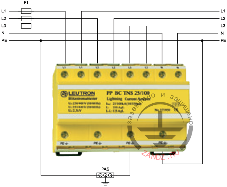
The surge protection device (SPD) in the I+II+III PP BCВ TNS 25/100 class is installed in the distribution panel; this was chosen due to the three-phase input to the house and the TN-C-S or TN-S power system
The connection is made in series (V-connection). We recommend using standard F1 fuses (see the diagram) at a nominal rating of up to 125A.
If a local switch (or protective fuses instead of it) designed to withstand mains power is installed and its nominal rating is less than 125 A, then additional F1 fuses are not required.
SPD connecton diagram is shown in Figure 4.
Figure 4 - SPD connection diagram
|
№ |
Photo |
Product item |
Name |
Quantity, pcs. |
|
1.
|
 |
LE-373-960 |
1 |
Lightning protection of the facility is considered incomplete without the stated measures, because only the use of protective devices makes it possible to reduce overvoltages in the mains to a level safe for equipment.
If you have any questions about the lightning protection of buildings with spires and other natural lightning receivers, please contact the ZANDZ Technical Center!
See also:
- Design of earthing and lightning protection
- Real-life calculations of earthing and lightning protection
- Modular earthing