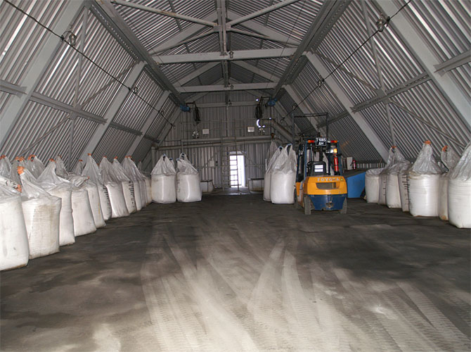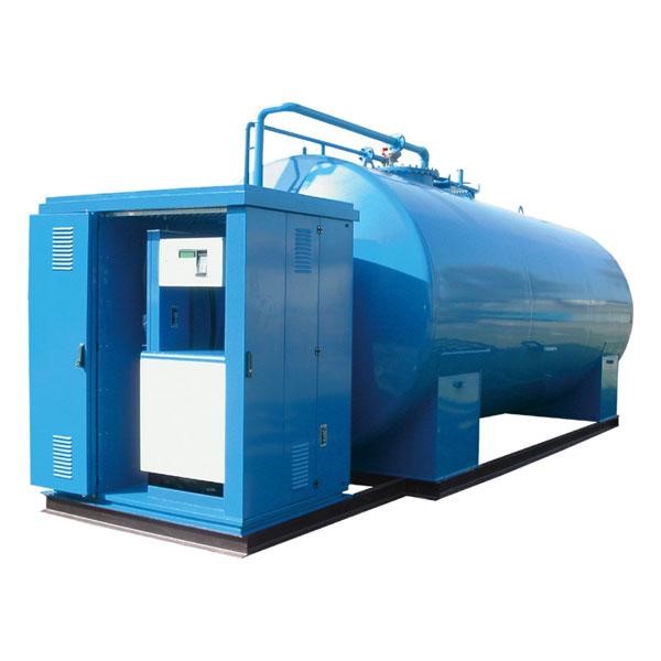
Explosive facilities such as fuel stations require special safety measures. One of the most important measures to prevent accidents is lightning protection for fuel storage and filling.
The absence of the lightning protection or its incorrect performance may lead to some very serious consequences including station ignition, tank explosions, power supply issues and damage to other electronic devices.
The ZANDZ Technical Center has received a request to calculate the lightning protection and grounding for a fuel station. Let's consider the proposed solution.
Lightning protection calculation
The activities were made in accordance with the Electrical Installations Code (EIC), Rev. 7, Chapter 1.7, SO 153-34.21.122-2003 "Guidelines for Arrangement of Lightning Protection of Buildings, Structures, and Industrial Utilities" (hereinafter referred to as SO), and RD 34.21.122-87 "Guidelines for Arrangement of Lightning Protection of Buildings and Structures" (hereinafter referred to as RD).
The facility is classified as Category 2 according to RD. The reliability of the system should be no less than 0.95.
The protection zone calculation according to SO:
Lightning rod:

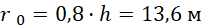
м - m
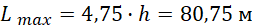
Cone height according to SO, Table 3.4:
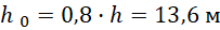
Cone radius according to SO, Table 3.4:
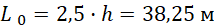
Distance between the lightning rods:

The limit distance between lightning rods according to SP, Table 3.6:
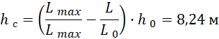
Sagging height:
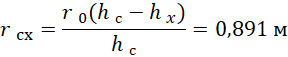
To provide the protection zone of the desired reliability, horizontal section radius  at the height
 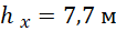 is determined as:
Lightning protection performance
Protection of buildings against lightning strikes is provided by using lightning arresters. Lightning arrester is a device that is elevated over the protected facility through which the lightning current goes into the ground bypassing the protected facility. It consists of a lightning rod that directly accepts the discharge of a lightning , a current collector, and a ground terminal.
To choose the lightning rod type, in addition to the height, climatic data for the installation region should be considered, such as wind and snow regions. Incorrectly calculated operational parameters may be a reason of the lightning rod fall; therefore, they should be considered.
The facility lightning protection is made using 4 separate standalone lightning rods 17 m high, ZZ-201-017-В4-Сн3.
Ground terminal resistance calculation:
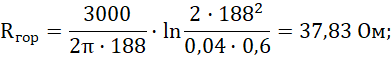
The estimated soil resistivity is taken to be 3000 Ohm ∙ m.
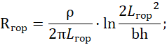
Horizontal electrode resistance:
Гор - Hor
where  – is soil resistivity, Ohm·m
 is bar width of a horizontal electrode, m;
 - is depth of the horizontal electrode, m;
 –is length of the horizontal electrode, m.
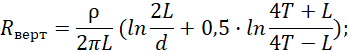
Vertical electrode resistance
Верт - vert
where – is soil resistivity, Ohm·m;
 – is length of the vertical electrode, m;
 – is diameter of the vertical electrode, m;
 – is depth, a distance from the surface of the earth to the ground terminal, m;
where  – is depth of the top of the electrode, m./span>
Electrical impedance of the grounding arrangement:
ЗУ - GA Исп гр - Util
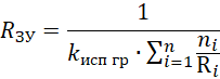
where  is number of sets;
 is utilization ratio;

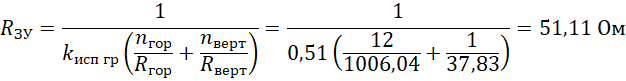
The estimate resistance of the grounding arrangement is 51.11 Ohm.
Grounding performance
Vertical copper-plated steel electrodes 3 m long are used as grounding arrangements. A galvanized steel strip with a cross-section of 40 x 4 mm combining all vertical electrodes is used as a horizontal ground electrode. The distance to the facility foundation is at least 1 m. Strip deepening is 0.5 to 0.7 m.
Rods are connected to the bar using clamps ZZ-005-064.
According to the EIC, item 1.7.103, total dissipation resistance of ground terminals (including natural ones) of all repeated groundings of the PEN wire of each high-voltage line in any season of the year shall not exceed 5, 10, and 20 Ohm, respectively, with linear voltages of 660, 380, and 220 V of a three-phase source or 380, 220, and 127 V of a single-phase source. Wherein the dissipation resistance of the ground terminal for each repeated grounding electrode shall not exceed 15, 30, and 60 Ohm, respectively, with the same voltage values. With soil resistivity > 100 Ohm*m, said standards may be increased by 0.01 times, but not more than by 10 times.
According to RD, item 1.8, artificial ground terminals shall be located under the asphalt coating or in a unfrequented spots (on lawns, at the distance of 5 m or more from soil roads and pavements, etc.).
According to EIC-7 issue, par.1.7.55, Grounding arrangements for protective grounding of electrical installations for buildings and structures and the 2nd and 3rd categories lightning protection of these buildings and structures, as a rule, shall be common.
If there are concrete-steel constructions, they shall be connected to down current collectors/grounding arrangements.
All grounding arrangements should be combined using clamps ZZ-005-064.
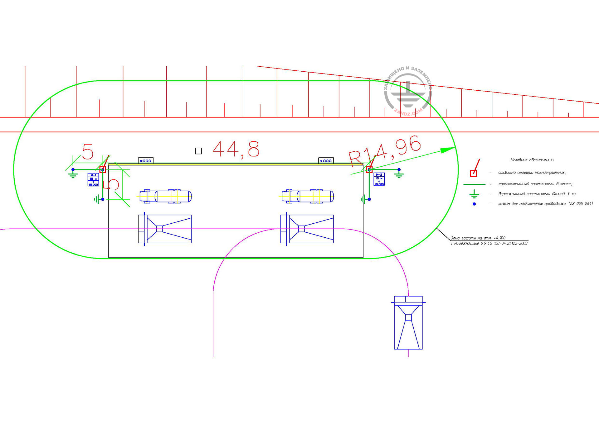
The location of the elements of the lightning protection system and the grounding arrangement is shown in a drawing in a separate file.
_Казахстан.webp)
Click here to view the diagram in full
Условные обозначения - Legend
-отдельностоящий молниеприемник мачта высотой 17 м - 17 m standalone lightning rod
- полоса стальная оцинкованная сечением 40х4 мм - galvanized steel bar 40 x 4 mm
- зажим для подключения проводника - clamp for connecting conductors
- вертикальный заземлитель длиной 3 м - 3 m vertical grounding terminal
Table 1. List of required materials.
| Item No. | Fig. | Part number | Product | Amount |
| Lightning protection system | ||||
| 1 | 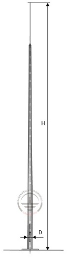 |
ZZ-201-017-В4-Сн3 | 4 | |
| Grounding arrangement | ||||
| 2 | 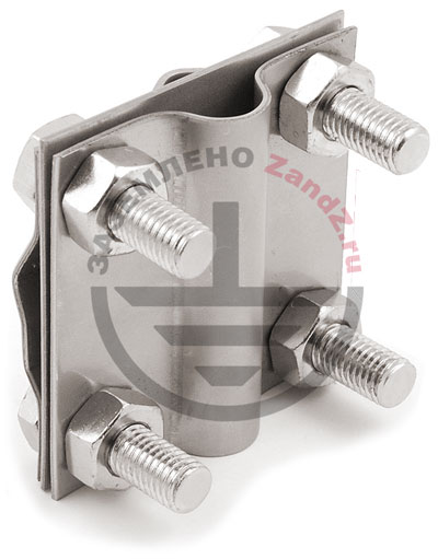 |
ZZ-005-064 |
17 | |
| 3 | 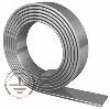 |
ZZ-502-404-38 |
6 | |
| 4 |  |
ZZ-001-065 |
24 | |
| 5 | 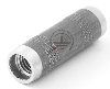 |
ZZ-002-061 |
13 | |
| 6 | 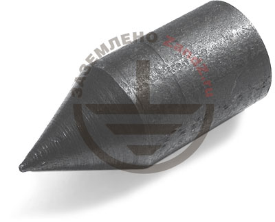 |
ZZ-003-061 |
12 | |
| 7 | 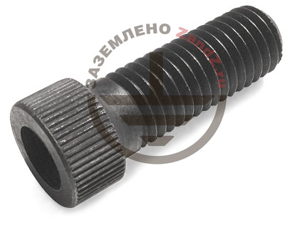 |
ZZ-004-060 |
5 | |
| 8 |  |
ZZ-006-000 |
2 | |
| 9 |  |
ZZ-007-030 |
15 | |
| 10 | 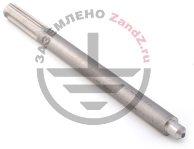 |
ZZ-008-000 |
1 | |
Do you have any questions regarding grounding of a server room or other facilities? Please contact the ZANDZ Technical Center!
Related Articles: