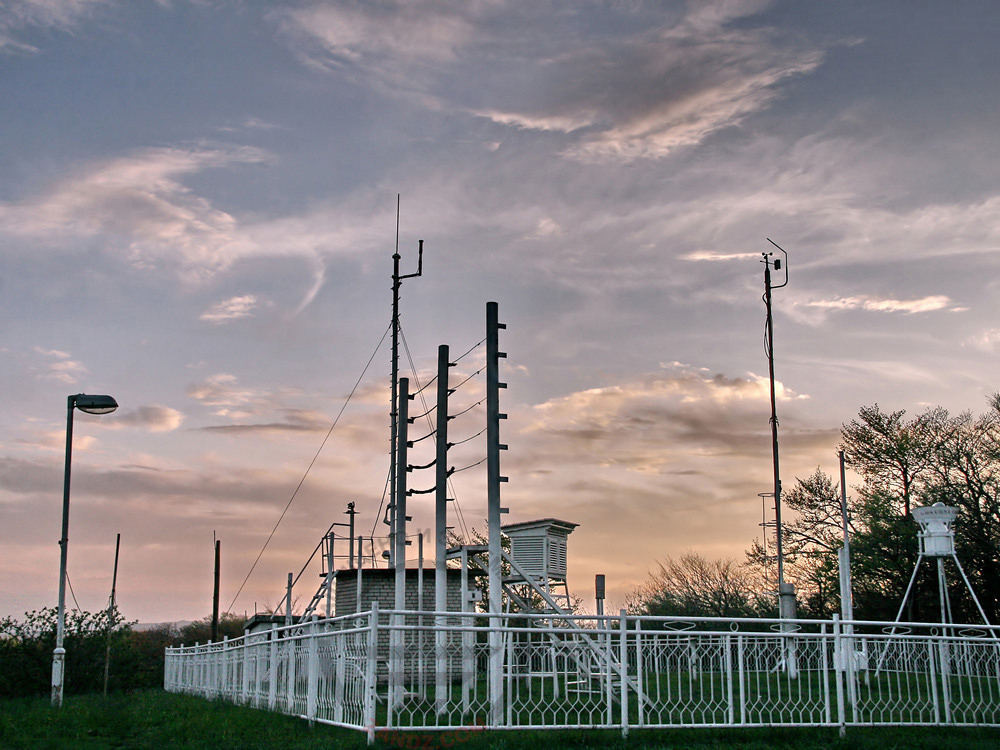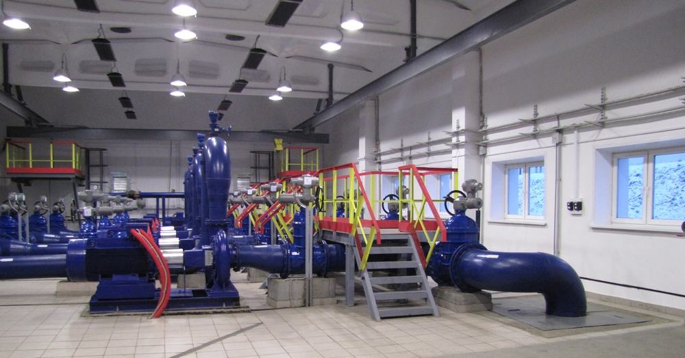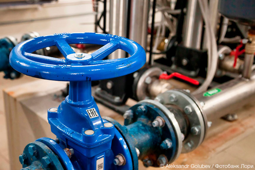
Water supply is a life support system in buildings and structures. Without it, people cannot stay there comfortably. A short search over the Internet will provide a deep understanding of the importance of uninterrupted system operations. Modern water supply systems are complex engineering facilities with a lot of powered equipment as well as low-voltage equipment such as monitoring, dispatcher systems, CCTVs, access control, etc. The water supply system facilities just like any other facilities are prone to lightning strikes; therefore, the absence of reliable lightning protection and grounding are dangerous in terms of the facility damage with serious consequences.
In 2021, the ZANDZ.com Technical Center received a request to calculate lightning protection for a complex of water supply and treatment facilities as well as water supply network in a settlement located in the Khanty-Mansiysk Autonomous Region. We will consider, as an illustration, a solution that was provided by the ZANDZ Technical Center in reply for a complete transformer substation that powers the facility.
Solution:
The activities were conducted in accordance with the Electrical Installations Code (EIC), Rev. 7, Chapter 1.7, SO 153-34.21.122-2003 "Guidelines for Arrangement of Lightning Protection of Buildings, Structures, and Industrial Utilities" (hereinafter referred to as SO), and RD 34.21.122-87 "Guidelines for Arrangement of Lightning Protection of Buildings and Structures" (hereinafter referred to as RD).
The protected facility is classified as a conventional facility in terms of lightning protection according to SO and to Category 3 according to RD.
Protection of buildings against lightning strikes is provided by using lightning arresters. Lightning arrester is a device that is elevated over the protected facility through which the lightning current goes into the ground bypassing the protected facility. It consists of a lightning rod that directly accepts the discharge of a lightning , a current collector, and a grounding electrode.
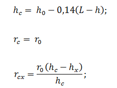
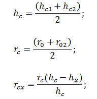
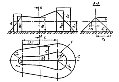
Calculation of protection zones of repeated lightning arresters is performed according to items 2.2 and 3 of Appendix 3 to RD 34.21.122-87 for the zone B. The protection zone of the repeated lightning arresters is defined as a protection zone of the pairs of adjacent lightning arresters. Taking into account that, in this case, the distance between the lightning arresters is greater than the height but less than six heights of lightning rods, we can use the respective set of formulas:
A set of arrangements ensuring compliance with the lightning protection requirements is based on the following solutions:
- installation of 2 x 4 m lightning rods on the wall. It is considered that 0.7 m of the rod length is used for securing;
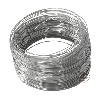
- Lightning rods are interconnected to arrange two current collectors using galvanized steel wire of D = 8 mm from each lightning rod. Current collectors are connected to an artificial grounding arrangement in 8 points. The distance between the current collectors should not exceed 20 m. Current collectors are attached (with mounting step 0.6-1 m):
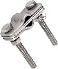
- connection and branching of current collectors are made using clamps GL-11551А.
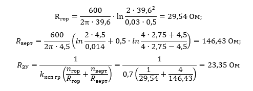
Calculation of grounding arrangement resistance for CTS:
According to engineering and geological survey provided by the customer, the prevailing soil type is sand.
The estimated soil resistivity is taken to be 600 Ohm ∙ m.
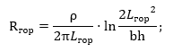
Horizontal electrode resistance:
Гор - Hor
where ρ is soil resistivity, Ohm*m;
b is horizontal electrode width, m;
h is horizontal electrode depth, m;
Lhor is horizontal electrode length, m.
Vertical electrode resistance
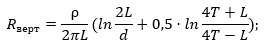
where ρ is soil resistivity, Ohm*m;
L is vertical electrode length, m;
d is vertical electrode diameter, m;
T – is depth, i.e. the distance from the ground surface to the ground terminal, m;

ЗУ - GA
Исп гр - Util
where t is depth of the top of the electrode, m
Electrical impedance of the grounding arrangement:
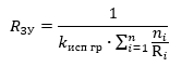
where n is the number of sets;
kutil is the utilization ratio;
Гор - Hor
Ом - Ohm
ЗУ - GA
Верт - Vert
The estimated resistance of the grounding arrangement is 23.35 Ohm, which is less than the required grounding resistance of 24 Ohm obtained by increasing the resistance of
4 Ohm by 6 times according to item 1.7.101 of the EIC Rev. 7.
A set of measures to ensure the requirements for the grounding arrangement is based on the following solutions:
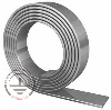
- mounting of a grounding arrangement consisting of a horizontal electrode (galvanized steel strip with a cross-section 4 x 30 mm), depth 0.5 meter, and 15 x 3 m and 4 x 4.5 m vertical electrodes (steel copper-clad rods with a diameter of 14 mm);
- vertical and horizontal electrodes are interconnected and they are attached to the reservoir body and the CTS metal structure using clamp ZZ-005-064;
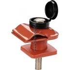
- current collector is connected to the output of the galvanized ground strip using control clamp GL-11562A;
- the design of the grounding arrangement corresponds to item 1.7.55 of the EIC. Grounding arrangements for protective grounding and grounding for lightning protection are common.
The location of the elements of the lightning protection system and the grounding arrangement is shown in a drawing in a separate file. The indicated protection zone corresponds to zone B according to RD.
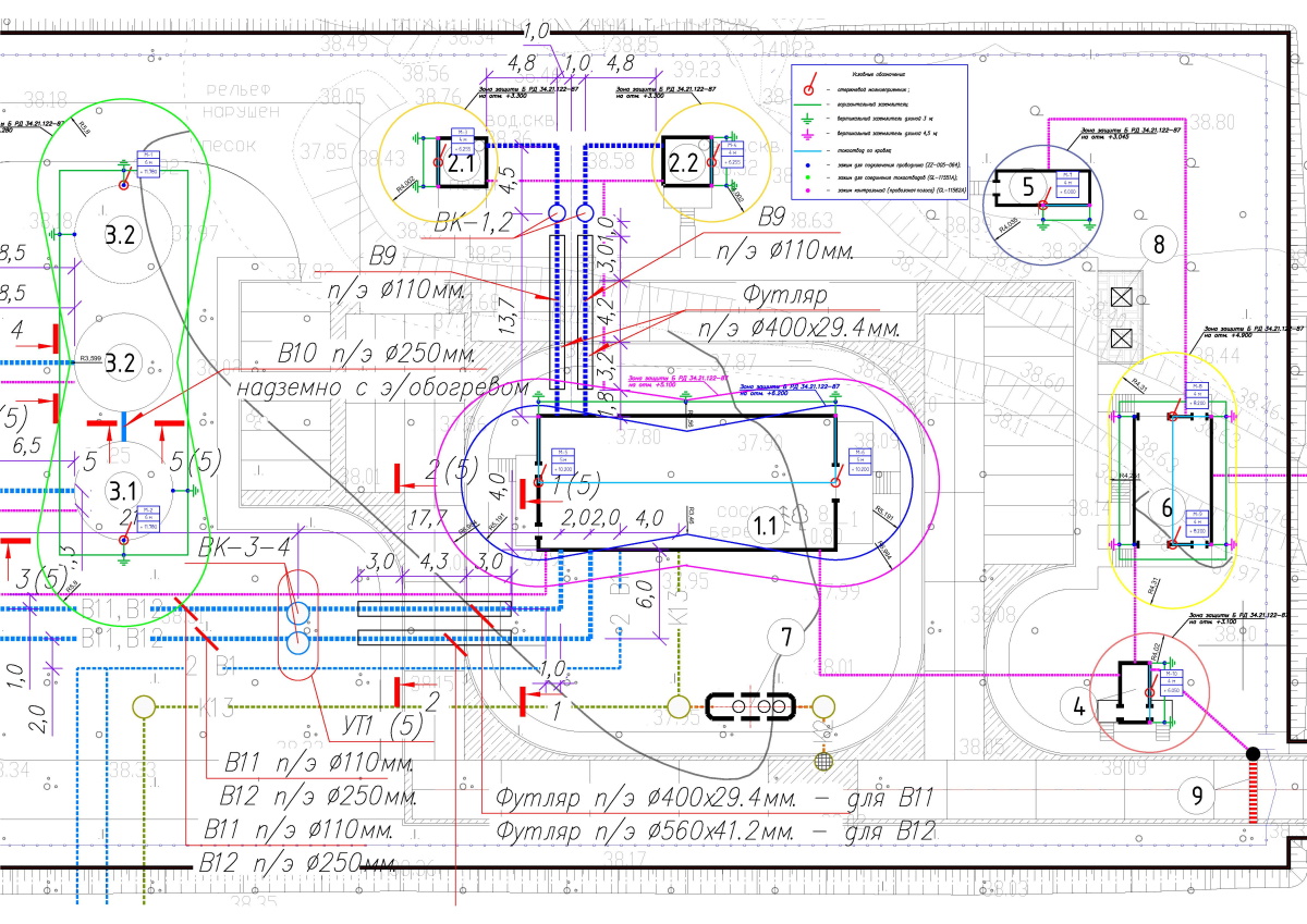
Click here to view the diagram in full.
Условные обозначения - Legend
Футляр - Cover
Мм - Mm
Надземно с э/обогревом - Above-ground with electric heating
Футляр п/э - PE cover
Table 1. List of required materials.


Do you have any questions about lightning protection for the cadet school or other facilities? Please, contact the ZANDZ Technical Center!
Related Articles: