Biofuel is used to replace combustion of fossil fuels in order to prevent climatic crisis. Its combustion results in up to 65% less carbon dioxide emissions compared to traditional power sources. The advantages of the biofuel, in addition to sustainability, include: renewability, engine service life (due to less impurities), and cost-saving - the biofuel production can be located directly at the industrial enterprises which eliminates the need to transport the fuel.
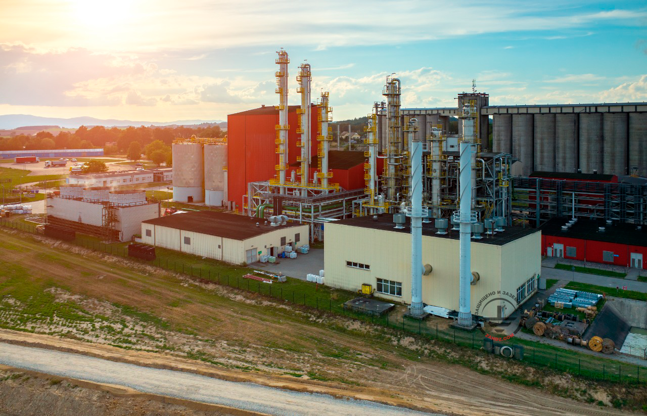
Recently, ZANDZ.com Technical Center has received a request to calculate the lightning protection and grounding for a paper and pulp mill. The facility is a designed area for the production of hard biofuel from sewage sediments and bark and wood waste. The area is located in the same building together with the workshop substation; therefore, the resistance of the grounding electrode should not be more than 4 Ohm. Soil resistivity at the facility at various heights is 18 to 55 Ohm*m.
Main production building and emergency release building (ClassB-IIa zone as per
В-IIа по the EIC, Rev. 7, Chapter 1.7 (hereinafter, the EIC) should be protected as Category II according to RD 34.21.122-87 Guidelines for Lightning Protection of Buildings and Structures (hereinafter, RD), and they are at least 30% of the total area of the building premises. Thus, the protected facility is classified as Category II with the protection zone B as per RD.
Protection of buildings against lightning strikes is provided by using lightning arresters. Lightning arrester is a device that is elevated over the protected facility through which the lightning current goes into the ground bypassing the protected facility. It consists of a lightning rod that accepts the lightning discharge directly, a current collector, and a grounding electrode.
Calculation of protection zones of repeated lightning arresters is performed according to items 2.2 and 3 of Appendix 3 to RD 34.21.122-87 for the zone B. The protection zone of the repeated lightning arresters is defined as a protection zone of the pairs of adjacent lightning arresters. Taking into account that the distance between the lightning arresters is greater than the height but lower than six heights of lightning rods, we can use the respective set of formulas:
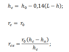
Since lightning rods have different heights, we will use the following formulas to calculate sizes of internal area of protection zones:
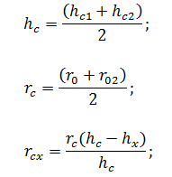
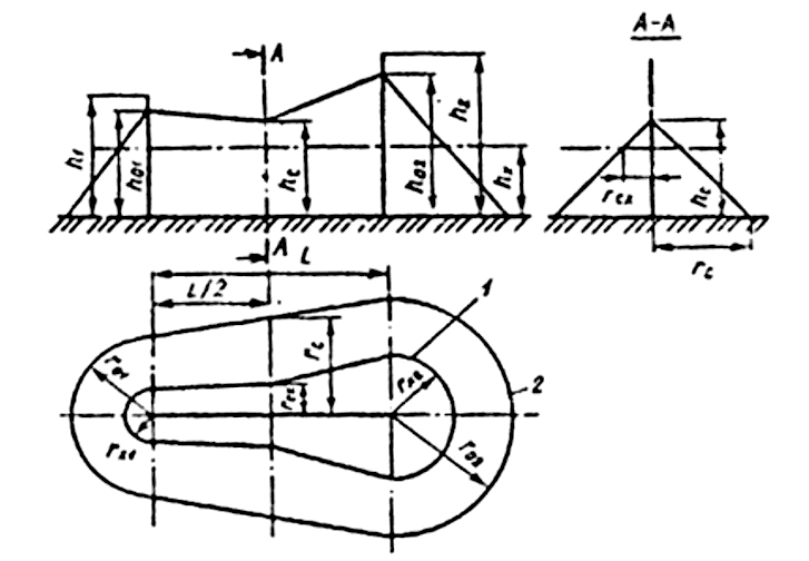
The set of arrangements ensuring compliance with the lightning protection requirements is based on the following solutions:
- Installation of 4 7 m high lightning rods is carried out by attachment to the wall. It is taken into account that 1.5 m of the height of lightning rod is necessary for mounting;
- lightning rods are interconnected to arrange two current collectors using a steel galvanized wire D = 8 mm from each lightning rod. Current collectors are attached (spacing 0.6 to 1 m):
- on the roof using clamps GL-11747A;
- to the walls using clamps GL-11703A;
- on a gutter using clamps GL-11545A;
- connection and branching of current collectors are made using clamps GL-11551A.
A set of measures to ensure the requirements for the grounding arrangement is based on the following solutions:
- mounting of a grounding arrangement consisting of a horizontal electrode (galvanized steel strip with a cross-section 4 x 30 mm), depth of 0.5 meter, and six vertical electrodes (steel copper-clad pins with a diameter of 14 mm), 3 m long;
- interconnection of vertical and horizontal electrodes is carried out using clamps ZZ-005-064;
- connection of the current collector with the output of the galvanized ground strip is performed using control clamps GL-11562A;
- the design of the grounding arrangement corresponds to clause 1.7.55 of the EIC. Grounding arrangements of protective grounding and grounding for lightning discharges are shared;
- grounding may be installed to the PTS from any point of the grounding arrangement;
- according to items 2.22 and 2.23 RD, the protection against high voltage should be made via underground and above-ground utilities by their attachment at the building entry to the grounding arrangement.
The location of the elements of the lightning protection system and the grounding arrangement is shown in the drawing below. The indicated protection zone corresponds to the zone B according to RD.
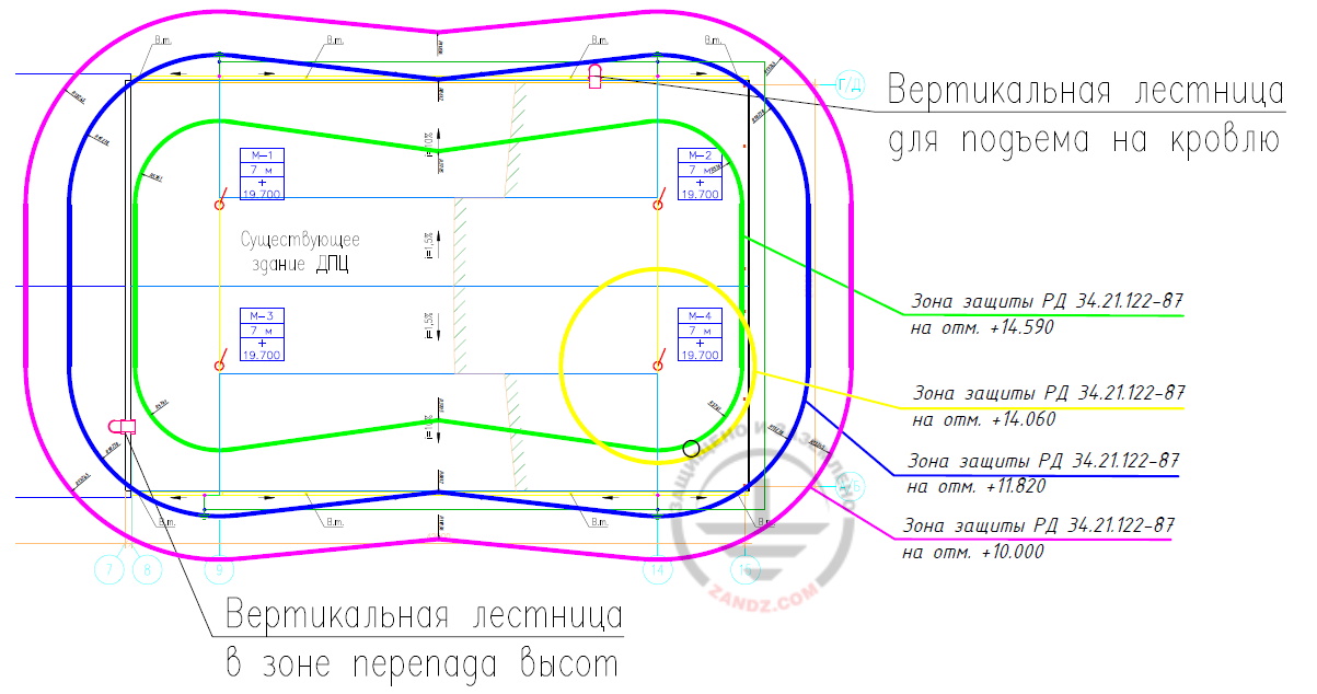
Вертикальная лестница в зоне перепада высот - Vertical ladder in the elevation difference zone
Вертикальная лестница для подъема на кровлю - Vertical ladder to access the roof
Зона защиты РД 34.21.122-87 на отм. +14.590 - RD 34.21.122-87 protection zone at elev. +14.590
Зона защиты РД 34.21.122-87 на отм. +14.060 - RD 34.21.122-87 protection zone at elev. +14.060
Зона защиты РД 34.21.122-87 на отм. +11.820 - RD 34.21.122-87 protection zone at elev. +11.820
Зона защиты РД 34.21.122-87 на отм. +10.000 - RD 34.21.122-87 protection zone at elev. +10.000
Grounding arrangement resistance calculation:
According to the soil corrosivity table provided by the customer, the available soil is sand and clay loam. The estimated soil resistivity is taken as the largest value from the table and is 55.6 Ohm m.
Horizontal electrode resistance

Гор - Hor
where
ρ is soil resistivity, Ohm*m;
b is horizontal electrode width, m;
h is horizontal electrode depth, m;
Lhor is horizontal electrode length, m.
Vertical electrode resistance

Верт - Vert
where
ρ is soil resistivity, Ohm*m;
L is vertical electrode length, m;
d is vertical electrode diameter, m;
T is depth, the distance from the ground surface to the grounding electrode, m;

where
t is the electrode top depth, m
Electrical impedance of the grounding arrangement

ЗУ - GA Исп - Util
where
n is the number of sets;
kutil is the utilization ratio.


Ом - Ohm
The estimated resistance of the grounding arrangement is 1.23 Ohm, which is less than the required value of 4 Ohm.
Table 1. List of required materials.
Do you have any questions about lightning protection for the cadet school or other facilities? Please contact the ZANDZ Technical Center!


