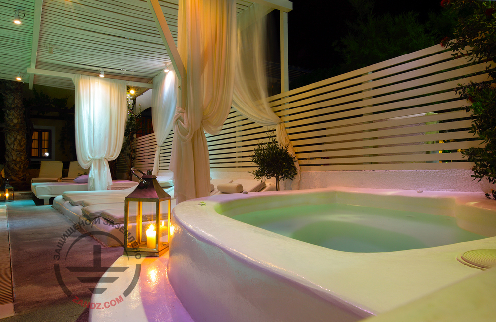
The ZANDZ Technical Center has received a request for the calculation of the lightning protection system for the SPA center. Our engineers have developed an optimal solution that will be discussed further.
Initial data:
-
facility: SPA center;
-
location: Leningrad Region;
-
architectural drawings of the facility;
-
soil resistivity 100 Ohm*m.
Task:
1. Calculate the external lightning protection system.
2. Calculate the grounding arrangement.
The activities have been performed according to:
-
EIC, 7th rev., SO 153 34.21.122 2003 Instructions for Mounting Lightning Protections of Buildings, Structures and Industrial Communications (hereinafter referred to as SO);
-
RD 34.21.122 87 Instructions for Mounting Lightning Protection of Buildings and Structures (hereinafter referred to as RD).
The facility is classified as "conventional" (category IV) according to SO and as category III according to RD. The required lightning protection system reliability should be not less than 0.85 (0.9).
A set of arrangements ensuring compliance with the lightning protection requirements for the SPA center is based on the following solutions:
-
The lightning protection for the facility is made using ridge lightning arresters (GL-11521SS) attached with mounts GL-11525 as well as lightning arrester masts 10 m high (ZZ-201-010-3), which are attached with mounts to the chimney; the distance between the arms is 0.5 to 1 m. The current collector is connected to the lightning arrester with a clamp (ZZ-202-002).
-
A copper-plated steel wire (copper coating thickness is at least 70 μm), d8 mm (GL-11149) is used as a current collector.
-
Installation of current collectors is performed using clamps GL-11747A on the roof and GL-11703A on ramparts and vertical surfaces. The clamp installation interval is 0.8 to 1.0 m.
-
The universal GL 11551A clamp is used to connect the rolled products over the length and in assemblies.
-
All metal elements located on the roof shall be connected to the down conductor using GL 11545A clamps. Stairs, railings, are attached using the GL 11514N ring clamp.
-
Copper-plated steel electrodes 3 m long in the locations of the current collector downdrops are used as vertical ground electrodes. The copper-plated steel strip with a cross-section of 30 x 4 mm, interconnecting all vertical electrodes, is used as a horizontal ground electrode. The distance to the facility foundation is at least 1 m. Strip deepening is 0.5 to 0.7 m.
-
The current collector downdrops are installed each 20 to 25 m along the perimeter.
-
According to EIC-7 issue, par.1.7.55 - Grounding devices for protective grounding of electrical installations for buildings and structures and the 2nd and 3rd categories lightning protection of these buildings and structures, as a rule, shall be common.
-
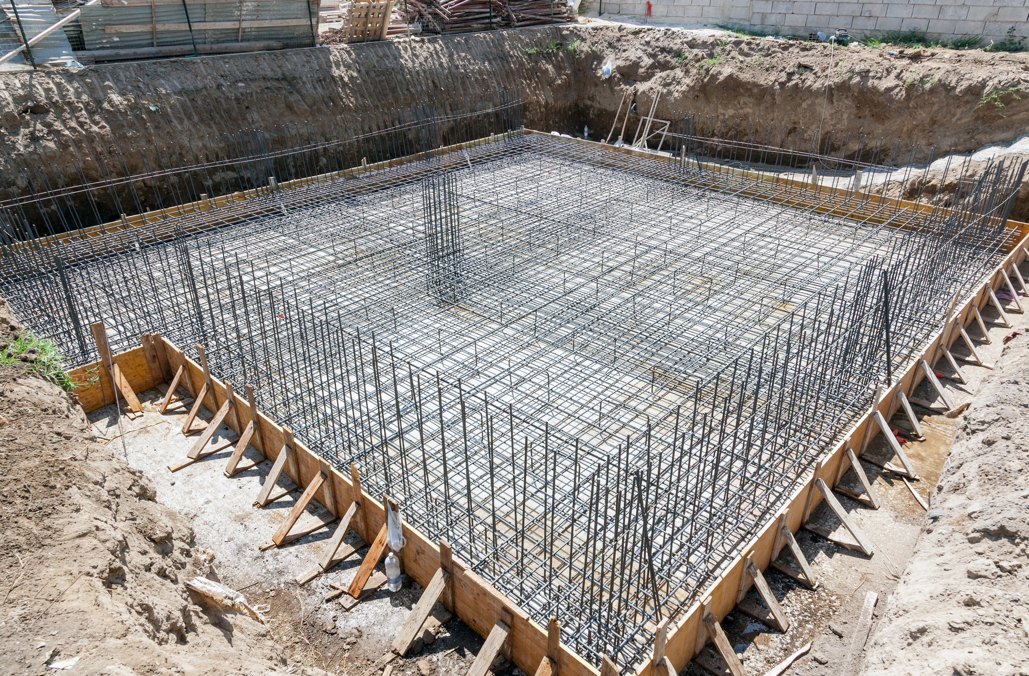
If there are concrete-steel constructions, they shall be connected to down conductors/grounding device.
-
Connection to the grounding device is carried out using ZZ-005-064 clamps.
-
The grounding arrangement is connected to the main board using a conductor ZZ-500-110.
The density of lighting discharge into the ground is 4 strikes/sq. km per year.
The total number of strikes into the system is 0.078 (once every 13 years).
The total amount of breakthroughs (the strikes directly into the facility bypassing lightning arresters) is 0.0083 (once every 120 years).
The system reliability is 0.89.
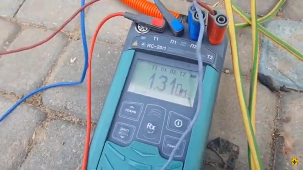
Ground terminal resistance calculation:
Vertical electrode resistance:
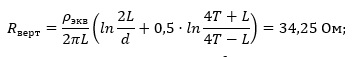
Ом - Ohm
where ρρeq – is soil equivalent resistivity, 100 ohm·m;
L – is vertical electrode length, 3 m;
d – is diameter of the vertical electrode, 0.014 m;
T – deepening - is the distance from the ground surface to the ground electrode, 2 m;
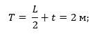
м - m
where t – is deepening of the electrode top, 0.5 m
Horizontal electrode resistance:
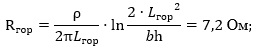
Ом - Ohm
where ρ – is soil resistivity, 100 ohm·m;
b - is horizontal electrode width, 0.03 m;
h - is horizontal electrode depth, 0.5 m;
Lгор is horizontal electrode length, 25 m.
Electrical impedance of the grounding arrangement:
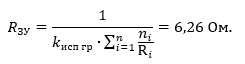
Ом Ohm
where n – is a number of sets, vertical grounding arrangements 2 pcs, horizontal grounding arrangement 1 pc;
Kutil is utilization rate, 0.81.
The design resistance of the grounding arrangement is 6.62 ohm..
The equipment layout and the protection zone are shown in Fig. 1.
The list of equipment and necessary materials is provided in Table 1.
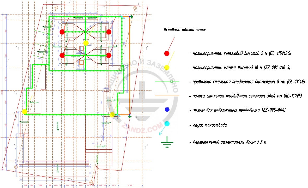
- молниеприемник коньковый высотой 2 м (GL-11521SS) - ridge lightning arrester 2 m (GL-11521SS)
- молниеприемник-мачта высотой 10 м (ZZ-201-010-3) - lightning arrester mast 10 m (ZZ-201-010-3)
- проволока стальная омедненная диаметром 8 мм (GL-11149) - steel copper-plated wire d 8 mm (GL-11149)
- полоса стальная омедненная сечением 30х4 мм (GL-11075) - steel copper-plated strip 30 x 4 mm (GL-11075)
- зажим для подключения проводника (ZZ-005-064) - clamp for connecting conductor (ZZ-005-064)
- опуск токоотвода - current collector downdrop
- вертикальный заземлитель длиной 3 м - vertical grounding arrangement 3 m
Figure 1. Equipment layout. Protection zone.
Table 1. List of needed materials.
| № | Part number | Description | Quantity, pcs. | Unit weight, kg | Note |
| 1. | GL-11521SS | GALMAR 2 meter lightning rod for mounting in threaded holders (M16; stainless steel) | 4 | 10 | |
| 2. | GL-11525 | GALMAR Air terminal crest holder (M16 thread; conductor terminal of d10 mm; bronze) | 4 | ||
| 3. | ZZ-201-010-3 | ZANDZ Tower interception rod type, vertical, 10 m high with a set of 3 wall fasteners (stainless steel) | 3 | ||
| 4. | ZZ-202-002 | ZANDZ Interception rod terminal, D42 mm for main conductor cables (stainless steel) | 3 | 0,43 | |
| 5. | GL-11149-50 | GALMAR Copper-clad wire (D 8 mm/S 50 mm²; 50-meter bundle) | 5 | 0,41 | Weight per 1 meter |
| 6. | GL-11545A | GALMAR Main conductor rain water gutter terminal (painted galvanized steel) | 10 | 0,112 | |
| 7. | GL-11551A | GALMAR Terminal for main conductors connection (painted galvanized steel) | 60 | 0,07 | |
| 8. | GL-11747A | GALMAR Main conductor roof terminal for the roof coated with the metal shape/corrugated sheeting (painted galvanized steel) | 200 | 0,05 | |
| 9. | GL-11703A | GALMAR Conductor front terminal providing 15mm elevation of the main conductor over the terminal (painted galvanized steel) | 50 | 0,02 | |
| 10. | GL-11514N | GALMAR ring clamp on rainwater pipe for down conductor (tinned copper) | 10 | 0,076 | |
| 11. | GL-11075-20 | GALMAR Copper-plated strip (30*4 mm/ S 120 mm²; 20-meter strip bundle) | 2 | 0,98 | Weight per 1 meter |
| 12. | ZZ-001-065 | ZANDZ Copper-plated threaded grounding rod (D14; 1,5 m) | 4 | 2,00 | |
| 13. | ZZ-002-061 | ZANDZ Threaded coupling | 3 | 0,08 | |
| 14.. | ZZ-003-061 | ZANDZ Termination | 2 | 0,07 | |
| 15. | ZZ-004-060 | ZANDZ Guide head for jackhammer attachment | 1 | 0,09 | |
| 16. | ZZ-005-064 | ZANDZ Conductor connection terminal (up to 40 mm) | 6 | 0,312 | |
| 17. | ZZ-006-000 | ZANDZ Conductive grease | 1 | 0,10 | |
| 18. | ZZ-007-030 | ZANDZ Waterproofing tapeя | 2 | 0,40 | |
| 19. | ZZ-008-000 | ZANDZ Attachment to the hammer (SDS max) | 1 | 0,50 | |
| 20. | ZZ-500-110 | ZANDZ Ground cable (10 m; S25; single-wire; with a tip for bolt D8) | 1 | 3,00 |
Do you have any questions about grounding and lightning protection of the SPA center? Please, contact the ZANDZ Technical Center!
Related Articles: