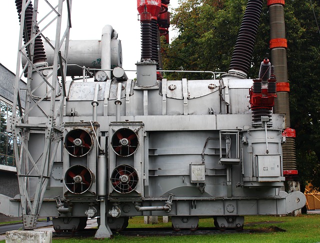
Movable electric installations which allow to solve local needs in electric energy become more and more important. However, these installations require reliable grounding, which must be counted every time depending on the ground, and, of course, lightning protection.

Our ZANDZ Technical Center got a request to solve the task on choosing equipment on lightning protection and grounding of such a movable electric installation. Below we will study the solution we prepared.
Initial data:
- object: FNPP-2500 of a container type;
- sizes of the protected object: 2,5х11,5х3,7 m;
- soil resistivity: 100 Ohm * m.
Task:
Calculate grounding device and lightning protection system.
The arrangements were fulfilled in compliance with:
-
EIC 7th ed (Hereinafter - EIC);
-
IS 153-34.21.122-2003 "Instructions for lightning protection of buildings, structures and industrial communications" (hereinafter - IS);
-
AD 34.21.122-87 "Instructions for lightning protection of buildings and structures" (hereinafter AD).
The object refers to "special with limited danger" in accordance with IS and to the II category according to AD.
Protection of buildings and structures against lightning discharges is ensured by lightning rods. A lightning rod is a device rising above the facility that diverts lightning current into the ground without entering the facility. It comprises a lightning rod that directly receives the lightning discharge, a down conductor and a ground electrode.
In accordance with EIC, 1.7.96 In electric installations with the voltage higher than 1 kV of the net with the insulated neutral, the resistance of the grounding device with the counted ground current going to the ground, taking into consideration all natural ground electrodes should be (at any time of the year)
R ≤ 250 / I,
but not more than 10 Ohm, where l - counted ground current, A.
The following is taken as counted current:
1) in circuits without compensation of capacitance currents - ground current;
2) in circuits with compensation of capacitance currents:
for grounding devices to which compensating devices are connected- current equal to 125% of the nominal current of the most powerful of those devices;
for grounding devices, to which compensating devices are not connected - ground current flowing in this circuit when disabling the most powerful compensating device.
Counted ground current must be determined for the possible circuit layout in which this current has the greater value.
The set of measures to provide the required lightning protection is offered by the following solutions:
-
Lightning protection is implemented with the help of air-terminals masts 4 meters high (ZZ-201-004), which are installed with the help of holders ZZ-203-002. Connection to the down conductors is carried out with the help of clamps ZZ-202-001.
-
Steel copper-bonded wire d8 mm (GL-11149) is used as a down conductor (thickness of the copper bonding at least 70 mcm).
-
Installation of down conductors is performed using GL-11704А clamps. Distance between the clamps- from 0.8 up to 1.0 meter.
-
A universal clamp GL-11551A is used for connecting the mill products along the length and in the nods.
-
Copper-coated steel electrodes 3 m long are used in places of downdrops and in the center as vertical ground electrodes. Copper-bonded steel tape with the cross-section of 30x4 mm uniting all vertical electrodes is used as a horizontal ground electrode. The distance to the object foundation- not less than 1 m. Burial depth of the tape 0,5-0,7 m.
-
In accordance with the EIC-7 ed., P.1.7.55 - Grounding devices for protective grounding of electrical installations of buildings and structures and lightning protection of the 2nd and 3rd categories of these buildings and structures, as a rule, should be common.
-
Connection to the grounding device is carried out with the help of clamps ZZ-005-064.
Grounding device resistance calculation:
Vertical electrode resistance:
where ρэкв - equivalent soil resistivity - 100 Ohm*m;
L – vertical electrode length - 3 m;
d – vertical electrode diameter - 0.014 m;
T – deepening - the distance from the ground surface to the ground electrode system - 2 m;
where t is the deepening of the electrode top - 0,5 m
Horizontal electrode resistance:
where ρ - soil resistivity - 100 Ohm*m;
b - horizontal electrode width - 0.03 м;
h - horizontal electrode laying depth -0.5 m;
Lгор – horizontal electrode length - 11 m.
Impedance of the grounding device:
where n-number of kits, vertical ground electrodes -3 pc., horizontal ground electrode - 1 pc.;
Kисп - utilization ratio, 0.81;
The design resistance of the grounding device is 7,77 Ohm.
Results of calculations for the protection zone in compliance with the IS:
Air terminal mast № 1,2 (ZZ-201-004):
h = 6,7 m;
Height of the cone according to the IS chart. 3.4:
h0 = 0,8*h = 5,36 m;
The radius of the cone according to the IS chart. 3.4:
r0 = 0,8*h = 5,36 m;
Distance between the lightning rods:
L=11,5 m;
The ultimate distance between the lightning rods, according to the IS chart.3.6:
Lmax = 4,75*h = 31,83 m;
L0 = 2,25*h = 15,01 m;
There is no vertical clearance.
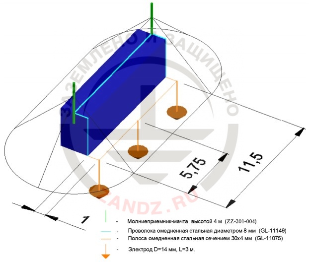
Location of equipment and protection zone are shown in figure 1.
Figure 1 - Location of equipment.
| молниеприемник -мачта высотой 4 м | air terminal mast 4 m high |
| проволока омедненная стальная диаметром 8 мм | copper bonded steel wire 8 mm in diameter |
| полоса омедненная стальная сечением 30*4 мм | copper-bonded steel tape with the cross-section of 30*4 mm |
| электрод D=14 мм,L=3 m | Electrode D=14 mm ,L=3 m |
The list of equipment and required materials is given in Table 1.
Table 1 - Materials requirement list.
Do you have any questions on grounding and lightning protection of movable electric installations? Please contact our ZANDZ Technical center!
See also:
- Unique books for lightning protection designers
- Design of grounding and lightning protection
- Examples of projects we carried out


