From the series of articles "Lightning protection for beginners".
A lightning rod is a simple device. It consists of a lightning rod, into which lightning strikes, and a grounding device through which the lightning current gets into the ground and spreads there. A lightning rod should be metallically connected to the ground electrode. This connectionis providesed by the down conductor. Its function is often performed by the support metal work on which the lightning rod is mounted. In this picture with the reinforced concrete support, you don't see a special down conductor. Here, the lightning current flows to the ground through the reinforced bars hidden in the concrete. It would seem that everything is clear and requires no explanation. Nevertheless, the experts continue to study down conductors more thoroughly every year. Such an increased interest to a passively behaving iron deserves attention.
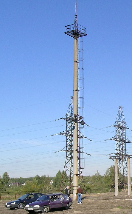
Fig. 1. In this picture with the reinforced concrete support, you don't see a special down conductor
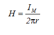
A lightning rod caught a lightning channel and thereby protected the object from a direct impact. But the lightning current IM did not go anywhere. It flows through the down conductor, creating a magnetic field. It is practically the same as in the vicinity of the lightning channel, because the down conductor doesn't change the current value. The magnetic field strength is inversely proportional to the distance r from the collector's observation point.
For a lightning protection specialist it is important, how fast it changed with time. So lightning researchers should provide engineers with is another important parameter - current growth rate at a lightning strike into a lightning conductor. Its registration is not the easiest thing. The sensor must have time to respond to the most transient current spikes. There is even a special sensor characteristics. It is called - response time. In order to measure response time, it is necessary to apply a square signal to the input sensor and see what happens in the output. The reaction won't be instant. Therefore, the output signal front will be smoothed approximately as shown in Fig. 2.
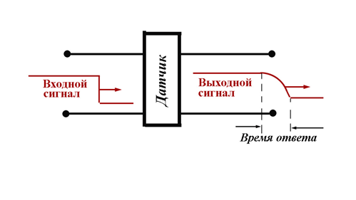
Fig. 2. The reaction won't be instant. Therefore, the output signal front will be smoothed approximately as shown in Fig.
Входной сигнал – input signal
Выходной сигнал- output signal
Время ответа – response time
Датчик - sensor
The duration of the output signal growth to the maximum value determines the response time. With the improvement of the sensors is reduced significantly. In the beginning of the XX century it was about 10 microseconds, today - at least 1000 times less. Now with the improvement, sensors registered lightning with the greater current growth rate AI. The current regulations on lightning protection contain a fantastic value of AI= 2×10¹¹ A / s! Its significance can be felt, based on the law of electromagnetic induction: the current changing with the speed AIexcites EMF in the contour with the square S
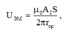
if the contour is removed from the conductor with the current to the average distance rav. In this formula, μ0 = 4π×10-7 H / m - a universal constant called the magnetic permeability of vacuum.
It is necessary to substitute specific values into the formula to estimate what levels of the induced voltage can be discussed. Thus, AI = 2×10¹¹ A / s, contour square S = 1 m, and the average distance to it is 10 m. As a result, the induced voltage is 4000 V. It is necessary to compare this value with an operating voltage of your home electric appliances to imagine consequences of remote lightning effect. In order not to upset the reader, I don't want to remember about the microprocessor technology with the operating voltage of about 5 V. Today it is everywhere-in office buildings, manufacturing enterprises and even homes. Such equipment isn't cheap and the consequences of its damage can be extremely serious. The conclusion can be only one - the magnetic field of lightning should be limited. This can be achieved by removing the lightning rod from the protected buidling. The solution is obvious, though expensive, because a distant lightning rod should be of a greater height. Otherwise, the building won't get into the protection zone. That is why this solution is seldom used in practice. Most frequently, a lightning rod (or lightning rods) are mounted directly on the roof of the building. There is no place to move them to. Only down conductors remain in the hands of an engineer.
The lightning current can be directed to the ground on a single path, or it can be split, loading many rods at the same time. The consequences of such fragmentation are noteworthy.
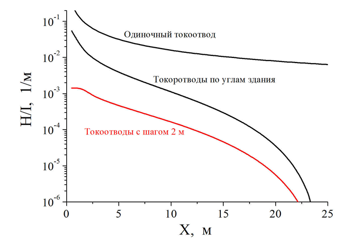
Fig. 3. The formula for the intensity of the magnetic field
Одиночный токоотвод – single down conductor
Токоотводы по углам здания – down conductors at the corners of the building
Токоотводы с шагом 2 м - down conductors with 2 m distance
The formula for the intensity of the magnetic field, recorded above, is fair for a long thin conductor with the current I, which is a single down conductor. It will be forced to transport the whole lightning current to the ground. In fig. 3 (the upper curve) the chart of the magnetic field was built according to this formula in a logarithmic scale for the unit current (H / I value is put on the ordinate axis). The magnetic field from a single down conductor is the most powerful. The next curve in the graph shows how the magnetic field changes on the diagonal of a tall building with the square base of 50x50 meters, when 4 down conductors are located in its corners. For convenience, the distance from the corner of the building, measured along the length of its facade, is put on absciss. In the calculation the current was equally distributed equally between the down conductors (due to full symmetry), and the intensity value in each point was obtained by a vector summing-up of current components in each of the down conductors.
As you can see, the effect is impressive. So, at a distance of more than 5 m from the down conductor, the magnetic field has weakened by almost an order of magnitude compared to a single down conductor. Closer to the center of the building, the consequences became even more noticeable. So there is a direct sense to increase the number of down conductors. This is demonstrated by the lower calculated curve, at the formation of which it was supposed, that the down conductors were placed with the distance of 2 m over the exterior perimeter of the building and their number is 100.
The reader has the right to accuse me of squandering, noting that such lightning protection of high-rise building will require a lot of extra metal. I don't advise to hurry with accusations. In a modern building, many constructions can perform the role of down conductors, for example metal fittings of columns. Fittings of glass units is also very suitable for this purpose, if there is a good contact between them along the entire height of the building. Distance of 2 m in the last chart in Fig. 3 is chosen with the consideration of glass units. It remains to add that weakening of the magnetic field won't lead to exactly the same weakening of EMF of magnetic induction in the internal electrical circuits of the building and all of this with very little additional costs.
Let's study private house bjuildings. As a rule, there are no metal or concrete columns in them, and glass units do not close completely the surface of walls, as in modern high-rise buildings. Lightning rods on the roof of the building, and its roof should be connected with the grounding, by at least two down conductors. A very decent current will flow over each of them at a lightning strike. Of course, the number of down conductors can be increased, but it is not easy to achieve a great effect here- the overall dimensions should be different. The internal electrical equipment of the cottage will have to be protected in a different way. With the help of special devices, limiting electromagnetic interference. Now we will focus on the down conductors. They represent a real danger.
The current in the down conductor creates a voltage drop on it, but not at the expense of resistance (for a thick metal wire it is too small), but in the result of the same electromagnetic induction. Each conductor has an inductance, which is measured in Henry. The inductance of a thin wire is not too high, about 10-6 H per 1 m length. But we should not forget about the extremely high lightning current growth rate AI. Thanks to it, an inductive voltage component appears on L inductance.
The estimation at AI = 1011 A / s allows to feel the order of magnitude of voltage per 1 m of down conductor UL≈10-6× 1011 = 105 B. Voltage of 100 kV should not be neglected. That is why the standards for lightning protection are recommended to be stored in remote places, where people can't reach them.
E. M. Bazelyan, DEA, professor
Energy Institute named after G.M. Krzyzanowski, Moscow
We hope that in the future this site will perform the role of an elementary textbook for self-defense against lightning. We plan to continually post articles about the real dangers of lightning electricity and modern means of lightning protection here. They are designed to help to sort out the existing problems and to estimate the ways to solve it.
See also:
- Free webinars for project designers with Professor E.M. Bazelyan
- Free webinars for project designers with Dr. M. Loboda
- A series of articles "Lightning protection of oil and gas facilities"
- A series of articles "Lightning protection of residential and public buildings"
- Grounding in lightning protection - answers to frequently asked questions in the design
- Consultations on the selection, design and installation of grounding and lightning protection systems
Related Articles:
