TThe third webinar of the Grounding and lightning protection: issues and problems arising in the design series
Webinar text. Page 2
Quick navigation through slides:
<< Page 1:
1. What are SPD designed for
2. GOST R IEC 61643-12-2011
3. SPD as a protection tool against lightning surges in extreme cases
4. Physical mechanism of lightning surge - a resistive component
5. Physical mechanism of lightning surges - EMF induced by the magnetic field of the lightning
6. Surge protection devices
7. Electrical circuit layout
8. Spatial orientation of electric circuits
9. Safe transportation of lightning current into the soil
10. Scanning the magnetic field along the diagonal of the building
Page 2:
11. Interference generating current goes across the shield
12. Interference generating current goes outside the shield
13. SPD operating principle
14. Basic physics
15. Zones protecting electrical and electronic systems from secondary effects of lightning
16. Selection of SPDs for a particular electrical circuit
17. Main parameters of SPDs
18. Rated withstanding surge for different categories of surge
19. List of parameters for selecting surge protective devices
20. Calculation of lightning pulse current going through SPDs
21. The problem of parallel operation of an SPD
Interference generating current goes across the shield
| RU | EN |
| Металлические экраны | Metal shields |
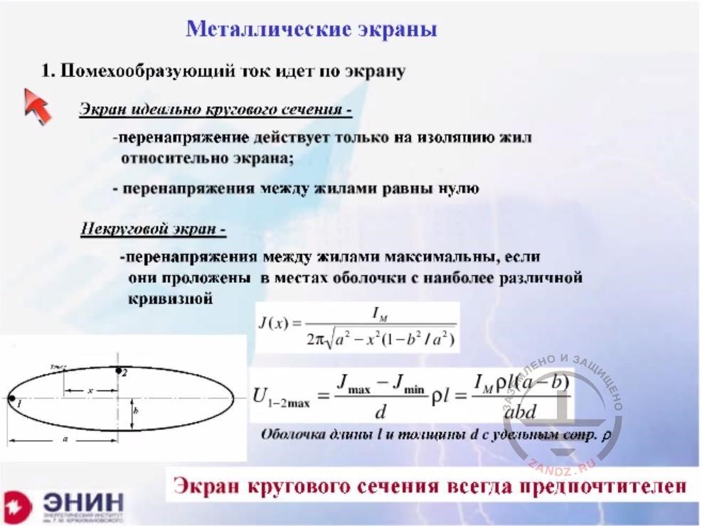
| 1. Помехообразующий ток идет по экрану | 1. Interference generating current goes across the shield |
| Экран идеального кругового… | Shield of ideal circular cross-section - - the surge acts only on the core insulation in relation to the shield; - surge between cores is zero |
| Некруговой экран… | Non-circular shield - - surges between the cores have maximum values if they are laid in the points of the shell with the maximum difference in flexure |
| Оболочка длины… | Shell length l and thickness d with the resistivity ρ |
| Экран кругового сечения… | Shields with circular cross-section are always more preferable |
There is another point, as you have two scenarios related to shields. The first scenario is this: the lightning current flows directly across the shield. Imagine a typical situation: you have a tower. There are obstruction lights installed on the tower. You feed electric power to the obstruction lights using a shielded cable. The situation is like this: if your cable has a circular metal shell, then you get a surge only between the cable insulation and conductor. But you'll have a zero surge between a pair of conductors that supply voltage, e.g. to a chandelier light. For this reason, a circular cross-section shield is perfect. Very often, designers lay cables in cable trays, for example, rectangular trays. But you will never have a zero surge in this kind of trays. The same situation is with trays with any non-circular cross-section, for example, in the form of an ellipsoid, as shown in the picture below. There will be a quite strong surge between the core located in the plane part of the ellipsoid (I've marked it with number 1) and core 2 in the sharper part of the ellipsoid. But if this shield is almost circular, then the voltage of any pair of cores weakens very significantly. For this reason, the ideal shield cross-section is circular.
Interference generating current goes outside the shield
| RU | EN |
| Металлические экраны | Metal shields |
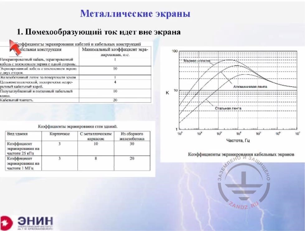
| 1. Помехообразующий ток идет вне экрана | 1. Interference generating current goes outside the shield |
| Медная оплетка | Copper braiding |
| Алюминиевая оплетка | Aluminum braiding |
| Стальная лента | Steel braiding |
| Частота, Гц | Frequency, Hz |
| Коэффициент экранирования кабельных экранов | Shielding factor of cable shields |
Shielding factor of cable shields
| Cable structure | Minimum shielding factor, r.u. |
| Non-shielded cable, shielded cable with shield grounding on one side. | 1 |
| Shielded cable with shield grounding on both sides | 10 |
| Reinforced concrete tray on the ground surface | 1 |
| Full-metal electrically continuous cable tray | 4 |
| Semi-buried and underground cable duct | 10 |
| Cable tunnel | 20 |
Now there's the second scenario: the current does outside the metal screen, i.e. the shield is just a shield. In this case, the shielding effect heavily depends on the shield material. If you shield is made from a copper braiding, an aluminum tape, or a steel tape as shown in the graph to the right, then the order of EMI attenuation is somewhere between 50 and 20, i.e. your electromagnetic interference is weakened by 20 to 50 times. But if you use steel reinforcement bars of a concrete structure as shielding, or you building is made of brick, the magnetic field is shielded by about 3 to 10 times anyway. And this shielding is very substantial, so the electromagnetic interferences in the internal volume of the building are reduced quite significantly thanks to the shielding. And you need to take into account this reduction when you calculate EMI and decide whether it is necessary to apply SPDs.
SPD operating principle
| RU | EN |
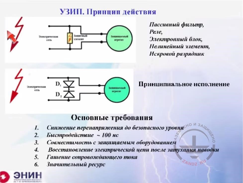
| УЗИП. Принцип действия | SPD operating principle |
| Электрическая сеть | Electric grid |
| Защитный элемент | Protective element |
| Защищаемый агрегат | Equipment to be protected |
| Пассивный фильтр,… | Passive filter, Relay, Electronic unit, Nonlinear element, Spark gap |
| Принципиальное исполнение | Circuit diagram |
| Основные требования… | Main requirements 1. Decreasing the voltage to a safe level 2. Response ~ 100 ns 3. Compatibility with the equipment to be protected 4. Electric grid restoration after EMI attenuation 5. Follow current dissipation 6. Significant service life |
Let's assume you've tried all the above options. And not a single option is satisfying, which means your EMI is higher than needed anyway. Then you really need to install SPDs. What SPDs should do? Their designation is simple. An SPD shunts the circuit at the input of the equipment you need to protect. Thanks to the shunting, the electromagnetic induction does not come into the load, as it is cut-off by the SPD. Generally, you can use whatever you want as the SPDs. You can use a passive filter, or a high-speed relay, or some kind of electronic device. But usually, two components are used. One is a non-linear element on the basis of zinc oxide and the second is a spark gap. Now, what are the requirements for this element? In the figure below, I drew a simple device needed for a sole purpose: once a surge occurs, I have to protect the unit. How can I protect it? Look, I've included two pulse diodes, which are in a closed state if the voltage is lower than their breakdown. But if the voltage exceeds the breakdown threshold, the diodes will breakdown. They will burn to protect the element. They will die to protect the element.
The physical basis
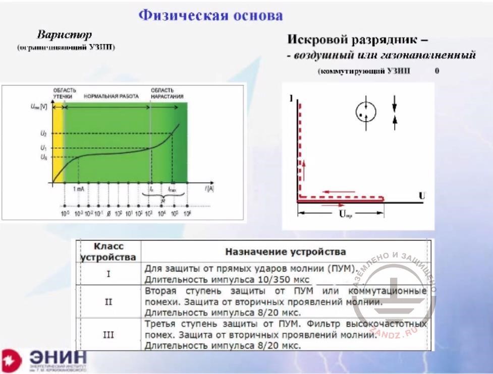
| Физическая основа | Physical basis |
| Варистор (ограничивающий УЗИП) | Varistor (limiting SPD) |
| Область утечки | Leak area |
| Нормальная работа | Normal operation |
| Область нарастания | Buildup area |
| Искровой разрядник - | Spark gap - |
| Воздушный или газонаполненный | Air- or gas-filled |
| (коммутирующий УЗИП | (contact SPD) |
| Класс устройства | Device class |
| Назначение устройства | Device designation |
| I | Protects from direct lightning strike (DLS). Pulse duration 10/350 microseconds |
| II | The second stage of DLS protection or switching noise. Protects from secondary effects of lightning. Pulse duration 8/20 microseconds |
| III | The third stage of DLS protection. High-frequency interference filter. Protects from secondary effects of lightning. Pulse duration 8/20 microseconds |
Once again, as a rule, two versions of the SPD are in use today. One is varistor-based SPDs, which have a current-voltage characteristic shown on the left in the picture. The second are spark gaps, which have a characteristic shown to the right. Both device types are operational, and three classes of such devices are commercially available. The first class is devices designed for the transmission of the full lightning current. They are installed at the entrances to the electrical circuit. Such SPDs are tested by a total lightning current pulse of 10 * 350 microseconds. These devices are most capable and most expensive. The only drawback that these devices have is as follows: while transmitting a rather big current, they still retain a decent voltage on their terminals. This voltage is somewhere around 4 kV. And the voltage of 4 kV is too high for the electrical circuits of buildings because the insulation of internal circuits there usually does not withstand more than 2.5 kV. The second class of devices is also designed to transmit the lightning current, but only partial lightning current on the one hand and electromagnetic interferences on the other hand. As a rule, these devices are tested by a pulse of 8 * 20, not 10 * 350. And these devices are used for protection in places where the full lightning current cannot flow. Finally, there is a third class. Such SPDs are usually installed directly at the input of the protected equipment.
Zones protecting electrical and electronic systems from secondary effects of lightning
| RU | EN |
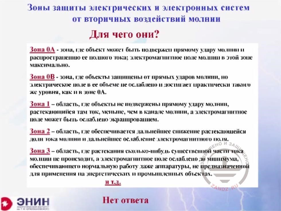
| Зоны защиты электрических… | Zones protecting electrical and electronic systems from secondary effects of lightning |
| Для чего они? | What are they needed for? |
| Зона 0А….Зона 3 | Zone 0A is a zone where a facility may be subjected to a direct lightning strike and the spreading of its full current; an electromagnetic field in this zone has a maximum value. Zone 0B is a zone where facilities are protected against direct lightning strikes but the electric field in its volume is not attenuated and has almost the same level as in Zone 0A. Zone 1 is an area where facilities are not subjected to a direct lightning strike and the current spreading there is less than in the lightning channel, and the electromagnetic field may be attenuated by shielding. Zone 2 is an area where the further decrease of the dissipating share of current and further electromagnetic field attenuation happens. Zone 3 is an area where no spreading of any substantial part of lightning current happens, and the electromagnetic field is attenuated to its minimum. |
| и т.д. | etc. |
| Нет ответа | No answer |
Now, I'd like to discuss things I do not understand myself at all. When people talk about the use of SPDs, they say that you need to follow the zone theory of SPD application. The IEC regulations, and now Russian normative documents, specify several zones that differ in the effects of lightning. The first zone, the so-called zero zone, is an area where the facility is not protected from lightning. The second zone is an area where the facility is protected against the lightning current and magnetic field, but the protection is not full. Finally, the third zone is an area with a partial protection. So there is Zone 1, where the facility is partially protected from the magnetic field, and then there would be Zone 2, followed by Zone 3, and then Zone 4. And as the zone number increases the electric field weakens there. And as I read about it in the normative document, the question arises: why do I need this information? Why do I need these areas? What should I do? I need to do the following. I have is a device and I know what surge this device can withstand. I have this value in the equipment certificate issued by the manufacturer.
Selecting SPDs for a particular electrical circuit
| RU | EN |
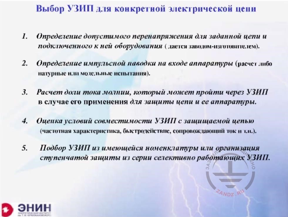
| Выбор УЗИП для конкретной электрической цепи | Selecting SPDs for a particular electrical circuit |
| 1. | 1. Determining an admissible surge for a particular circuit and the equipment connected to it (provided by the manufacturer) |
| 2. | 2. Determining a pulse interference at the equipment input (calculations or field or model tests). |
| 3. | 3. Calculating a share of lightning current that can pass through SPD in case it is used to protect the circuit and its equipment. |
| 4. | 4. Evaluating SPD compatibility conditions with the protected circuit (frequency characteristics, response, follow current etc.) |
| 5. | 5. Selecting SPDs from the commercially available assortment or arranging a multistage protection using a series of selectively operating SPDs. |
Let's go on. Knowing the place where the device is installed, I can calculate a voltage that may occur in the circuit of this device. And I can calculate the electromagnetic interference. I don't have to know, which zone this device is installed in. This is not important for me. I'm concerned about the geometrical pattern I can use for my calculation. The third thing is that I can calculate what amount of the lightning current will get into the protective device, i.e. the SPDs if I install them. I can also calculate this, and I don't need the zone theory for that. Finally, I can determine whether I can put the SPD I want to use in my electrical circuit. Will it match with its frequency characteristics? Will it match in terms of its housing reliability? Will it match in terms of some other operational functions? And I do not need zones for this either. And when I'm done with all the calculation, I take product catalogs supplied by various companies and start looking for a device suitable for my needs. If one device satisfies all my needs, then I will install only one device. If one device is not enough, then I can consistently install a series of devices.
SPD main parameters
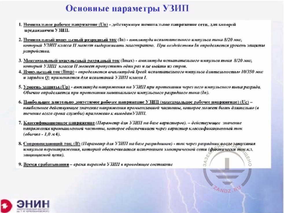
| Основные параметры УЗИП | SPD main parameters |
| 1. | 1. Nominal operating voltage (Un) is a valid nominal grid voltage the SPD is designed for. |
| 2. | 2. Nominal pulse discharge current (In) is the amplitude of test pulse current 8/20 microseconds, which Class II SPD can withstand many times. The device protection level is determined by In. |
| 3. | 3. Maximum pulse discharge current (Imax) is the amplitude of test pulse current 8/20 microseconds, which Class II SPD can withstand once and remain operational. |
| 4. | 4. Pulse current (Iimp) is defined by Ipeak amplitude of test pulse with a duration of 10/350 microseconds and a charge Q; Iimp is used for Class I SPD tests. |
| 5. | 5. Protection level (Up) is the voltage amplitude on the SPD when the pulse discharge current flows through it. It is usually determined when the nominal pulse discharge current (In) spreads. |
| 6. | 6. SPD maximum admissible operating voltage (maximum operating voltage (Uc) is the maximum valid value of industry grade frequency voltage, which can be applied for a long time (during the whole service life) to the SPD output terminals. |
| 7. | 7. Classification voltage (a parameter for varistor-based SPDs) is a valid value of industrial-grade frequency voltage, which provides a classification current (usually 1.0 mA) through the varistor. |
| 8. | 8. Follow current (If) (a parameter for spark gap-based SPDs) is the current coming through the spark gap after the surge pulse attenuation, which is provided by the electric grid source (actually, short circuit current of the protected grid). |
| 9. | 9. Response time is the time of SPD transition to the conductive state |
And I'm going to tell you about the SPD parameters you need to make a choice.They allow you to calculate and determine the necessary SPDs without using any zone theory.What do you need this theory for? I do not understand that.
Rated withstanding surge for different categories of surge
| RU | EN |
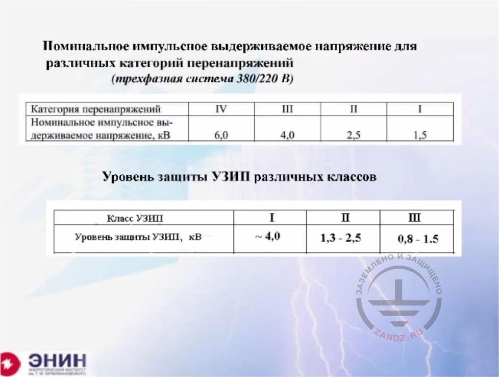
| Номинальное импульсное выдерживаемое… | Rated withstanding surge for different categories of surge (three-phase system 380/220 V) |
| Категория перенапряжений | Surge category |
| Номинальное импульсное выдерживаемое напряжение, кВ | Rated withstanding surge for different categories of surge, kV |
| Уровень защиты УЗИП различных классов | Protection level for different classes of SPDs |
| Класс УЗИП | SPD class |
| Уровень защиты УЗИП, кВ | SPD protection level, kV |
Now let's go on. What do I have? Class 1 SPDs have the voltage of 4 kV on their terminals, and for Class II SPDs it is about 1.5 to 2.5 kV. Finally, for Class 3 SPDs, the voltage may be less than 1 kV. Low-voltage insulation is also divided into categories. There, too, we have four categories. External insulation is for a voltage of about 6 kV. The next class of insulation is for 4 kV. Then comes 2.5 kV followed by 1.5 kV, and the device itself may also withstand a lower voltage. And I need to harmonize SPDs I want to install with the dielectric strength of insulation I have to protect. I have to do this, and I need to know the SPD characteristics for this purpose.
SPD selection parameters list
| RU | EN |
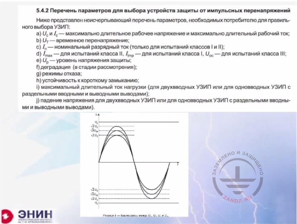
| ****5.4.2 – в колонке EN перевод всего слайда | 5.4.2. Surge protection device selection parameters list |
| A complete list of parameters that a consumer may need to select the right SPD: | |
| a) Uc and Ic – maximum longtime operating voltage and maximum longtime operating current; b) Ut- temporary voltage; |
|
| c) In – nominal discharge current (only for class I and II tests); | |
| d) Imax – for class II tests, Iimp – for class I tests, Ucc – for class III tests; | |
| e) Up - protection voltage level | |
| f) degradation (at the evaluation stage) | |
| g) failure modes | |
| h) short circuit immunity | |
| i) maximum longtime load current (for double-input SPDs or for single-input SPDs with separate input and output terminals); | |
| j) voltage drop for double-input SPDs or for single-input SPDs with separate input and output terminals) |
Now, what our hands-on experience says? The experience says you need calculations. And this is quite obvious. First, you need to understand what current will flow through your SPD after you install it? While you are solving this electrotechnical task, the interests of different SPD manufacturers clash.
Calculation of lightning pulse current going through SPDs
| RU | EN |
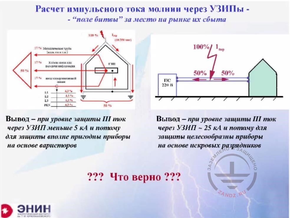
| Расчет импульсного тока молнии через… - - «поле битвы» за место на рынке их сбыта |
Calculation of pulse current through SPDs - - is a battlefield for their sales market |
| Вывод – при уровне защиты III ток через УЗИП меньше 5 кА… | Conclusion: at protection class III, the current through SPDs is less than 5 kA, so varistor-based devices are quite acceptable for the protection |
| Вывод – при уровне защиты III ток через УЗИП ~ 25 кА… | Conclusion: at protection class III, the current through SPDs is ~25 kA, so spark gaps are feasible for protection |
The matter is that each company is trying to justify its products. It says, for example, that it manufactures SPDs unable to withstand the current greater than 5 kA. And this is OK because the current greater than 5 kA cannot get into the SPD under any circumstances. Another firm says "Come on, guys, stop telling this!" A very significant part of the lightning current can enter the SPD, e.g. 20% of the current. That's why you need to by only powerful SPDs, and this is me who manufactures them. And the struggle of these firms suddenly translates into different methodologies proposed to calculate the current flowing through SPDs. Without mentioning the names of such companies, I'll give you two examples. The first case is a lightning strike into a lightning rod installed on a protected building. Let's assume this is someone's cottage. What will the firm that wants to minimize the current say? It will say that the current will flow into the building's ground electrode system through at least two down conductors. But let's assume that this building has a transmission power line, which has four wires: three phase-carrying wires and a neutral wire. Furthermore, a water line made of steel pipes enters the house. In addition, a gas supply line also enters there. And a cable phone line, too. So the current will spread between all these lines in such a way that each such individual utility line accepts approximately the same current. That means that if I take for lines (power supply is one, water supply is two, the telephone line is three and the ground electrode system is four), then I have to divide the current into four parts. Each part is approximately 1/4. But I additionally need to take into account that I have four wires. This means that in each wire the current will be less than 5% of the total lightning current. So when selecting an SPD, I will proceed from the fact that a current of just 5 kA would flow through it (assuming that the lightning current is about 100 kA, as this is the rated current for the third level of protection). So I do not need a powerful SPD, and this is only one aspect. Now, here's the second aspect. Another firm asks the following: does a power line enter the house? Yes, it does. Can a lightning strike into the power line? Yes, it can. How many wires are there in the line? Four. So, 1/4 of the current will flow through each wire. So what rated current do you need for your SPD? You need 25 kA rather than 5, right? What should you choose?
The problem of SPD parallel operation
| RU | EN |
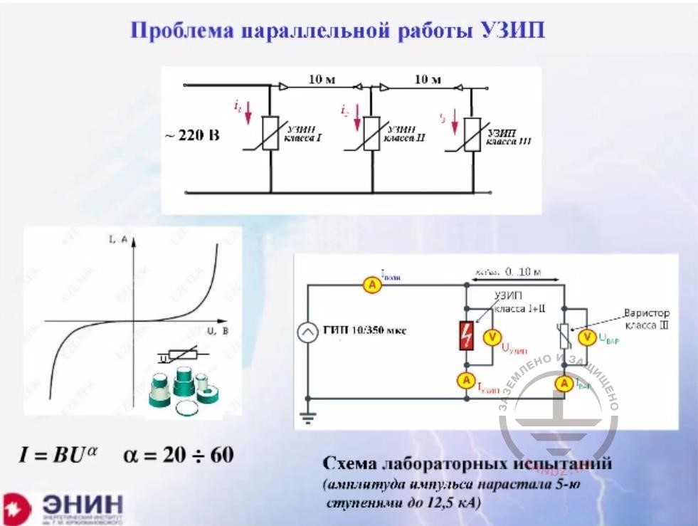
| Проблемы параллельной работы УЗИП | The problem of SPD parallel operation |
| 220 В | 220V |
| УЗИП класс I | Class I SPD |
| УЗИП класс II | Class II SPD |
| УЗИП класс III | Class IIII SPD |
| Схема лабораторных испытаний… | Lab test diagram (pulse amplitude increased in 5 steps up to 12.5 kA) |
| Варистор класса III | Class III varistor |
| ГИП 10/350 мкс | PPG 10/350 mcs |
Now let's discuss the following thing that is very important. If an overhead power line comes to your house and this line is struck by the lightning, then, in any case, you will need the first class SPD that will have a voltage of 4 kV or even more on its terminals. And this is absolutely not enough to protect the electrical circuits and appliances in the house. So you'll have to make a composite lightning protection, i.e. put Class 1 and Class 2 SPD serially, and then install Class 3 SPDs on the protected equipment in order to reduce the voltage from the initial 4 kV to about 1kV, which the insulation of your electronic device in the house can withstand. And the scheme of SPD installation shown here at the top requires the following thing: it requires the selective operation of the SPDs. It is absolutely necessary that the SPD on the input trips first, and the SPD upstream of the equipment trips last. What do you have to do for that? It is recommended to delay the pulse that spreads along the electric circuit. This delay can be achieved in two ways. The first way is to lay a sufficiently long wiring, say 10 meters long, and then your pulse will spread with a delay. Or, if it is impossible to make such wiring, then ensure a concentrated inductance, which provides for the delay. It is written in all manuals, and many catalogs even state the length of the conductor or the value of the inductance. There is no doubt here, and all this is done easily. But there is another thing. Let's assume you've ensured the selective operation. So the first SPD is triggered, then comes the second followed by the third one, and everything's fine. Now they are all working in parallel. And what happens next? Can the following scenario happen: when the lightning current drops after the SPD is triggered, the characteristics of SPDs change in such a way that the input impedance of the third SDP becomes less than the same of the first SPD. Such a thing is really possible. And it is especially possible if you've installed varistor-based SPDs. In the varistor characteristic is very steep. Its current depends on the voltage of several tens of degrees, about 20 to 60. Therefore, it is very difficult to keep the SPD characteristic stable. As a result, you can often face a situation when after the decline of the lightning current pulse, the Class 3 SPD becomes a more favorable path for the current. The Class 3 SPD starts to heat up and fails.
<< Previous Page
Slides from 1 to 10
Next Page >>
Slides from 22 to 25 + questions and answers session
Useful materials for designers:
- Webinars with the leading industry experts
- Everything for the calculation of grounding and lightning protection
- Useful materials: articles, recommendations, examples
Related Articles:
