The second Webinar from the series "Surge protection"
(was held on March 24, 2016 at 11:00 Moscow time)
A skillful use of protection from pulse surges allows to reduce the risk of object damage hit by lightning to an acceptable minimum. In this case, separately used protective elements (arresters, variable resistors and diodes), as a rule, are not able to restrict overvoltages to a safe level on their own and there is a need to unite their positive parameters in protective circuits (SPD) consisting of different types of surge arresters.
The task of the first meeting on the topic "Surge protection of power lines 230/400 V 50 Hz" not to show scientific researches, which have a right to exist, but see the whole diversity of the existing protective means, study practical parameters, which a designer needs to have to build an efficient and reliable surge protection system.
Understanding the differences between these devices will make us better prepare for the next webinars on the topic "Surge Protection"
Full-screen mode with the quality of "720p" is recommended.
Webinar text. Page 1
Quick navigation through slides:
Page 1:
1. Surge protection for power lines 230/400 V 50 Hz Part 1
2. About Miroslav Zelenkevich
3. Main circuit of enabling surge protection elements
4. Cascade protection circuit
5. SPD – the main protection circuit
6. Gas-discharge and semi-conductor devices
7. Spark air gap
8. Forms of gas-filled electrodes
9. Picture of two electrodes
10. Picture of railway line
11. Spark arresters of old type
12. Coal arresters
13. Why coal
14. customer line connection circuit
15. Coal arresters’ operation principle
Page 2: >>
16. Protection of pole-mounted transformer substation
17. Gas arresters of 6 kV line
18. Construction of gas arresters
19. Additional protection element
20. Characteristics of protection element
21. Advantages of gas discharge elements
22. Gas filled arresters
23. Railway arresters
24. Construction of gas filled arresters
25. Gas filled arresters of minor energy
26. Cross section of an arrester
27. Arrester in direct current circuit
28. Arrester in alternate current circuit
29. Sine-wave voltage impact on an arrester
30. Arrester - pulse dialling
Page 3: >>
31. Residual pulse, missed by the arrester
32. Maximal voltage value
33. Discharge action steps at the protection of a device
34. The main parameters of arresters Part 1
35. The main parameters of arresters Part 2
36. The main parameters of arresters Part 3
37. Advantages of gas-filled arresters in low-frequency circuits
38. Example of electrical parameters of a 3- electrode arrester
39. Disadvantages of arresters in low-frequency circuits
40. Lightning current arresters
41. Arresters with arc division
42. Approximate parameters of arresters
43. Main application conditions for surge protection purposes
44. Dynamic pick-up voltage
45. HF and SHF elements
Page 4:>>
46. Semi-conductor surge protection elements
47. Variable resistors
48. Characteristics of U-I variable resistor
49. Structure of ZnO – variable resistor
50. Sizes of ZnO – variable resistor
51. Mono-crystal lattice
52. Three areas of volt-ampere characteristics
53. Advantages and disadvantages of ZnO variable resistors
54. Parameters of variable resistors Part 1
55. Parameters of variable resistors. Part 2
56. How to choose a variable resistor correctly?
57. Protective diodes.Types
58. Protective diode on an example of TRANSIL device structure
59. Designed diodes
60. Response characteristics
Page 5:>>
61. Types of protective diodes by the execution method
62. Advantages of protective diodes
63. Disadvantages of protective diodes
64. Protective diode operation stages
65. Protected device surge resistivity
66. Detector input circuit protection
67. Line repeater of phone line communication protection
68. All-round choice
69. Special purposes in surge protection of circuits
70. Low-voltage electricity supply surge protection
71. Arrester’s connection circuit in a construction project
72. Steppable cascade
73. Electricity supply network surge protection
74. Dynamic pickup voltage
75. Questions and answers
Estimated reading time: 1 hour 29 minutes
Surge protection for power lines 230/400 V 50 Hz. Part 1
- Good afternoon, dear colleagues. We are delighted to welcome you at the new webinar dedicated to surge protection - it is our second webinar. There will be 4 webinars ahead, please sign up so you don't miss anything. Visit out next online meetings, please. The recording of the first webinar is available on our site. It was called zonal concept of lightning protection. I will send the link to the chat a bit later. You can sign up for the next webinars on the same site as well. The topic of the today's webinar sounds like - Surge protection for power lines 230/400 V, part 1. Next Wednesday we will hold the webinar on the second part. The topic is wide, and it was decided to divide it into two online meetings in order to discuss all main questions.
About Miroslav Zelenkevich
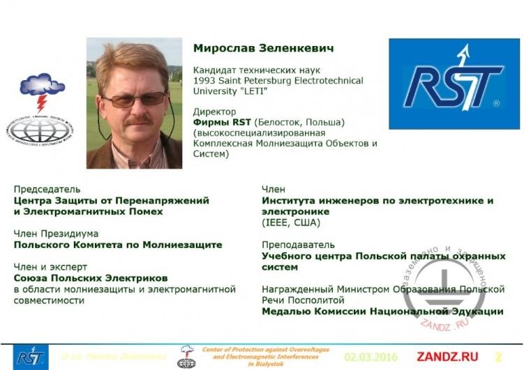
Miroslav Zelenkevich
Candidate of technical sciences 1993 Saint Petersburg Electrotechnical University “LETI”
Director of RST company (Belostok, Poland) (Highly-specialized complex lightning protection of objects and systems)
Chairman of the Center of Protection from Surges and Electromagnetic Pickups
Member of Presidium of the Polish Lightning protection Committee
Member and expert of the Union of Polish Electricians in the area of lightning protection and electromagnetic compatibility
Member of the Institute of engineers on electrotechnics and electronics (IEEE, USA)
Teacher of the Educational center of the Polish chamber of security systems
Awarded by the Ministry of Education of the Polish-Lithuanian Commonwealth by the Medal of Commission of National Education
- And today, in the beginning there will be a small excursus on the topic of elements and circuits of surge protection, during which we will study and compare the main principles of high-voltage semiconductors SPDs. It is necessary to get ready to the next reports and understand what we will be talking about. The lecturer of this series of webinars is a recognized expert in the field of lightning protection and grounding - Miroslav Zelenkevich. Here is here, as you see and I will soon give the floor to him. My name is Alexey Korytko, I am an administrator of this webinar and I will respond your questions and comments, so you can leave them in the chat. You can leave questions in the chat, which is located in the bottom left. The questions will be answered at the end of the webinar. The webinar will last from 60 to 100 minutes approximately. There may also be charts with small details in the presentation. In order to see everything well, please use the buttons for enlarging the scale. It is in the bottom panel under the slides - a magnifier with a green plus. And you might also need the volume regulation for me and the lecturer. For that, you can point the cursor to the video stream that means to my picture or to the picture of video with Miroslav. There will appear a cursor with the help of which you will be able to make sound louder or quieter. I guess all the organization questions are over for now. I am happy to give the floor to Miroslav. I will send the link to the video recording and to the registration to the next webinars. Thank you, Miroslav, good afternoon!
-Hello, dear colleagues! See slide 1. Today I decided to add an introduction part into the first part of surge protection of power lines 230/400 V 50 Hz network so we better understand what we are going to talk about at the next seminars. I simply reviewed what was going on at the webinars held by my friends from Aksu. And I noticed that it can be necessary for you to understand better and easier. Maybe some of you have this knowledge but probably not in the direction I am going to talk in. So my goal is not to show you the scientific results of researches for these elements, but simple practical elements required to the designer so he could choose the elements, devices, circuits which he really needs for the surge protection in this sphere. But here an area is just an electrical network, as it is usually called in the standards - to one kilovolt. It is different from high-voltage by energy and voltage, so we will only focus on these elements.
Main circuit of including surge protection elements
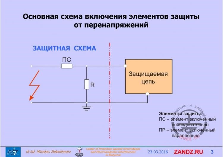
Защитная схема – protective circuit
ПС – sequence element
Защищаемая цепь- protected circuit
Элементы защиты – protection element
ПР – parallel element
- First we need to make an agreement. I have a small mistake here, if you see a parallel element, marked with letter R at the right bottom, it should be PR that is a parallel element. If we look at the surge protection circuit, we, being designers, need to think what we will put. There are two possibilities here: we can connect parallel and sequence elements. What really exists today? If we look at the sequence element which can protect our circuit, the first thing that comes on our mind is a fuse which necessarily activates at the short circuit. But the difference between the short circuit current and overvoltage current is in time. Short circuit is a millisecond time, overvoltage- is microsecond. It is a thousand time difference in time. As life shows, the fuse has no time to activate during overvoltage action. They activate, but as a consequence of overvoltage impact on the protected circuit is when the protected circuit is demolished and the short circuit current is there and the fuse blows. So in this place we can use anything as a sequence element, even such a well-known element as a thermistor. Thermistors are used in phone circuits, networks, for example. But the response time is seconds that is too long, because a surge is microseconds. Time of surge front growth is about 10 ms, which is why they should be protecting at this front. We need to limit overvoltages at the current and voltage pulse front, so the response time should be a bit quicker than 10 ms. I can tell that coming from my practice it means that only one device can be sequence, but it is not practical because it is a superconductor.
Cascade protection circuit
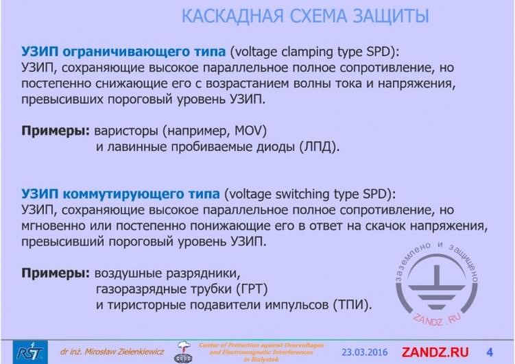
Voltage clamping type SPD - SPD keeping full high parallel resistance, but gradually decreasing it with the increase of the current and voltage wave, exceeding the threshold level of SPD. Examples: variable resistors (for example, MOV) and avalanche breakdown diodes
Voltage switching type SPD – SPD keeping full high parallel resistance, but instantly or gradually decreasing it in response to the voltage surge, exceeding the threshold level of SPD.
Examples: air gap lightning arrester
Gas discharge pipes
And thyristor pulse suppressors
- If we look at the activation method of such elements, on the method of overvoltage suppression, you will see two types of such elements in the standards that are SPD of a limiting time and SPD of a commutation type. In English it is voltage clamping type SPD (SurgeProtectionDevice). Voltage clamping type SPD is an SPD of commutation type. SPD which limits overvoltages is an SPD keeping high and parallel full resistance, which gradually reduces with the increase of current and voltage wave, when we exceeded the threshold level of SPD, the threshold level of activation of our device. A variable resistor and avalanche diodes are examples of such elements. SPD of commutation type is an SPD which keeps high parallel full resistance, but instantly or gradually reduce it, when overvoltage comes, exceeding the threshold level of SPD's activation. These two elements are the base for all protection circuits. An example of such a commutation type are air gaps, gas filled dischargers and thyristor pulse suppressors. The name "gas filled discharges" is a bit strange to me, that's why I never used it and never will, but I guess it is more familiar for you.
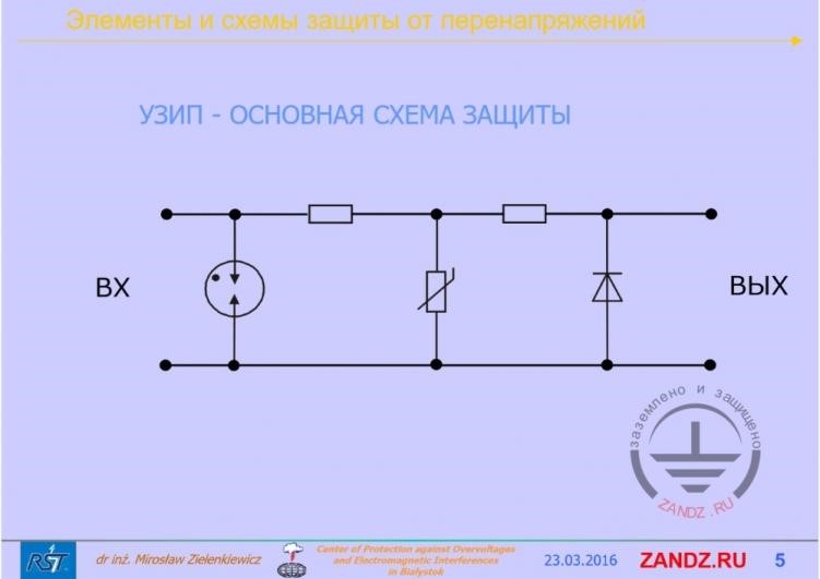
SPD - basic connection circuit
Элементы и схема защиты от перенапряжений- elements and protection circuit from surges
Вход - input
Выход - output
- How SPD circuits are being built? How do these elements activate? I listened to some webinars; I heard some things which are not clear to me, so I am presenting my point of view on this issue. I hope it will be more clear for you, if not, please ask your questions. I will repeat this scheme in the next webinars so this knowledge will be fresh in your mind. Because they are really important. If we look at these elements, and I will talk about each of them in detail today, we will see that there is this discharger on the left. The point in the circle means it is gas filled. The next element is a variable resistor element. And the final stage of this SPD is a diode. One diode is included here. There should be two diodes here, they should be counter-currently included, but I am showing you this chart for simplicity. If we look at this element we see that there are some mating components between the SPDs cascades. In practice it is mainly inductivity, but rarely it can be resistances, and in high-frequency circuits it is simple condensers. Let's concentrate on one element here, we call it inductivity. And this inductivity in electrical networks is a simply inductivity of wires, the own inductivity of wires which are between the sequence elements included into electric supply lines. In the new SPDs, which consist of several cascades-two or three, such inductivities are simply artificial inductivities, included specially between these cascades. Let's study such a scheme, such a variant in which our overvoltage come from the left to the entrance and get on our circuit. And here we have a question: and what element will activate first? I think it is obvious that the quickest will respond first. In practice it is a semi-conductor, a diode. Its automatic response time is microseconds. The next element is a variable resistor. Response time is indicated by the manufacturer about 10-20 nanoseconds.
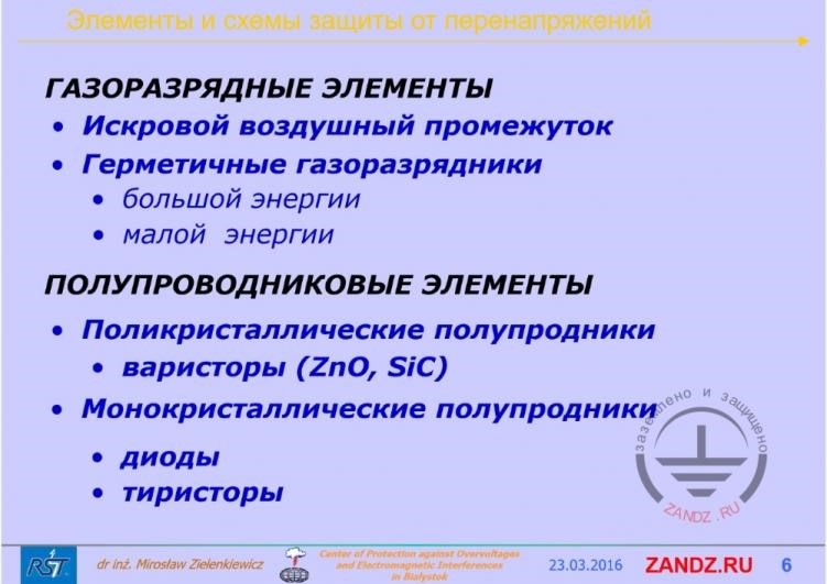
Gas-filled and semi-conductor elements
Элементы и схема защиты от перенапряжений- elements and protection circuit from surges
Газоразрядные элементы – gas discharge elements
Искровой воздушный промежуток – spark air gap
Герметичные газоразрядники – hermetic gas discharges
Большой энергии – of great energy
Малой энергии – of minor energy
Полупроводниковые элементы- semi-conductor elements
Поликристаллческие полупроводники – polycrystal semiconductors
Варисторы – variable resistors
Монокристаалические полупроводники – monocrystal semiconductors
Диоды - diodes
Тиристоры - thyristors
- That is in practice, surge protection elements use certain physical phenomena, that is a puncture in gas, electric puncture in gas and switching of a semi-conductor to the conductive state, so if we look at the elements which are given here. Using spark air gaps, using hermetic gas dischargers, and I am indicating those of great and minor energy. Meaning that minor energy dischargers are used on electronic plates. And of a great energy are those which are installed in electric supply networks, they drain partial lightning currents. Semiconductor elements, which are listed here, are polycrystal semiconductors, variable resistors - mainly zinc oxide is used for them. And there are such elements now and then as silicon carbide. And monocrystal semiconductors, diodes or thyristors.
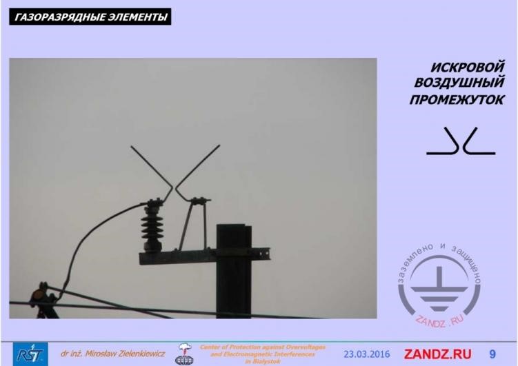
Spark air gap
Элементы и схема защиты от перенапряжений- elements and protection circuit from surges
Газоразрядные элементы – gas discharge elements
SPARK AIR GAP
Spark air gap (we can include coal dischargers here) are devices not possessing a frame insulating active inter-electrode space from the exterior environment.
Due to the fact, that there happens an unfavorable accumulation of particles and grains in the gap, which in its turn brings to the dependence of puncture characteristics because of the current atmosphere state (humidity, temperature, pressure). It is also characterized by mechanic instability.
It is recommended to use spark air gaps only as a reserve working in case of an accident of other more precisely protected elements.
- I think it is clear to everybody that spark air gap is the first element which appeared as overvoltage protection. It is clear that as soon as power supply networks appeared, air power supply networks, we immediately started to have overvoltage problems. Usual switching of power supply network or disabling of power supply network means that there is overvoltage in it, because electric supply network can't instantly discharge the accumulated energy. And in some time, this energy will walk around our networks, forming daily and routine overvoltage, which get on our devices. And then they started to think how to protect and the first element was spark air gap. Then coal dischargers appeared. Spark air gap are devices that do not possess any frame insulating active space between the electrodes on the environment. It means that there may happen an unfavorable accumulation of particles and fibers in the spark gap. For example in the transformer room, it is closed, there are walls in it, and there is no wind. Such accumulation may bring to the activation in some time.
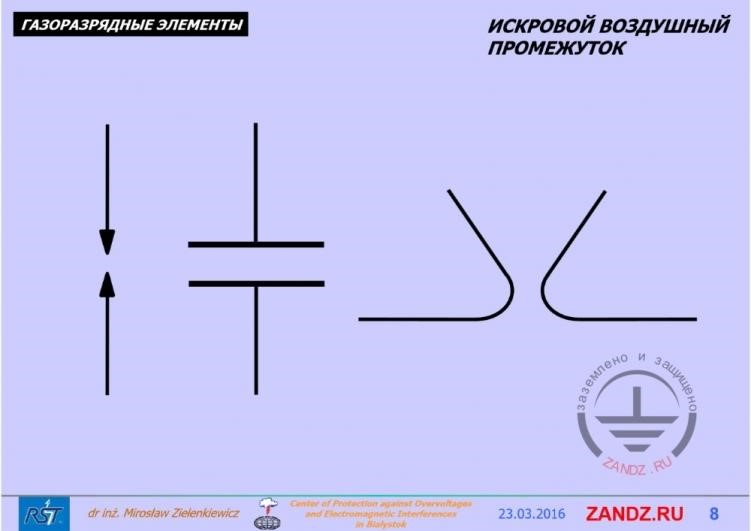
Forms of gas discharge elements
Газоразрядные элементы – gas discharge elements
Искровой воздушный промежуток – spark air gap
- If we look at the forms of such elements, but spark air gap should be necessarily present. On the left there is only a discharge between the plates or just a protective horn, which is still used for the protection of railway lines power supply.
Picture of two electrodes
Газоразрядные элементы – gas discharge elements
Искровой воздушный промежуток – spark air gap
- It is indicated here on the picture. These are just two electrodes. The left electrode is connected to the conductor, and the right one is simply grounded or connected to the reverse.
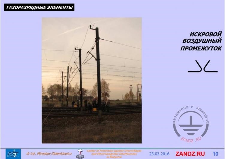
Picture of railway line
Газоразрядные элементы – gas discharge elements
Искровой воздушный промежуток – spark air gap
- If we look at the next picture, we will see that there is a plenty of devices which are able to drain partial lightning currents. In case when lightning gets into a railway line and these elements work well for years. There is only one question left: what is the response accuracy and what is the protection level visible by such devices? Considering that railway is being computerized recently, I think all these elements require work on their quality.
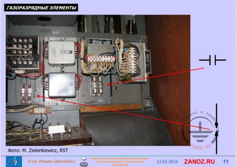
Spark dischargers of old type
Газоразрядные элементы – gas discharge elements
- if we look at the next spark discharges, we will see the old type dischargers on the left. They were used as a reserve, because on the right you see gas-filled discharges with a body frame.
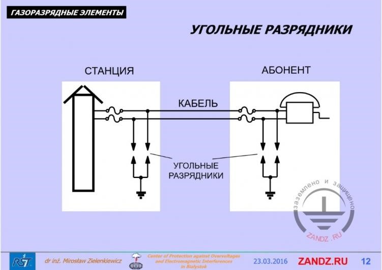
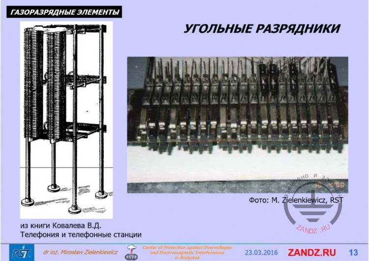
Coal dischargers
Газоразрядные элементы – gas discharge elements
Станция- station
Кабель- cable
Абонент - subscriber
Угольные разрядники – coal dischargers
- The problem appeared in the phone lines, because their length is immense, like of the energy lines. And the first problems come from telecommunication conductive systems. On this slide we see a picture from the old documents, where we see stations protection and surge protection of a subscriber. At the moment, coal dischargers started to be used.
Why coal?
Газоразрядные элементы – gas discharge elements
Угольные разрядники – coal dischargers
- Why coal? Because it was defined that the properties of such coal electrodes are very good and as you see they were applied in Russia and in other countries. Such dischargers were installed at the entry of all the external lines, but they all had serious shortcomings.
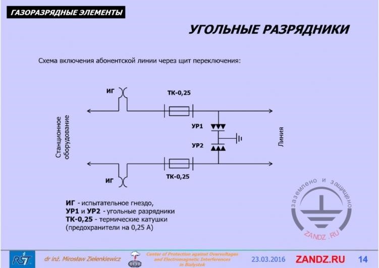
Subscriber line connection circuit
Газоразрядные элементы – gas discharge elements
Угольные разрядники – coal dischargers
Схема включения абонентской линии через щит переключения – subscriber line connection circuit through the switch board
Станционное оборудование – station equipment
Линия - line
Испытательное гнездо – test jack
Угольные разрядники- coal dischargers
Термические катушки – thermal coils
Предохранители на 0,25 А – fuses for 0,25 A
- if we look at this connection circuit - it is a classical circuit and it is used today. The discharger is connected between two lines and two elements are shorted to the ground.
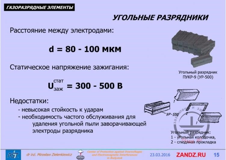
Operating principle of coal dischargers
Газоразрядные элементы – gas discharge elements
Угольные разрядники – coal dischargers
Расстояние между электродами – distance between the electrodes
Статическое напряжение зажигания- static starting voltage
Недостатки - disadvantages
Невысокая стойкость к ударам – low strike resistance
Необходимость частого обслуживания для удаления угольной пыли заворачивающей электроды разрядника – Need of frequent maintenance for removing coal dust that curves the arrester’s electrodes
Угольный разрядник- coal discharger
Угольная колодочка – coal shoe
Слюдяная прокладка- mica separator
- Their response principle is like in an ordinary discharger. We see two coal electrodes here, insulating strip between them which is 80-100 mcm thick. Static starting sparking voltage for such a device is 30--500 V, quite high. But the disadvantages appear here, because it turns out that these elements possess low strike resistance.
Next Page >>
Slides 16 to 30
Useful materials for designers:
- Webinars with the leading industry experts
- Everything for the calculation of grounding and lightning protection
- Useful materials: articles, recommendations, examples
Related Articles:
