International classification and coding of power supply systems
In describing the power supply systems in this article, we will be guided by the materials and standards of the International Electrotechnical Commission (IEC) and the Russian "Electrical Installation Code" (EIC).
Based on the regulatory documents mentioned above, descriptions of power supply systems in the design vary depending on the grounding methods used in distribution networks. Specialists use various types of techniques in the field of protection from negative factors of electric shock. In practice, electrical engineers face functional and protective grounding.
Functional grounding serves to ensure the normal operation of electrical appliances. But for the purpose of ensuring the safety of electrical networks and electrical installations, protective grounding is used at the facilities.
Varieties of artificial grounding systems
Let's consider the basic concepts and tell you what the letter designations used by electricians mean.
The term "zero working conductor" is often used in documentation of power supply, or otherwise it is designated as "N-conductor". It is used to power the receivers of electricity, serves as a connecting part for the output of neutral equipment, which is deadly grounded. In different cases, it is used both in single-phase / three-phase alternating current sources and in DC networks.
But in case when the two conductors described above combine their functions in one conductor, then the concept - PEN-conductor is introduced.
Proceeding from the rules of IEC, and also using the coding system adopted there according to (GOST R 50571.2-94 "Electrical installations of buildings. Part 3. Key Features "), we will tell you about special letter symbols that are accepted in this field of knowledge.
In this terminology, the first Latin letter denotes the state of the neutral source of power in relation to the "ground".
If there is a neutral that is grounded, then we write T (Terra, in Latin for "ground"). If we are talking about an isolated neutral, then we use I (English, Isolate). When identifying the grounding types of ECP (exposed conductive parts), use the letter number two. The Latin T is used in case of a power source isolated from the communication with the ground, grounding of ECP. And the N mark is labeled if ECP directly contact with the grounding point of the power source. A few more Latin letters are used as descriptions of different states of the PE-conductor and N-conductor.
When using separate conductors, N and PE in the scheme, S is used (from the English term Separated).
But if a PEN-conductor is used, in which the functions of both the zero protective and the zero working conductors are connected, they are designated by the letter C (from the English word Combined).
Now, knowing the basic letter designations, you can easily decipher the abbreviations that mark different types of grounding systems.
Let us consider the form № 1, TN-system.
In this circuit solution, we have the neutral of the power supply in the position "dead grounded". ECP of electrical equipment are connected to it using PE conductors. This circuit solution includes 3 more subspecies:
- TN-C - in case of combining N / PE conductors in one. But if you separate specifically in the application for the whole system of function of N- and PE-conductors, then such a scheme is marked as TN-S. If we combine the functionality of N / PE-conductors only for some part of the system, we get the designation TN-C-S.
- The second type is TT. This solution foresees the existence of a neutral power source, which is "dead grounded". ECP, as a rule, are grounded from a separate ground electrode. It is located completely off-line from the grounding of the power supply neutral.
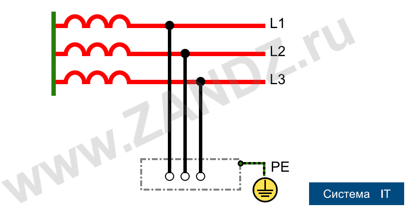
- And finally, let's proceed to the third kind - IT. This solution provides isolation of current-carrying parts of the power system from the ground. In some cases, grounding with the help of devices with high resistance is acceptable. Grounding of ECP is done separately. Sometimes, this option in the technical literature is called "systems with isolated neutral".
Details and features of the application of distribution networks, protective grounding
Having defined the classification of distribution networks, we will briefly define their practical purpose. And we start our consideration from TN type. Let's take TN-C as an example. It is one of the oldest and proven systems. It came to us from the Lenin plan of the GOELRO. Its advantages are economy and simplicity. The disadvantage is the absence of a PE conductor, which means an increased danger in the conditions of everyday life in terms of equipotential bonding and the absence of protective grounding in residential buildings (perhaps only "neutrallizing"). Receding technological system. It is not recommended for power supply of newly constructed facilities.
TN-C-S is offered as a transitional subsystem. In technical implementation, it is quite simple. The transition is simply carried out from the TN-C subsystem. But in the event of a serious damage to a PEN conductor, consumers of electricity may be in danger.
And finally, let's take a closer look at TT technologies. Because of the threats from electric shock, such a technology was banned in the USSR.
However, in modern reality, the Russian Federation achieved a great progress in the application of means of filling stations and RCDs. And this technology "got a second life", as a means of supplying electricity to drilling rigs, to building cabins and to other transportable and temporary facilities.
The grounding device of such a system is subject to increased requirements, which are reflected in the design and are prescribed in the technical specifications.
And now we come to the main goal of our narration - IT systems, on which we concentrate our main attention.
Distribution IT networks: historical retrospective, principles of construction, indicators of destination, areas of possible applications
In the historically foreseeable past (the beginning and middle of the 20th century), IT distribution systems had a dominant position in the countries of the Western Europe. However, for a number of reasons of economic and technical nature, they were abandoned and they switched to TN-technologies. If you think about why this was done, then such an example as the weak stability of IT networks for pulsed switching and lightning overvoltages and the higher cost of such solutions before the TN-technologies comes to mind. The exception is the Kingdom of Norway, where IT distribution networks are successfully operating and developing. There are reasons for this, among which we should mention the geographical location (northern territories with a small amount of thunderstorms, the northern lights do not count as they occur in the upper layers of the atmosphere), ubiquitous rocky ground (difficulties in constructing a highly efficient grounding system), low load on the country's energy system due to the lack of a mass nature of energy-consuming production, and due to a small area and the previous factor, large overflows of capacity (switching overvoltages) in the distribution networks. Nevertheless, let's leave the "Norwegian phenomenon" for now and ask ourselves: what is the niche applicability of this technology in the modern conditions of a post-industrial society? And to answer this question, let's look at the architecture of building an IT distribution network. In this technology, as we already mentioned above, the neutral is isolated from the ground or grounded through special devices with high impedance (sometimes in special cases a low impedance, less often arc suppressing circuit is applicable). At the same time, user's ECPs are reliably grounded, and this implies low leakage currents on current-carrying parts of the electrical installation and on the ground. Thus, in the event of an emergency - a ground short ircuit, the immediate disconnection of the power supply from the connected electrical equipment is excluded, the system continues to operate without interruption of power. It also excludes the appearance of an arc discharge and a "step voltage" with a high potential. It should be noted that this technology with a three-phase input allows you to connect the consumer in two possible ways: "triangle" and "star".
Having put the features of the construction of these grounding systems and their properties in terms of electrical safety into the base of the architecture peculiarities, we will determine the main indexes of the assignment of the grounding technology of IT distribution networks:
- it is safety for humans and animals, and also applicability in both ordinary household and unusual (extreme) conditions;
- increased protection from fires, explosions;
- simplified ability to mount these systems as a distribution network over existing power supply technologies;
- network scaling efficiency;
- simple network capacity management;
- damage detection system;
- stability of the network to multiple interphase short circuits;
- systems of protection settings (gas stations, SPDs, RCDs).
Based on the destination indexes, the sphere of possible applications follows. This is, first of all, medical hospitals (operational, resuscitation, etc.), where it is required to ensure high survivability and electrical safety of life support systems. Scientific laboratories, where sensitive electronic and computer equipment is used. Explosive production (enterprises of petrochemistry, wood processing, gas facilities, coal mines, etc.). Premises with high humidity (bath-and-laundry plants, swimming pools, livestock farms, etc.). Hydroelectric power stations and high-voltage substations, where the probability of potential step voltage generation is high. In this case, an overhead service technological power supply system is organized using IT-grounding technology.
And of course, the frequently asked question about the possibility of using IT-grounding in an apartment, an individual structure (a cottage, a holiday home, etc.), i.e. in domestic living conditions. We answer immediately - it is possible. And from the technical side, a separating transformer, sometimes called a safety transformer, plays a key role here. In this device, the primary winding is dead grounded and separated from an ungrounded secondary winding by a grounded metal shield and reinforced insulation, with a transformation ratio of 1, and the coefficent of efficiency reaches 0.98. All elements of the organization of IT-grounding in the housing stock are available for sale (safety transformers, modular grounding systems, grounding conductors, etc.) and are allowed for use. Moreover, safety transformers are produced in several versions (container and box types), which allows them to be installed both inside and outside the premises. In addition, transformer systems of separation type are equipped with a developed system of remote monitoring and diagnostics of the state of insulation and grounding.
At the stage of designing or upgrading the facility, it is necessary to agree on the design and estimate documentation of the construction project or to modernize the electricity supply system of the existing housing with energy inspection authorities. There are no special problems for individual construction. There are some difficulties with the housing stock of the old buildings, both in terms of the location of the installation of additional equipment, and the lack of grounding (TN-C technology).
All changes and upgrades in the energy supply system should be reflected in the technical passport of the house!
See also:
- Grounding. What is it and how to make it
- Lightning protection in a single-family house: standards calculations, examples
- What is a disspation array device and how it works?
- Useful materials for designers: articles, recommendations, examples
- Soil resistivity table
Related Articles:
 Protection of Fuel and Lubricant Materials (FLM) Storages with Floating Roofs Against the Static Electricity
 Five Most Dangerous Effects of Lightning


