
E. M. Bazelyan, DEA, professor;
Power Engineering Institute to the name of G.M. Krzhizhanovsky , Moscow;
recognized Russian expert in the field of grounding and lightning protection.
I think that those who love Internet won't be eager to read this article. You can just Google "heating temperature", and you will get at least a dozen files with calculation results or even a proposal to write a course work for a moderate price. You shouldn't be surprised since this task seems to be very simple. Looks like there are more than enough reasons for that but...
A simple estimate
No calculation problems are foreseen. You can just multiply the grounding resistance and the conductor length unit to the current square and exposure time to estimate the released heat. To do that, we need to know metal resistivity ρ and conductor cross-section s. And if current i(t) changes over time, you will have to calculate the integral for the current t exposure time.
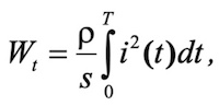
(1)
which is also rather simple. However, if you don't know calculus you can also avoid integrals. Guidelines for Lightning Protection SO153-34.21.122-2003 contain a specific energy table (W/R) for the rated lightning currents. Based on this parameter, the heat energy in a unit of the conductor length is determined by a couple of arithmetic operations:
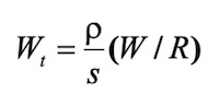
(2)
You only need to determine the weight of the conductor length unit for its specific density γ
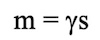
(3)
and multiply the obtained value to the conductor metal specific heat capacity c. As a result, a simple expression for the heat temperature can be obtained
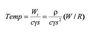
(4)
For example, for steel ( ρ =10-7 Oм м, γ =7800 kg/m3 , с = 482 J/(kg grad) ) with cross-section s = 50 mm = 5x10⁻⁵ m2 calculation for current 200 кА (W/R = 107 J/Ohm), rated for lightning protection Level I, yields a temperature increase of only 1060 (i.e. the conductor temperature at ambient temperature 25О С will be close to О С)
t is easy and very informative! You would only assess the provided estimate error. This error is based on unjustified simplification of the estimate model. Two essential well-known physical events are ignored: increase in metal resistivity in heating and limited propagation velocity of the electromagnetic wave in a metal. The latter limits the current penetration depth to a metal conductor (a skin effect). Thus, the actively used cross-section of the conductor loaded by the current is lower than the actual metal cross-section and it changes over time. Both reasons lead to the increase in real conductor temperature compared to the one provided above and used in the calculations over the Internet. It is important to understand the amount of the increase.
Temperature effect
With a relatively moderate heating ΔТ, typical of current collectors, the temperature ratio of the metal resistance growth can be taken as a constant value by recording ρ(t) = ρ0(1 + αΔТ). So, for steel
Considering the skin effect
The velocity of electromagnetic wave in a metal is determined by its resistivity and magnetic permeability, μ. In the simplest situation, for a flat wave, the efficient penetration depth for time t is estimated as
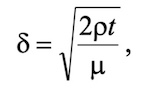
(6)
where in, in a general scenario, both resistivity ρ and magnetic permeability of ferromagnetic materials μ can change over time.
The algorithm of approximated computer calculation provided herein is based on the following simplifying provisions:
- the electromagnetic wave is presented as being flat in conductors of any cross-section;
- metal resistivity is included in the calculation to consider its temperature changes,
- the relative magnetic permeability is taken as 1 not only for aluminium and copper but also for steel because of its strong saturation in high lightning currents.
In quality terms, the structure of the calculation algorithm is similar to the one provided in the previous section. However, the calculation software, at each time calculation step, uses, in the formulas, the current values in the grounding electrode, its temperatures, metal resistivity and cross-sections, which is actually loaded by the current. To estimate the latter factor, expression (6) is used to determine the efficient current penetration depth to the current collector metal.
Note that in the taken simplified calculation where the skin effect is estimated while taking into account that the electromagnetic wave is flat, a real-life configuration of the current collector cross-section is not considered. Only cross-section is used as an initial parameter in the calculation. This way, we can simplify the calculation procedure, and the most essential point is to use estimate data for an approximate calculation of the current collector temperature as a circular conductor (reinforcement steel, copper or aluminum wire) and as a flat steel bus 30 x 3 or 40 x 4 mm.
Computer modelling analysis
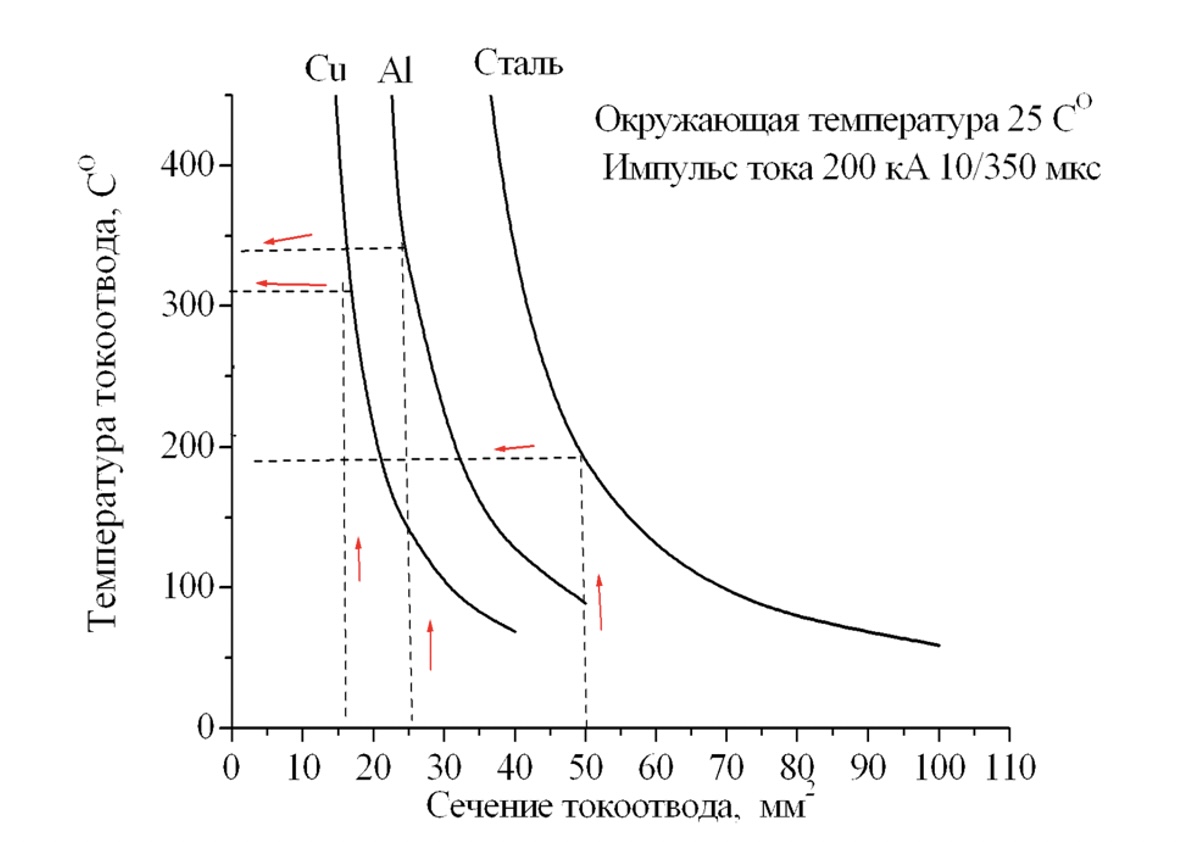
Fig. 1 Current collector temperature at the current 10/350 mcs, amplitude 200 kA vs. metal cross-section for steel, aluminum, and copper.
Температура токоотвода - Current collector temperature
Окружающая температура - Ambient temperature
Импульс тока 200 кА 10/250 мкс - 200 kA current pulse 10/250 mcs
Сталь - Steel
Сечение токоотвода, мм2 - Current collector cross-section, mm2
Estimated data in Fig. 1 have been obtained considering the temperature changes in metal resistivity and approximated consideration of the skin effect for the current 10/350 mcs, amplitude 200 kA (lightning protection Level I). Dashed lines in the diagrams show temperatures matching the rated current collector cross-sections provided in the lightning protection standard SO 153-34.21.122-2003. As expected
Now, in what conditions, can the fire risk become relevant? To provide a justified answer, you should initially track how the heating temperature changes in lowered cross-section values of current collectors to the left from the rated ones as shown in the diagram. Here, the estimate curve T(s) is distinctive by its sharp growth. Thus, e.g. for steel, decrease in cross-sectional area by only 20%, from 50 to 40 mm2, increases the heating temperature by almost twice, from 160 до 3050, , and in the aluminum current collector, 20% area decrease can heat the current collector to redness. At a temperature of about 6000 it is clearly dangerous in terms of fire for nearly any flammable coating of the building walls.
Note that the decrease in metal area by 20% is equivalent to the decrease in the current collector diameter by only 10%. It means you should treat the rated current collector cross-section with significant respect. There is no linear temperature vs. area relationship here. By no means should you ever risk by reducing the current collector cross-section at your own discretion even a little bit.
Now, there is also an important question: how often does the lightning current load a single current collector? They should always be at least two of them according to the Russian standards. So, a really dangerous situation will only occur in case of damage of one of the current collectors. To avoid this, current collector condition should be visually inspected. You should never ignore it.
However, in practice, we may sometimes see the advertisement of lightning protection systems with a single current collector. Fig. 2 illustrating the isolated lightning protection scheme for what has already been shown in our webinars. It has been taken from the information sheet of the isolation lightning protection system supplied by a foreign company. It seems like nobody remembers about the second current collector, which is understandable since the structure becomes very complex. This is one more drawback in addition to those typical of the isolated lightning protection.
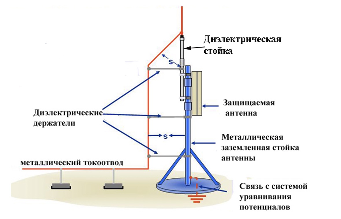
Fig. 2. Is there a second current collector in an isolated lightning protection system?
Диэлектрические держатели - Dielectric holders
Металлический токоотвод - Metal current collector
Диэлектрическая стойка - Dielectric support
Защищаемая антенна - Protected antenna
Металлическая заземленная стойка антенны - Metal grounded antenna support
Связь с системой уравнивания потенциалов - Coupling with the potential equalization system
If there are two or more current collectors
Now, let's talk about heating of the system comprising two current collectors. According to the existing standards, this number is a minimum. A twice lower current (100 kA, if you consider Level I lightning protection) flows along each current collector. Such current load reduction due to function T(s) non-linearity will sharply change the heating temperature (Fig. 3).
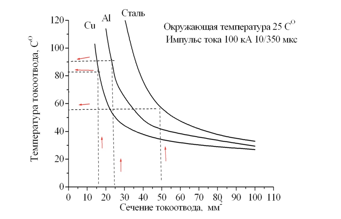
Fig. 3. Current collector temperature at 10/350 mcs, amplitude 100 kA vs. metal cross-section for steel, aluminum, and copper.
Температура токоотвода - Current collector temperature
Окружающая температура - Ambient temperature
Импульс тока 100 кА 10/350 мкс - 100 kA current pulse 10/350 mcs
Сталь - Steel
Сечение токоотвода, мм2 - Current collector cross-section, mm2
Considering the ambient temperature of 250, the temperature of steel current collectors will not exceed 550, and even an aluminum current collector will not be able to boil a thimble of water. Its temperature will be about 900 С. You can wrap the current collector up with a sheet of tissue paper. It will not ignite. An accidental error in current collector size made of non-ferrous metal here does not present any specific danger. At current 100 kA, curve T(s) reduces its steepness dramatically. Now, an erroneous reduction in the aluminum current collector area by 20% will increase its temperature by only 200. This will not cause any trouble, although it is better to avoid violating standard requirements, the more so Gostekhnadzor's representatives are on the alert.
It is also reasonable to ask which way is better: to distribute the current by two current collectors or to direct all current along a single collector with a doubled cross-section? Here, you should, once again, remember the function T(s) non-linearity. It works to the order of multiplying the number of current collectors. Computer calculations for 200 kA lighting current (rated by IEC and SO-153.21.122-2003) show that heating of two steel current collectors with the 50 mm2 ross-section is 35 degrees lower than that for a single collector with the 100 mm2 cross-section. A similar operation with increasing the rated cross-section twice for an aluminum current collector yields an even more marked difference, i.e. 50 degrees.
In any circumstances, the increase in the number of current collectors ensures a more significant effect than the similar increase in metal cross-section.
Here note that, in the majority of practical cases, the number of current collectors is determined not by their heating temperature but by electrical safety, mechanical strength, and potential equalization in a building with large dimensions, and the need to reduce interference in its interiors. Already with 4 current collectors, the temperature control loses its sense. In such conditions, the current collector with the rated cross-section (steel, copper, and aluminum) will heat by more than 150.
An issue of feasibility of mandatory spacing of current collectors from flammable decorative lining of buildings is reasonable. Unfortunately, I cannot answer it, but there is no specialist in lightning protection who can cancel such directions in the regulatory documents. So, there is nothing else, but to accept it and keep working.
An issue of insulation supports for current collectors will be of some consolation for you. According to the standard requirements, they should space the current collector from the flammable coating at the distance of at least 100 mm. The issue of insulation material is, fortunately, left open. It is reasonable to stop guessing but conduct laboratory experiments with modern plastics materials which are cheaper than metal, the more so you cannot find an unambiguous solution over the Internet. Thus, some of my colleagues in lightning protection (we will not say who exactly) are against plastics, without any justification or calculations. They say it will burn and cause fire. The statements located at their website are pretty dogmatic: the plastic should be prohibited. Our position is in many terms more preferred because the heating temperature has been calculated reliably. And not on average but for each individual current collector. For two current collectors made of either ferrous or non-ferrous metal with the rated cross-section, it does not rise above 1000.
The following figure demonstrates the capabilities of the current collector heated up to this temperature. I must confess that, as a joke, we have placed the current collector on a stearic X-mas candle rather than on a plastic holder. On the left, the candle photo is shown before the experiment, while on the right, after the experiment. The current collector was placed on the candle until it cooled down. Photos were not edited.
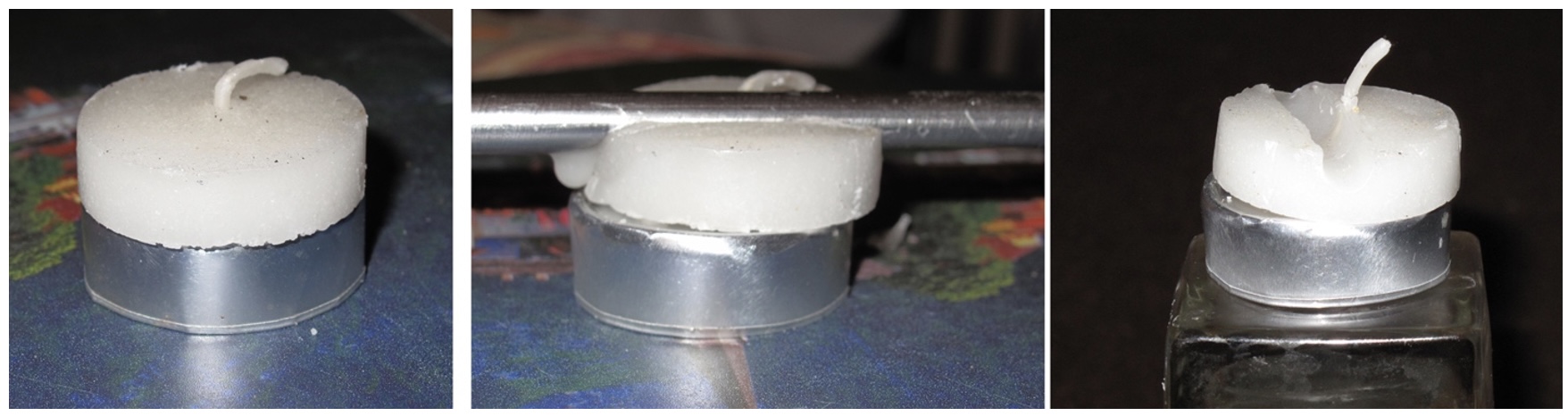
Fig. 4.
Current collector temperature 1000 С
Nothing but a slight melted trace was left. There was no fire either.
And now the experiment with a commercial plastic holder. The photo order in the figure has remained the same. Photos were not edited. And here,
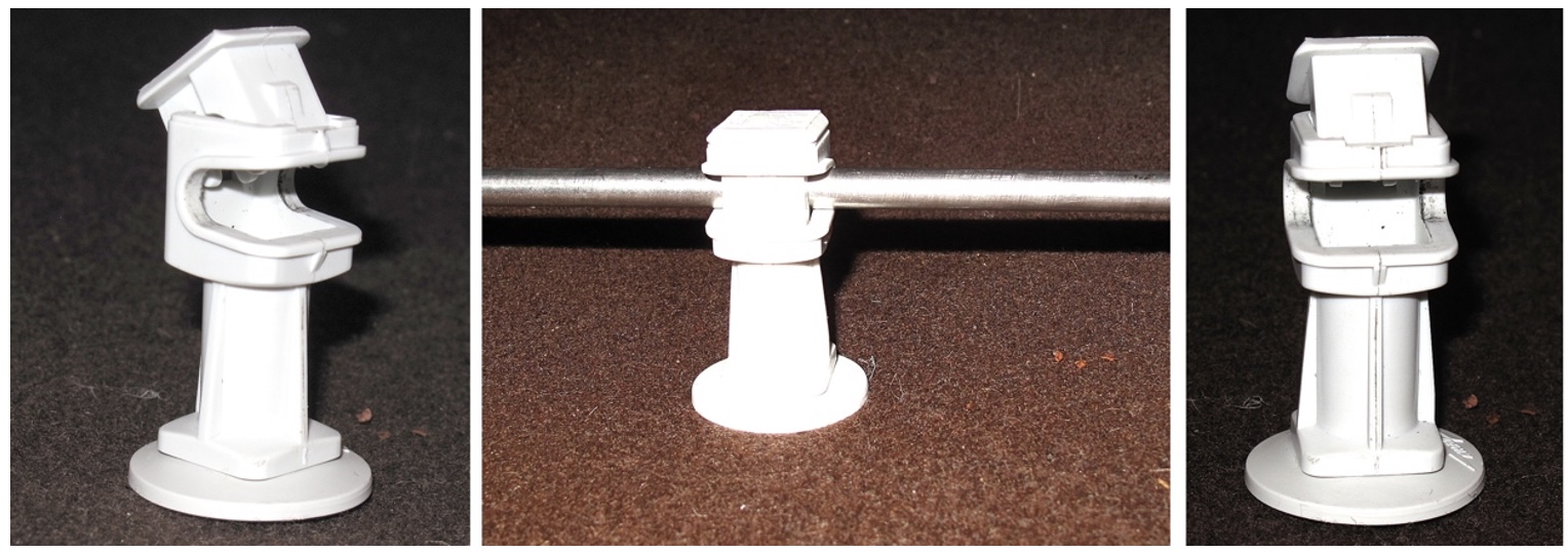
Fig. 4
Current collector temperature 2250 С
the current collector temperature, considering the candle experience, was increased to 2250 С. It is easy to make sure that the holder was not damaged. Even its colour in the point of contact with metal has remained the same. So, the plastics should hardly be ignored. For a large building, you need several hundred holders, and saving here is real. It is more so that it is hard to rely on the prompt change in the decision by regulatory authorities. They will not likely allow to place current collectors under the flammable coating.
Considering anomalies
This section is to consider currents of a positive lightning with an abnormally long wavefront (up to 200 mcs) and similar abnormally long tail (up to 2,000 mcs), which were rarely but still were recorded in field observations. Their probability is low. Within Russia, positive lightnings take about 10% of all discharges to the ground and only 5% of them are classified as abnormal. The total number of recordings of such lightnings is limited to several lightnings. Therefore, probabilistic estimates are hardly reliable. The Russian regulatory documents for lightning protection just like standard IEC 62305 do not mention such currents. Current 10/350 mcs, amplitude 200 kA is taken as a limit in terms of energy contribution. However, to provide guidelines for the designer, note that the transportation of abnormal current in two current collectors of the standard cross-section from any material leads to their heating to at least redness. The safe temperature around 100-1200 С may be provided by a system of at least 4 current collectors. If we solve a problem by the increase in current collector cross-section, then in order to reduce the heating temperture to about 1,000, the cross-sectional area of each of two current collectors should be increased at least 2.2 times compared to the rated one.
For security, we should repeat that the regulatory documents in lightning protection ignore positive lightnings with an abnormal current, therefore, the designer may ignore it.
The nature of the second anomaly is directly related to the current collectors themselves.
Bolt connections are usually made of steel. In a system of two current collectors, the limit lightning current of 200 kA, when it is divided in two paths, will deliver to each conductor specific energy (W/R) = J/Ohm; which, considering steel heat capacity c = 482 J/(kg grad), will provide heating up to 5000 of the clamp wit the weight of 530 g. Such heating is hazardous in terms of fire. Current collectors with bolt connections cannot be hidden under the flammable coating. Therefore, you should not reject welding, the more so steel welding is a simple operation compared to aluminum welding that requires argon.
I don't want to complete the article with scary calculational stories. The more so we don't have any notable reasons. In fact, you can hardly perform lightning protection for residential or administrative buildings in terms of Level I lightning protection. Most likely, Level III will be accepted with the rated current 100 kA (specific energy (W/R) = 2.5 x 10⁶ J/Ohm). Now, in each of two current collectors, the specific energy will reduce to 6.25 x 10⁵ J.Ohm, while temperature of steel clamp with the weight of 500 g will not exceed 1300 С. This is a safe temperature.
Any subsequent doubling of the number of current collectors will reduce the clamp heating temperature 4 times more, thus justifying the application of bolt connections.
It is left to estimate the frequency of dangerous overheating of current collectors. Here, you should rely only on small buildings with small wall length. This problem has no sense for residential, administrative, or production buildings with larger amount of current collectors. The current collector heating temperature is completely safe. Cottage with two current collectors is another issue. There is something to worry about there, even though the fire service specialists think that it is dangerous even when the current collector heats to below 1000. For such heating, when regulatory requirements are followed for the current collector cross-section, the 200 kA lightning should strike the building. According to the latest CIGRE data, the probability of such and stronger current is close to 0.2%. In case of typical cottage dimensions (if we do not consider the Galkin and Pugacheva's castle), the lightning attraction area is close to 0.006 km2, which, in Central Russia, leads to 1 lightning strike per 40 years of operation. Among them, the 200 kA lightning current will occur, on average, once in 20,000 years, while 100 kA lightning strike should be expected, on average, every 800 years. In such conditions, we have reasons to rely on the Prophet Elijah's kindness. In Russia, according to an old belief, he is the one who is responsible for the lightnings.
Related Articles:
 Methodics of calculation of SPD load currents
 Grounding resistance calculation is almost easy