Arrangement of grounding for electrical installations in the conditions when there is no open land is a very topical issue. In modern cities, housing development can be so dense that it is impossible to find an open ground area to provide grounding. However, this task is regularly set for designers and teams of wiremen. Let's consider basic methods to solve this problem for electrical installations of up to 1 kV, their advantages and drawbacks.
Using a building foundation
Effective regulatory documents for the arrangement of grounding systems recommend the primary use of natural grounding electrodes. According to the EIC, Rev. 7, item 1.7.109, it is allowed to use "metal and reinforced concrete structures of buildings and erections in contact with the ground...". Such structures may include, e.g. reinforced concrete foundation of a building and bored piles.
The best option is to embed grounding electrodes into the foundation during the building construction in accordance with GOST R 50571.5.54-2013 "Low-Voltage Electrical Installations". Then grounding will definitely conform to the effective standards and have terminals for connection. But in real life, often you have to deal with the foundation that was either built before this GOST has become effective, or it was built recently although without considering this document.
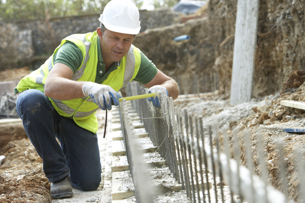
Many years of experience show that, in most cases, the reinforced concrete foundation is a good grounding arrangement. But there are exclusions. For example, increased requirements may be applied to the grounding system in terms of the current density. Then, the EIC Rev. 7, item 1.7.110 requires to connect foundation reinforcement bars by welding. If you make a grounding system in the building that has already been built, you have to find out how metal bars of the foundation were interconnected before they were filled with concrete.
The waterproofing layer may worsen the properties of a reinforced concrete foundation used as a grounding arrangement. The thickness of this layer usually depends on the environment aggressiveness. In terms of this parameter, the EIC Rev. 7 allows using reinforced concrete foundations located in weak and medium aggressive environments (item 1.7.109) as grounding. For the foundations located in strongly aggressive environments, the EIC Rev. 7 requires calculations justifying the possibility to use these structures as grounding (item 1.7.110). GOST R 50571.5.54-2013 "Low-Voltage Electrical Installations", Appendix C, sets that the use of the reinforced concrete foundation where waterproofing is provided by plastic sheets with the thickness more than 0.5 mm as a grounding arrangement is not efficient.
Thus, in some cases, the use of reinforced concrete foundation as a grounding arrangement may require the use of the design documentation for the building as well as additional calculations. Another problem is searching for suitable reinforcement bars, to which grounding wires should be electrically connected.
For the building construction in weak soils foundations made of bore piles are often used. This technology includes drilling wells with their subsequent filling with concrete. Note that such piles may both have or not have metal reinforcement bars. In case of presence of metal reinforcement bars, bore piles may be used to arrange grounding.
Utilities use
Any well-qualified electrician knows that you cannot use a water pipe located inside the building as grounding. But if the metal water pipe is located in the ground, then the EIC Rev. 7, item 1.7.109 allows its use to arrange grounding. The problem is that metal pipes located in the ground are now being replaced with plastic ones, which are not suitable for grounding. Modern metal plastic pipes are also unsuitable for this application since they are coated with polymer and therefore do not have an electrical contact with the ground.
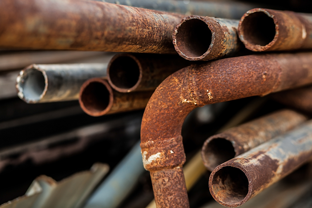
Another option also provided for by the EIC Rev. 7, item 1.7.109, is the use of a metal sheath of sheathed cables for grounding arrangement, if there are at least two such cables. And the use of the cables coated with aluminum sheath is not allowed for this purpose. Note that we are talking about the metal sheath of cables, i.e. external surface contacting the ground. This provision was relevant in the times when power cables in lead sheaths were widespread. But today’s sheathed cables usually have a strong polymer coating, instead of a lead one, on top of the metal sheath, which does not conduct the electrical current. Thus, this option for the grounding arrangement in current conditions is not always applicable.
Location of a grounding system at a significant distance from the electrical installation
To solve the problem, it is possible to place the grounding system in the location where an open ground is available. The EIC Rev. 7, item 1.7.106 permits this approach if, at the distance of 2 km from the electrical installation, there are places with lower soil resistivity than in the immediate vicinity to the protected equipment.
The absence of space for the grounding system in a large city is not a reason for placing the grounding electrode at a distance according to the EIC Rev. 7, although it may happen that at the place with an open ground, the soil resistivity will actually be lower. But in real life, problems will occur related to the fact that with the increase in the wire length, its inductance grows. For the modern electrical grids characterized by high level of pulse and high-frequency interference, this may lead to failures in operation of complex digital equipment. Finally, in a densely-populated city, it is hard to find a place to lay the cable to grounding electrodes.
Modular grounding
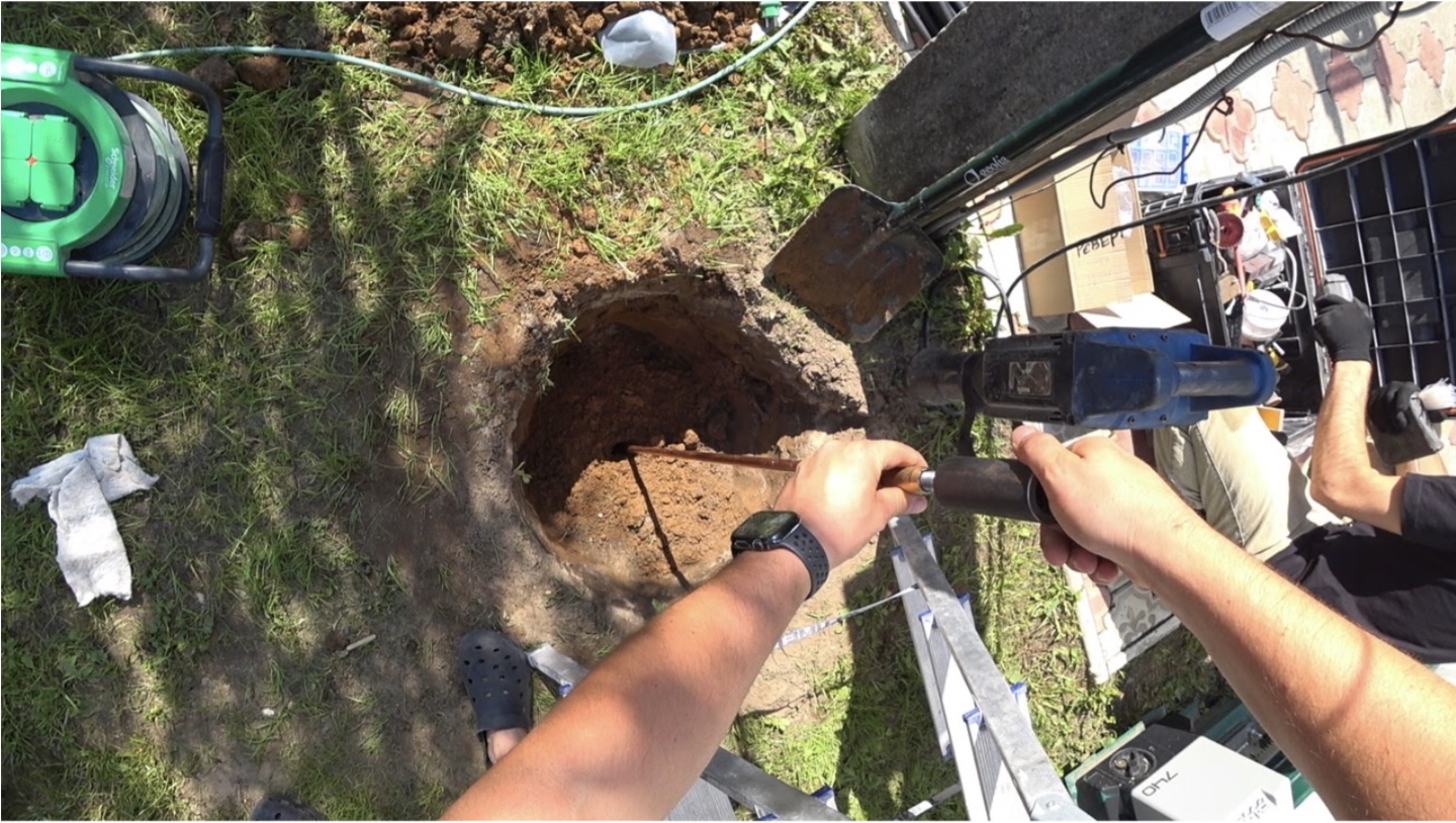
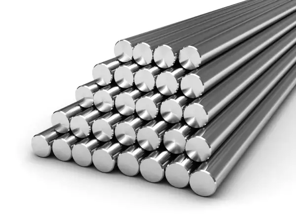
Usually we can find a small area of an open ground, but it is insufficient for even a conventional three-electrode grounding system. Then the problem may be solved by using a deep modular grounding. It is a rod with the length of up to 30 m assembled from separate modules of up to 1.5 m long. Due to a great depth, such grounding provides the required parameters when using only one electrode. Moreover, typically the rod reaches the ground water level which dramatically improves the efficiency of such grounding.
Modules of up to 1.5 m long can be conveniently stored and transported. At the location, they are connected with threaded couplings which provides for their secure electrical contact. The edge module is equipped with a special termination that provides deepening of the rod in a hard soil. The rod is nailed down with a hammer drill or a powerful perforating device equipped with a special attachment. As the rod enters the soil, new modules are added to it using threaded couplings. One employee can perform this task.
Whenever required, a deep modular grounding may be used in the locations with no open ground. For example, bore a hole in the asphalt and nail down the rod into the soil under the surface. To provide safety and good appearance, a pit is provided where an inspection well is installed which allows for servicing the grounding system. The lid of this well is flush with the soil. Another option is to drill a hole in the basement. If there is soil under the concrete flooring, we can also nail down the grounding rod there.
Before installing a deep grounding system, you should make sure that, at its further location, no utilities or other facilities which can be damaged by the rod are present.
The ZANDZ brand offers multiple sets of a modular grounding, which can be used to create a deep grounding arrangement. For most applications, modules made of steel coated with the copper layer are suitable. And copper coating is applied by electrolytic deposition, which ensures its high strength. ZZ-000-015 set allows assembling a rod of up to 15 m long, while ZZ-000-030 – of up to 30 m long.
When the grounding system is created in an aggressive environment, in the former locations of industrial zones or irrigation fields as well as in the locations characterized by high moisture, improved corrosion resistance is required. Then the sets with the modules fully made of stainless steel are suitable ZZ-000-115 set allows assembling the rod of up to 15 m long, and ZZ-000-130 – of up to 30 m long.
To provide the convenient access to the rod top, we can use a special control/inspection well ZANDZ ZZ-550-002 made of a durable plastic.
Conclusions
The use of the reinforced concrete foundation as a grounding system is a reliable and efficient method. However, it may require the study of the foundation's design. For old buildings, it is sometimes hard to find the respective documents. Moreover, highly qualified specialists may be needed to perform calculations.
The use of water pipes placed in the soil as well as metal cable sheaths as grounding arrangements is an obsolete method. Even though the existing water pipes or cables at the facility allow its use, in future, they will be replaced with the modern ones.
Location of grounding to a significant distance is not the best option, especially in the conditions of a dense building development.
The most versatile method is the use of a depth modular grounding. If you install it as per the guidelines, conformance of the resulting grounding to the standards provided in the EIC Rev. 7 is achieved nearly in all cases. Documents will be needed only for the utilities located in the soil, and you will not have to make complex calculations. Therefore, this solution is convenient for the business of various scale: from a small team of wiremen to a large construction company.
Related Articles:


