Task:
Facility: a sewerage pump station with an on-ground reservoir.
Soil: sand clay, sand.
Soil resistivity: 300 Ohm*m.
It is required to calculate external and internal lightning protection and earthing with resistance not exceeding 10 Ohm, offer a solution to protect building and electrical equipment against surges.
Solution:
Protection of a sewerage pump station (SPS) against lightning strikes and their effects is made according to the following regulatory documents: the EIC, Rev. 7, Chapter 1.7, SO 153-34.21.122-2003 «Guidelines for Lightning Protection of Buildings, Structures, and Industrial Utilities (hereinafter referred to as SO) and RD 34.21.122-87 «Guidelines for making the lightning protection of buildings and structures" (hereinafter - RD).
The station is classified as conventional in terms of facility lightning protection. According to RD, the pump station conforms to zone B, and according to SO its protection zone having a protection ratio 0.9.
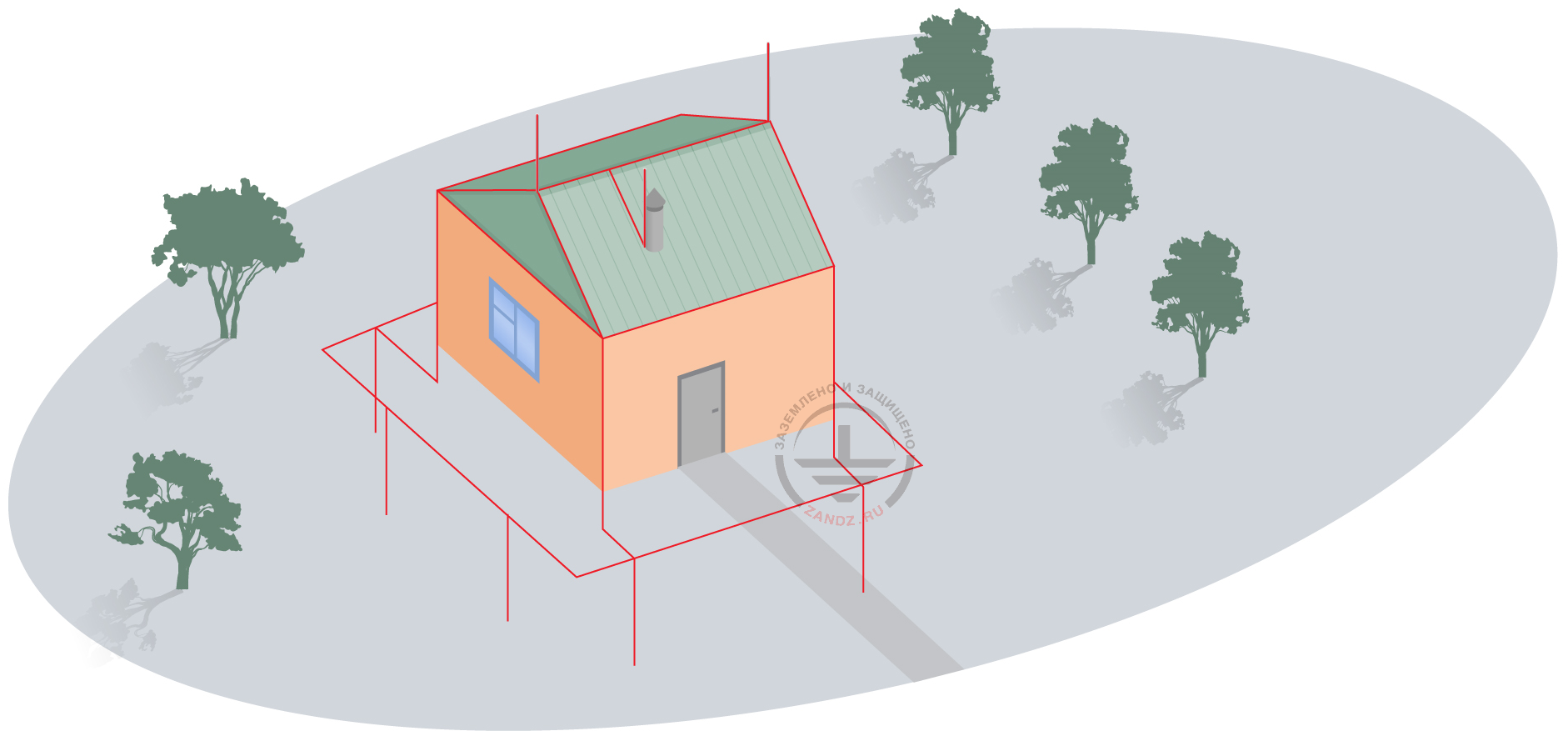
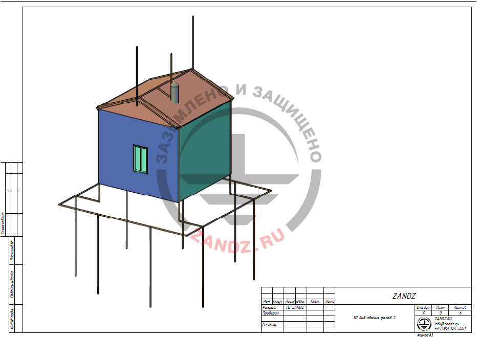
Buildings and electrical equipment are protected against lightning discharges and surges using lightning arresters, current collectors, and ground terminals. The lightning arrester is a metal rod exceeding the protected facility, which catches the lightning discharge. The generated discharge current is transported along current collectors in several shortest paths to the ground terminal.
Metal rods secured to the roof ridges using a clamp GL-11521SS are used as lightning rods.
The set of arrangements ensuring compliance with the lightning protection requirements is based on the following solutions:
- 1. 2 m ridge lightning rods (GL-11521SS) secured using clamps GL-11525 are installed on the bow window ridges. Lightning rod is secured using clamps ZZ-203-002 on a vent pipe (distance between the feet is up to 1 m). They are connected to the current collector using a clamp ZZ-202-001.
- 2. Current collectors are made using a conductor, which is made of a copper-plated steel and has a diameter of 8 mm, coating thickness 70 mcm (GL-11149).
- 3. Current collectors are installed using a clamp GL-11747A on the roof and GL-11703A on vertical surfaces. Clamp installation spacing is 0.8 to 1.0 m.
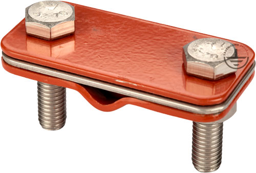
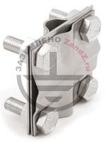
- 4. The universal GL-11551A clamp is used to connect rolled products over the length and in assemblies.
- 5. All metal elements located on the roof are connected to current collectors using clamps GL-11514 or GL-11545A.
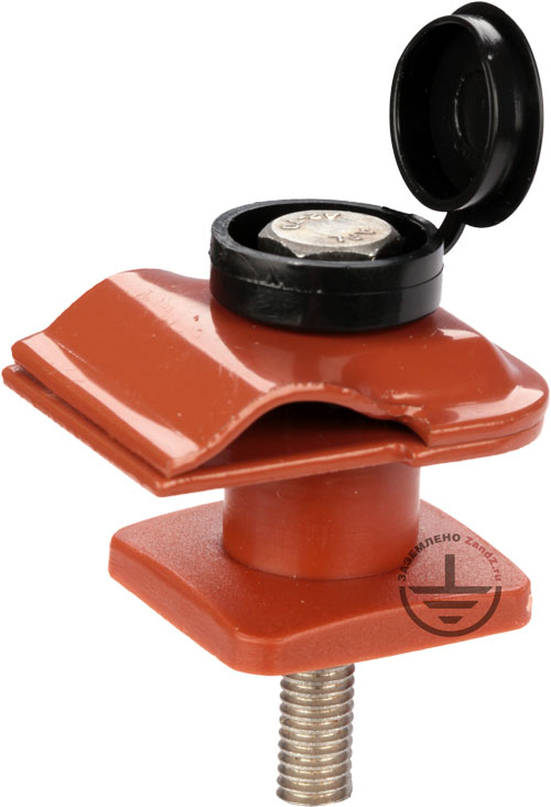
- 6. 8 x 3 m vertical electrodes combined by a grounding conductor, and a steel copper-plated bar 30 x 4 mm (GL-11075) can be used as a ground terminal. The distance from the ground terminals to the facility is at least 1 m.
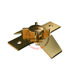
- 7. Current collectors are connected to the grounding conductor using clamps GL-11562A.
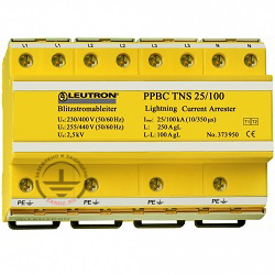
To protect the electronic equipment of the pump station and other electrical equipment from pulse surges caused by lightning strikes or grid overvoltage, the design provides for the protection against surges at the building entry by installation of a pulse surge limiter of Class 1+2 (Main) Power Pro BC TNS 25/100 LE-373-950.
Calculation of a ground terminal
According to the EIC, Rev. 7, item 1.7.103 total dissipation resistance of ground terminals (including natural) of all repeated earthings of the PEN wire of each high-voltage line in any season of the year should not be more than 10 Ohm, respectively, with linear voltages 380 V of a three-phase source or 220 V of a single-phase source.
Results of the earthing calculations performed by using the software developed by OAO Krzhizhanovskiy Energy Institute (OAO ENIN):
300 Ohm m is taken as an estimate soil (sand clay) resistivity.
Let's preliminarily define 4 x 3 m vertical electrodes drilled into the ground at the depth of 0.7 m.
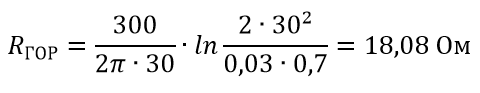
Resistance of a horizontal electrode:
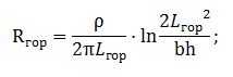
Гор - Hor
ρ is soil resistivity, Ohm·m;
b is strip width of a horizontal electrode, m;
h is a laying depth of the horizontal mesh, m;
Lhor is total length of the horizontal electrode.
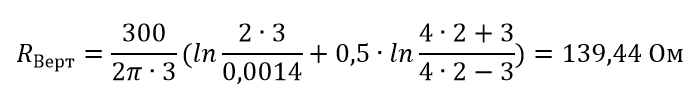
Vertical electrode resistance:
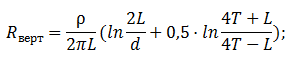
Верт - Vert
ρ is soil resistivity, Ohm·m;
L is total length of the vertical electrode, m;
d is vertical electrode diameter, m;
T is a embedment – a distance from the surface of the earth to the ground terminal system, m:
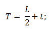
where t is deepening of the top of the electrode, m.
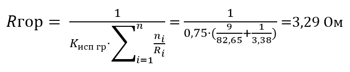
Full resistance of a ground terminal:
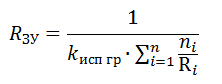
ЗУ - GA
Исп гр - Util
where n is number of sets
kutil is utilization ratio;
Гор - Hor
Верт - Vert
Ом - Ohm
The calculated resistance of the grounding arrangement is 16.12 Ohm which exceeds the required value of 10 Ohm; let's increase the number of vertical electrodes by 4 pcs.
Then,
Rga is 8.87 Ohm; and let's finally calculate the number of 3 m vertical electrodes, which is 8 pcs.
List of required materials:


Appendix: design in DWG and PDF formats

Need a design of earthing and lightning protection? Order now by contacting ZANDZ Technical Center!
Related Articles:
