The fifth webinar of the series “BIM Design: From Fundamentals to Practice”
Webinar text. Page 2
Fast navigation by slides:
Page 2:
3. Utility systems (MEP)
4. Questions and answers
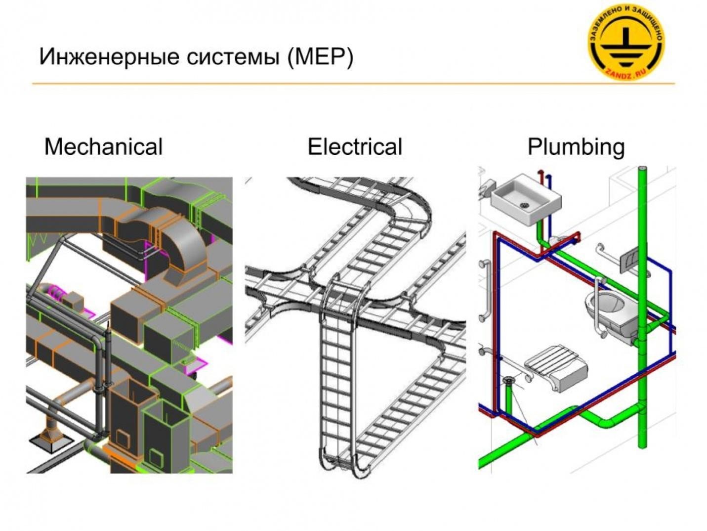
| Инженерные системы (МЕР) | Utility systems (MEP) |
– In addition to Revit Structure and Revit Architecture, there is also Revit MEP; MEP means Mechanical, Electrical, and Plumbing. We will look into all three sections. Initially, we will consider the creation and adjustment of tracing for these systems.
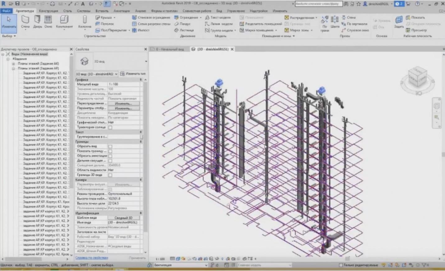
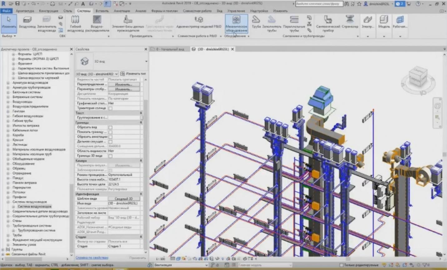
– The following project is provided for it. I will launch Revit. This project was created in Revit. It is for heating and ventilation. As I have already said, two sections are provided here. And the entire documentation was produced from this model. What do we have? All elements are divided into two types: loadable families and system families. What are the system and loadable families? The system families are all elements of different service runs, such as air ducts, pipelines, trays, etc.
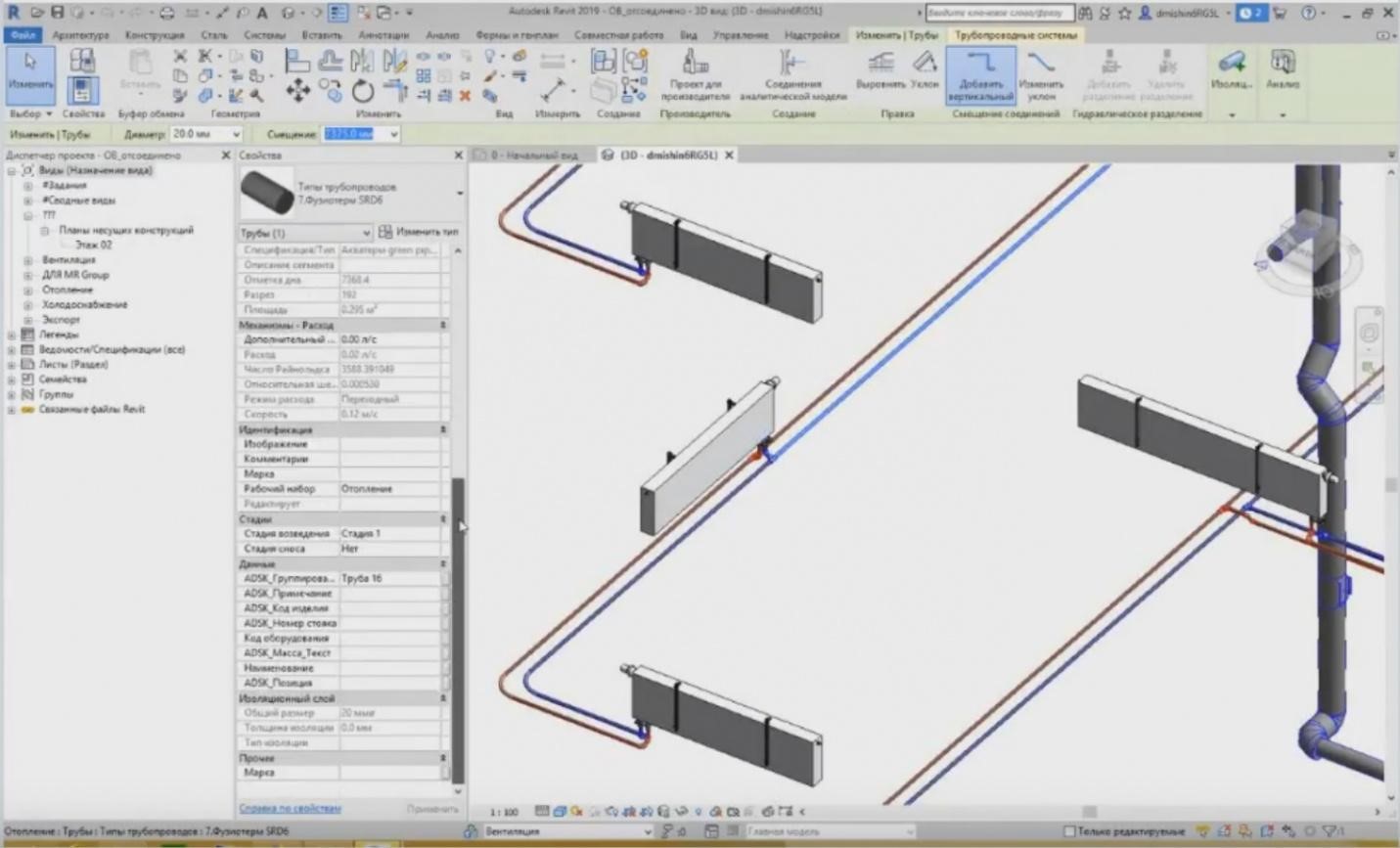
– I can highlight this pipe and view its description. The type properties show that it is a system family, i.e. pipeline types. We have the pipeline types. In addition to them, we also have air ducts; they also belong to the system families. If we look at it, we will see “System Family: Air Duct”.
– In addition to the system families, there are also loadable families. The loadable families are typical families of various equipment, fittings, etc. They are also provided here. For example, the heating equipment family is the equipment and it is a loadable family. Some libraries may be downloaded from Internet, but they are mostly developed by the companies for their projects that produce these models. We can go to this family and look through all of its characteristics provided here.
– In addition to the equipment, what more loadable families do we have? The loadable families also include connectors for utility systems. These are the so-called fittings. Thus, they are presented for the pipelines; we can also see their names and some characteristics.
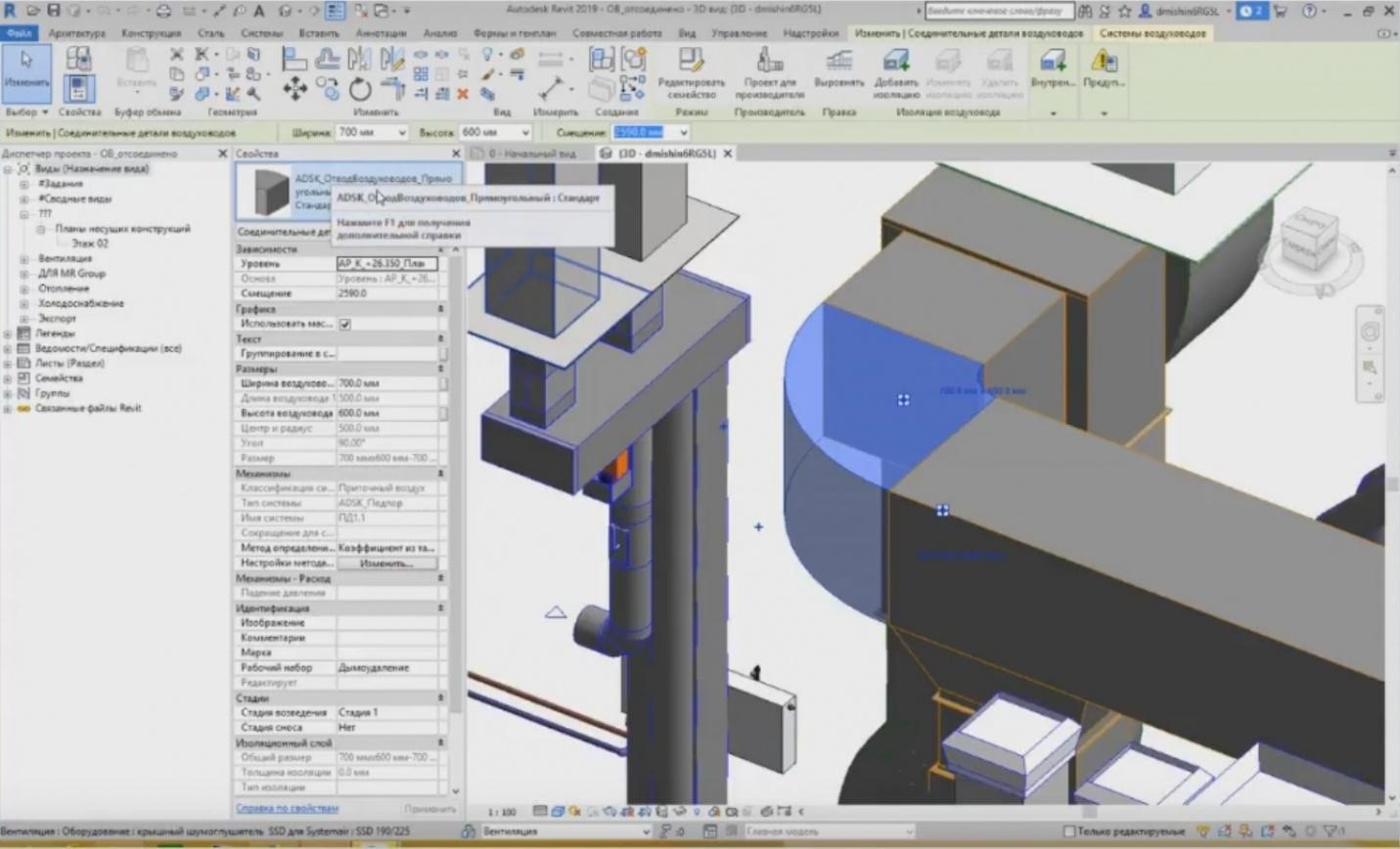
– As well as for the ventilation. This is a rectangular channel of the air duct. We can also see their characteristics. These families are also created separately as loadable; they are uploaded to the project and added into the tracing settings properties of particular utility systems.
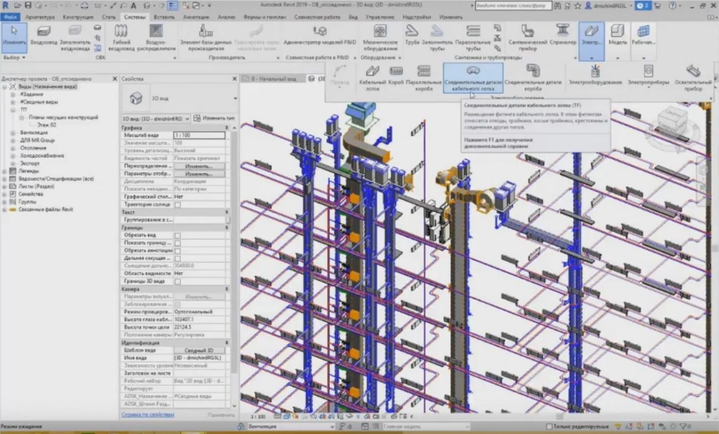
– Where are the settings of the utility system tracing? Where are they stored? If we go to the system tab on the toolbar, you can see that several sections are provided there. The first section is heating, ventilation, and air conditioning. Then, there is a section of the manufacturer's project; we will not settle on it now. After that, the equipment is provided separately, and then we have sanitary equipment and pipelines, i.e. everything that is associated with the pipes. And the last point; we do not have enough space on the screen for it, this is the electrical equipment (trays, electrical equipment, illuminating devices, etc.).
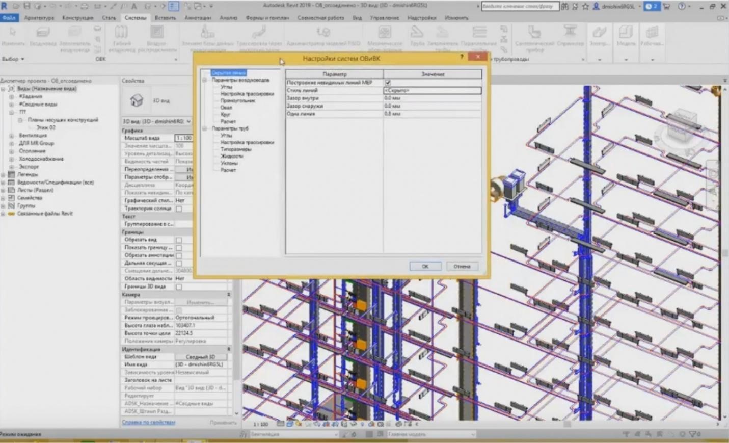
– Each tab contains a small arrow in the corner of each section. When you press the button, the settings of the utility systems appear. This is a window wherein we set what we need for the project. The first is various visual images of hidden lines, various gaps, i.e. the stylizing features.
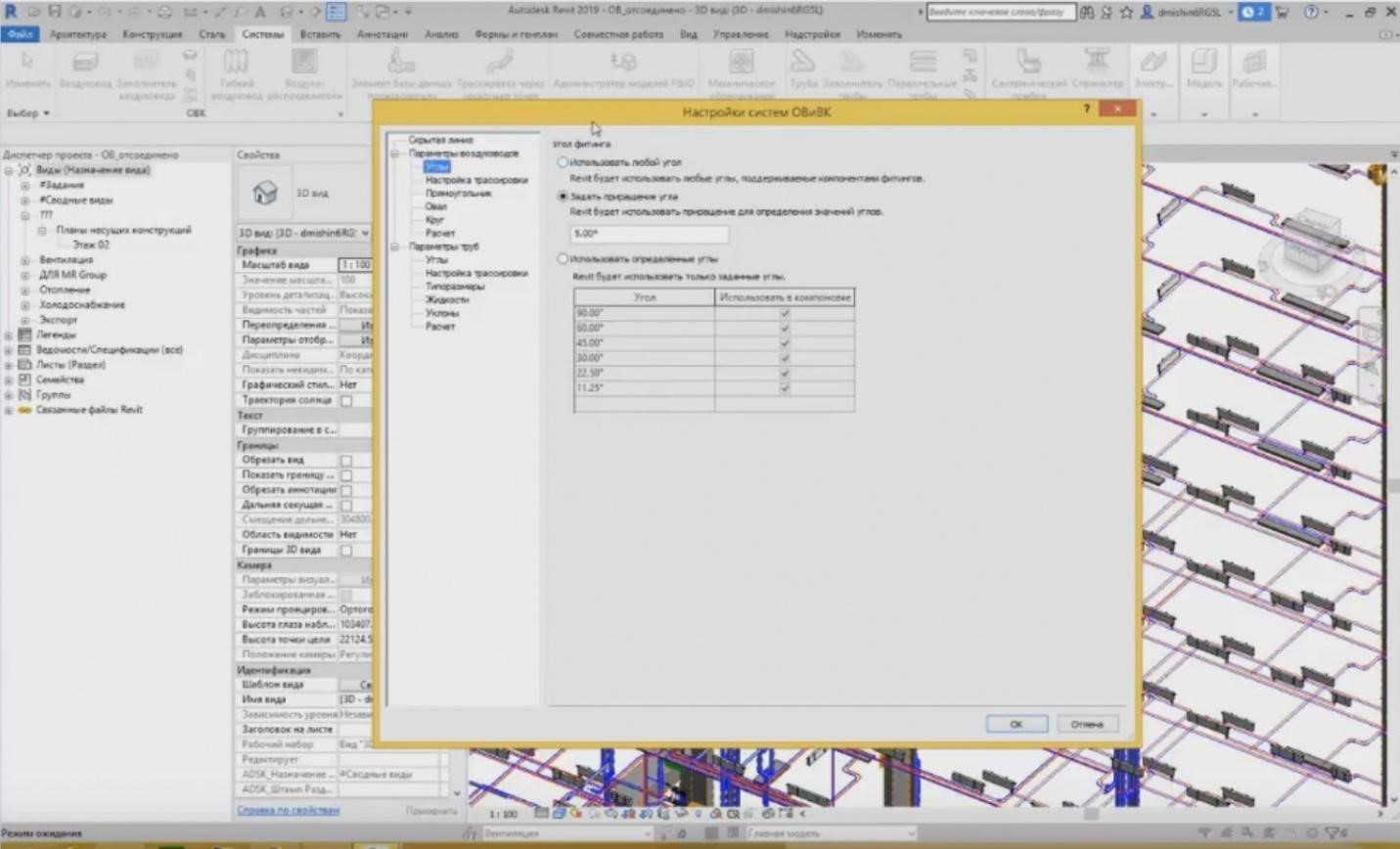
– Then, we have the parameters for the air ducts and pipes. Here, we define, at what angles the connections will be formed. We may set any angle. We may define an increment of 5º, we may set any particular angles and choose the ones we need from the list.
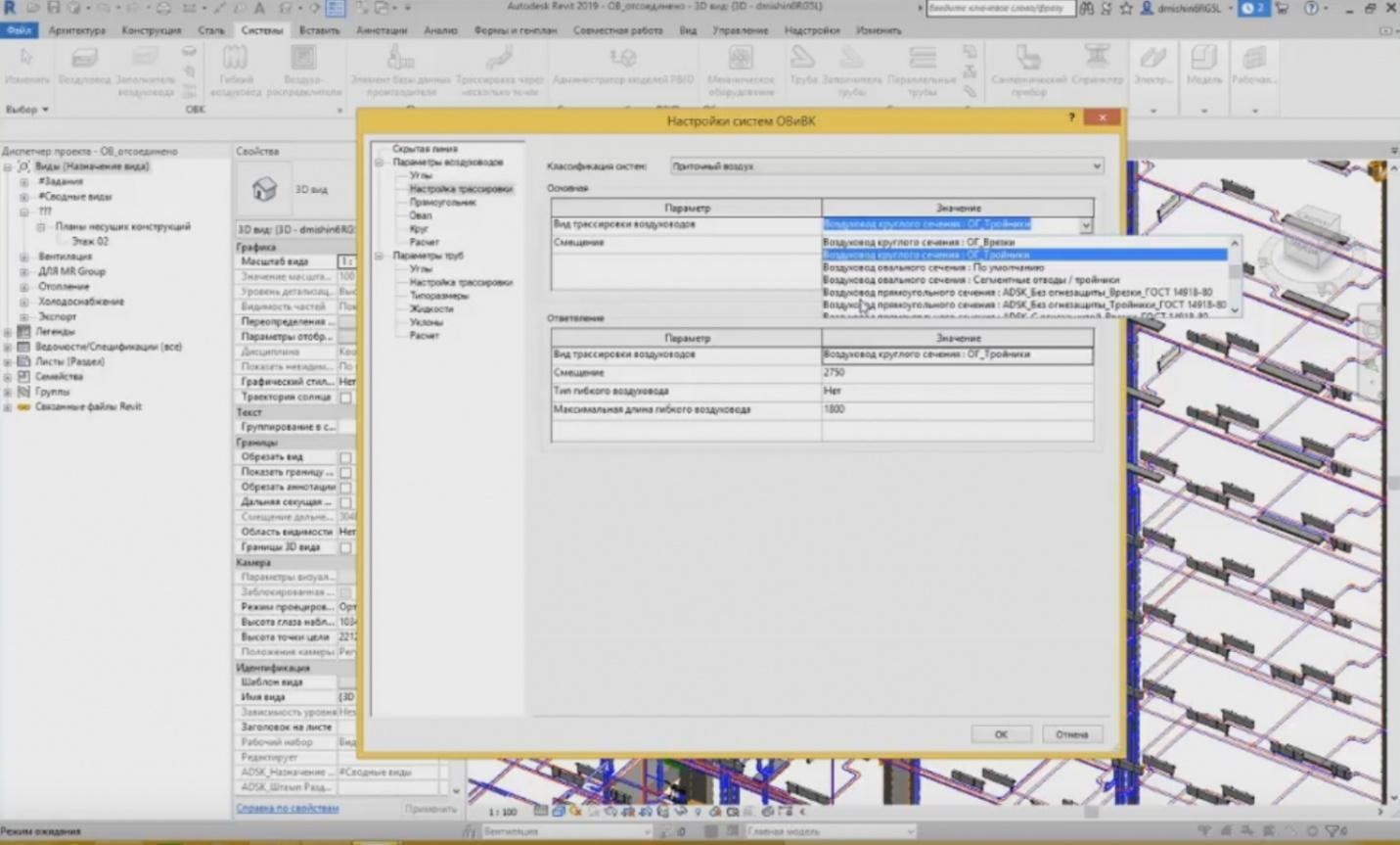
– In the tracing settings we specify what views of the air ducts will be created as basic views and as branch views. And the marks, i.e. at what marks they will be created. We also choose them for each system: plenum ventilation, recirculating or exhaust air.
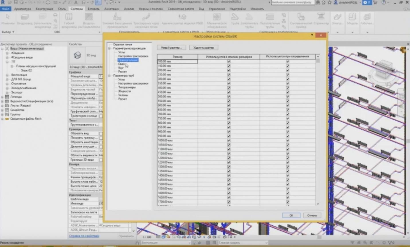
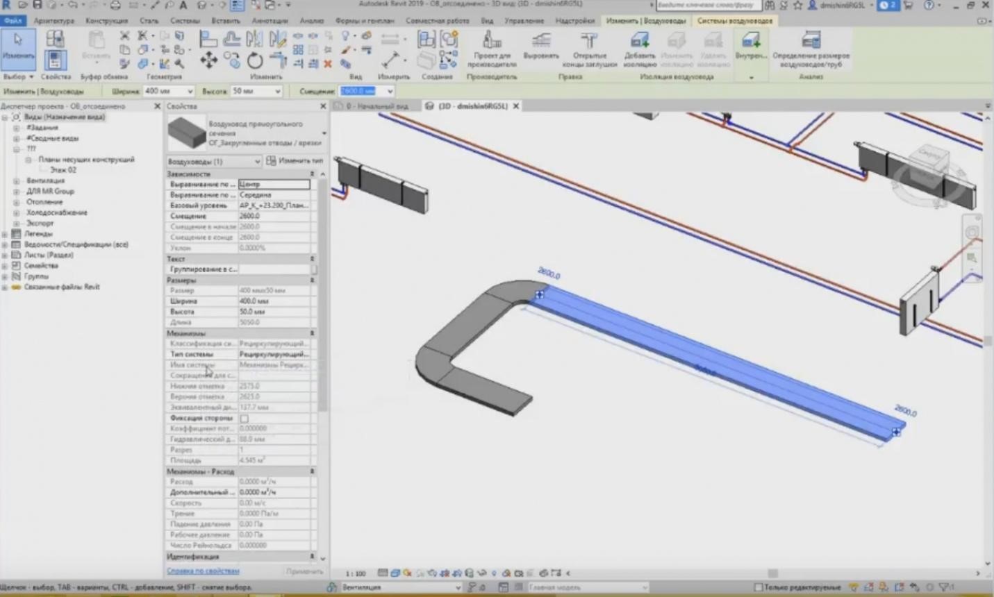
– Moreover, we have settings for various air ducts: rectangular, oval, and circular. All system air ducts are classified into three subcategories. And we define the dimensions of these air ducts. All dimensions are provided here, from 100 mm to almost 2.5 meters with a step of 50 mm. If we need a new type of the air duct, we can create a new dimension and enter it, e.g., 525 mm. It will appear here. Then, we can use it in our project. The same is true for the oval and circular air ducts.
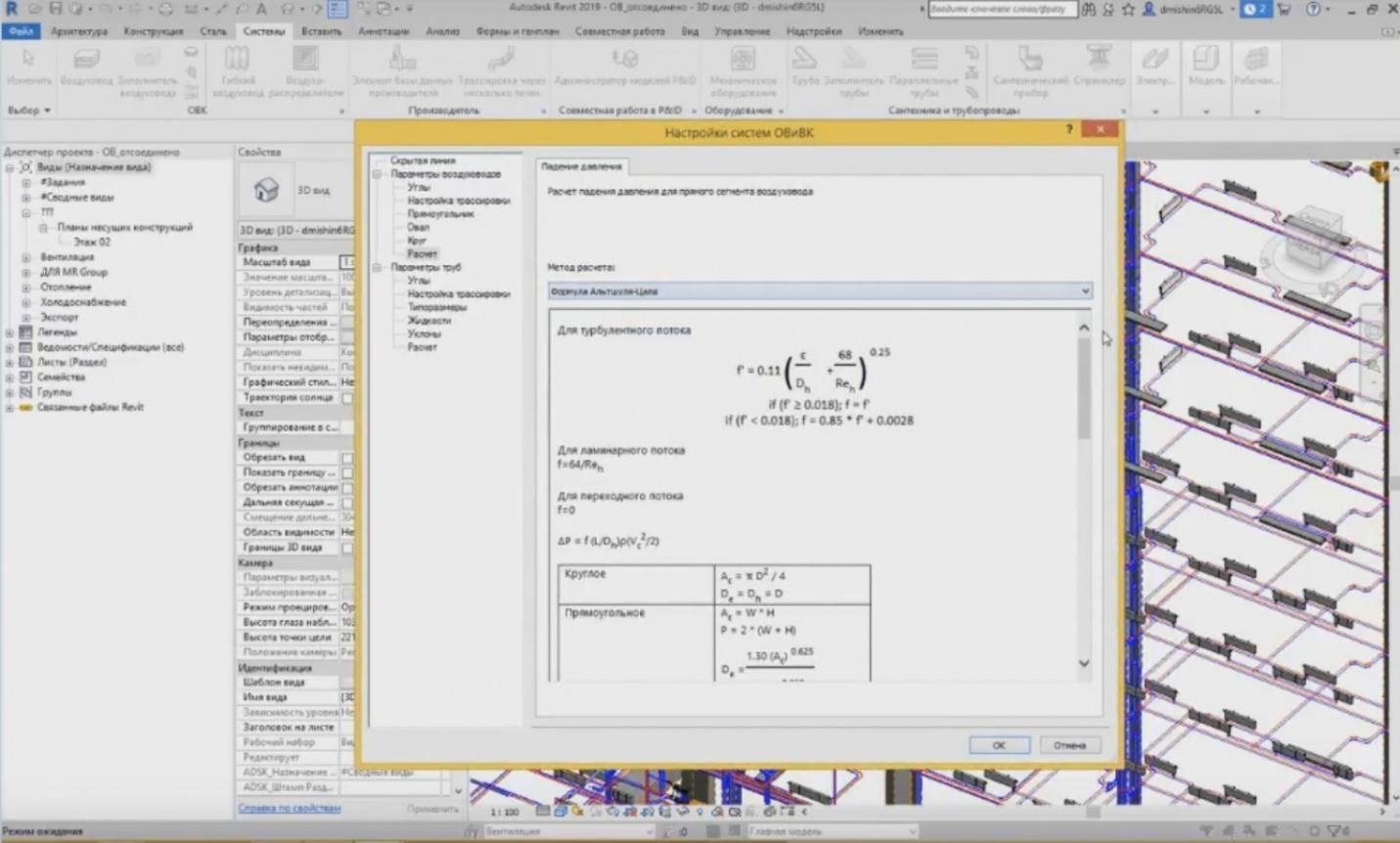
– In the “Calculation” tab, the calculation methods are provided. Unfortunately, as far as I understand, and according to the methods of the designers' work, they do not like these calculation methods.
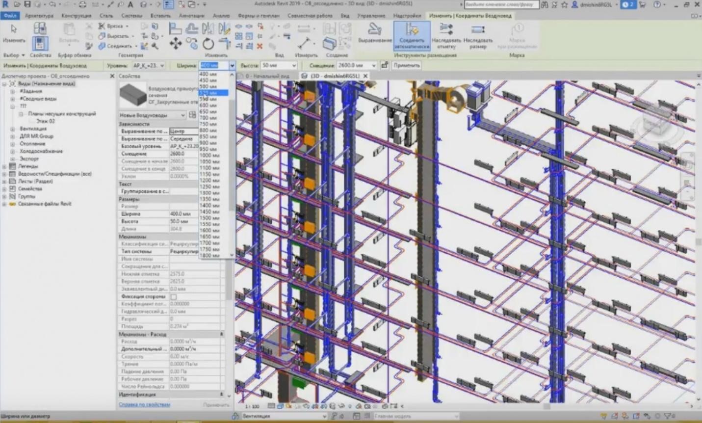
– The first tab includes the parameters for air ducts; so, I have created a new rectangle of 525 mm, and when creating these systems, I can specify it as a dimension. When creating a new type of the air duct, I choose the level where it will be created, then choose the width and the height of the air duct, and the new dimension appears, 525 mm.
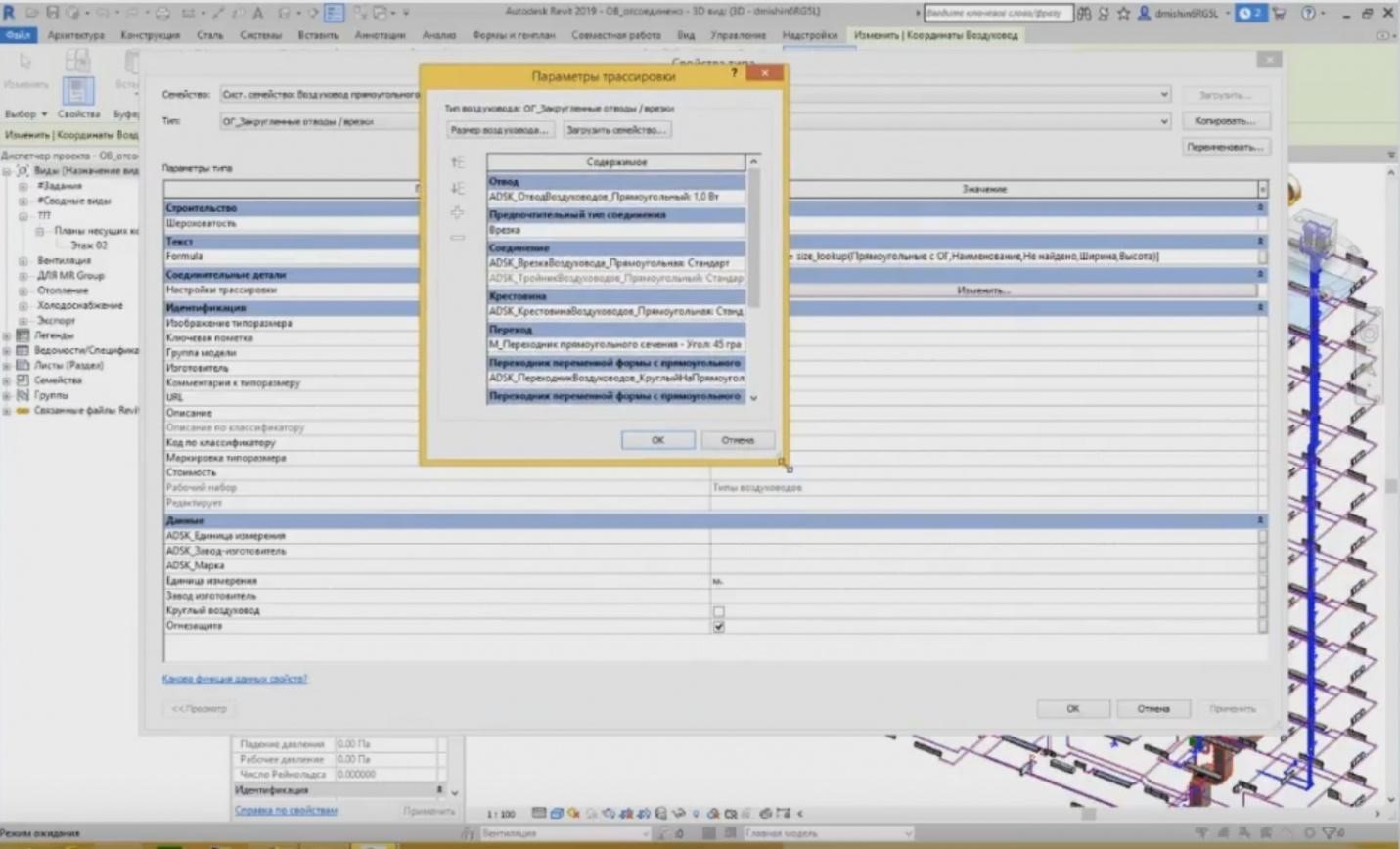
– In addition to defining the width and the height, we can also set the connection. How will our system function? What connections will be assigned? To do this, we can go to the type properties of a particular air duct, and the type properties contain the so-called “Tracing Settings”. We specify there, what types of connecting elements will be engaged upon creation of a utility system. We choose the channel for our rectangular air duct. In this list, different channels are provided. In addition to this, we can add new positions, which will be used for creation, for example, not only this rectangular but also the rectangular having a smaller curve diameter. Then, in addition to the channel, we can choose the connection type: either a T-shape pipe joint, or a tie-in. And the respective connection: either a tie-in family, or a T-shape pipe joint family. Then, “Cross-bar”, “Transition”, and all the other elements we need, can be specified here.
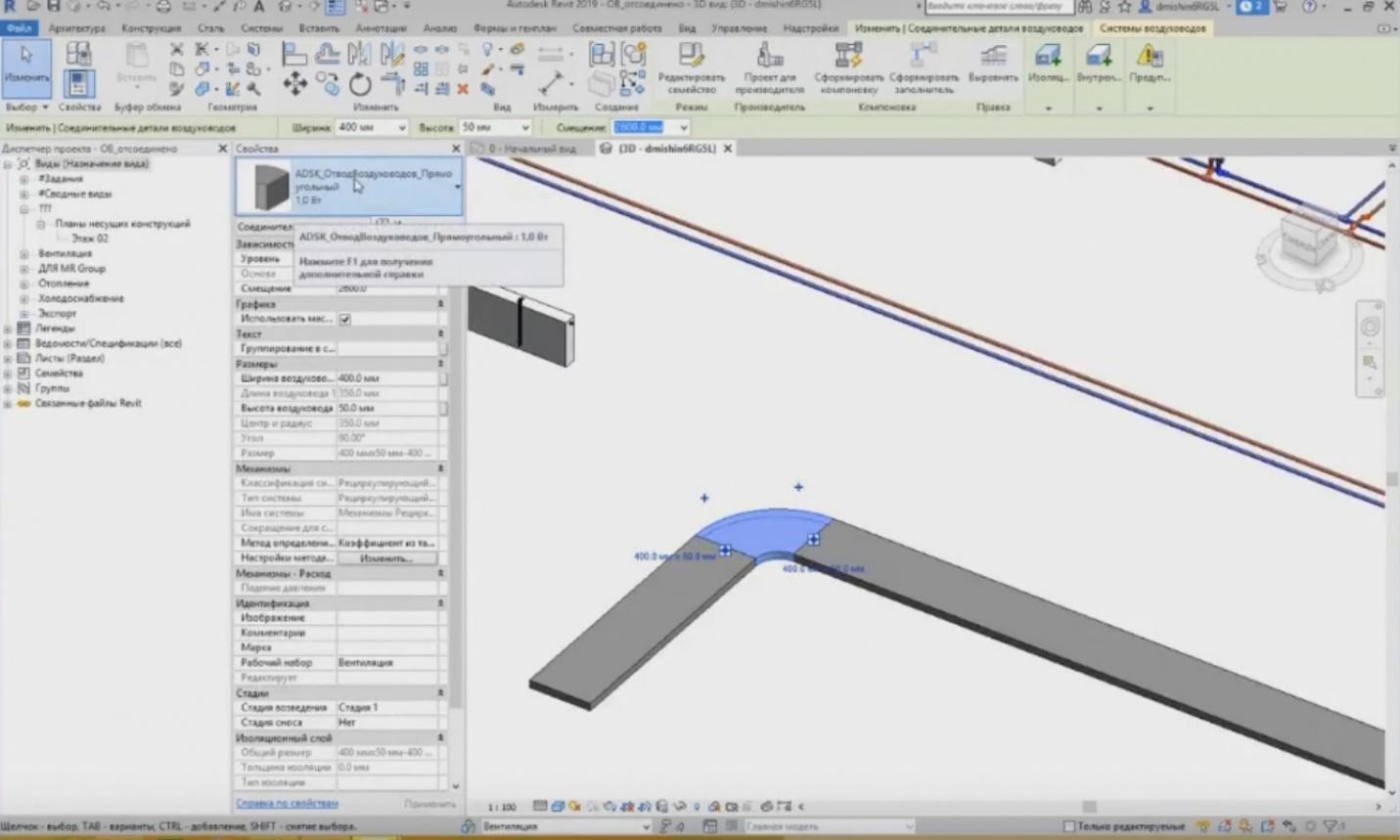
– And when we create a connection between air ducts, e.g., when I create one air duct and draw the second one, such connection element is created automatically. It is the one that was specified in the tracing settings.
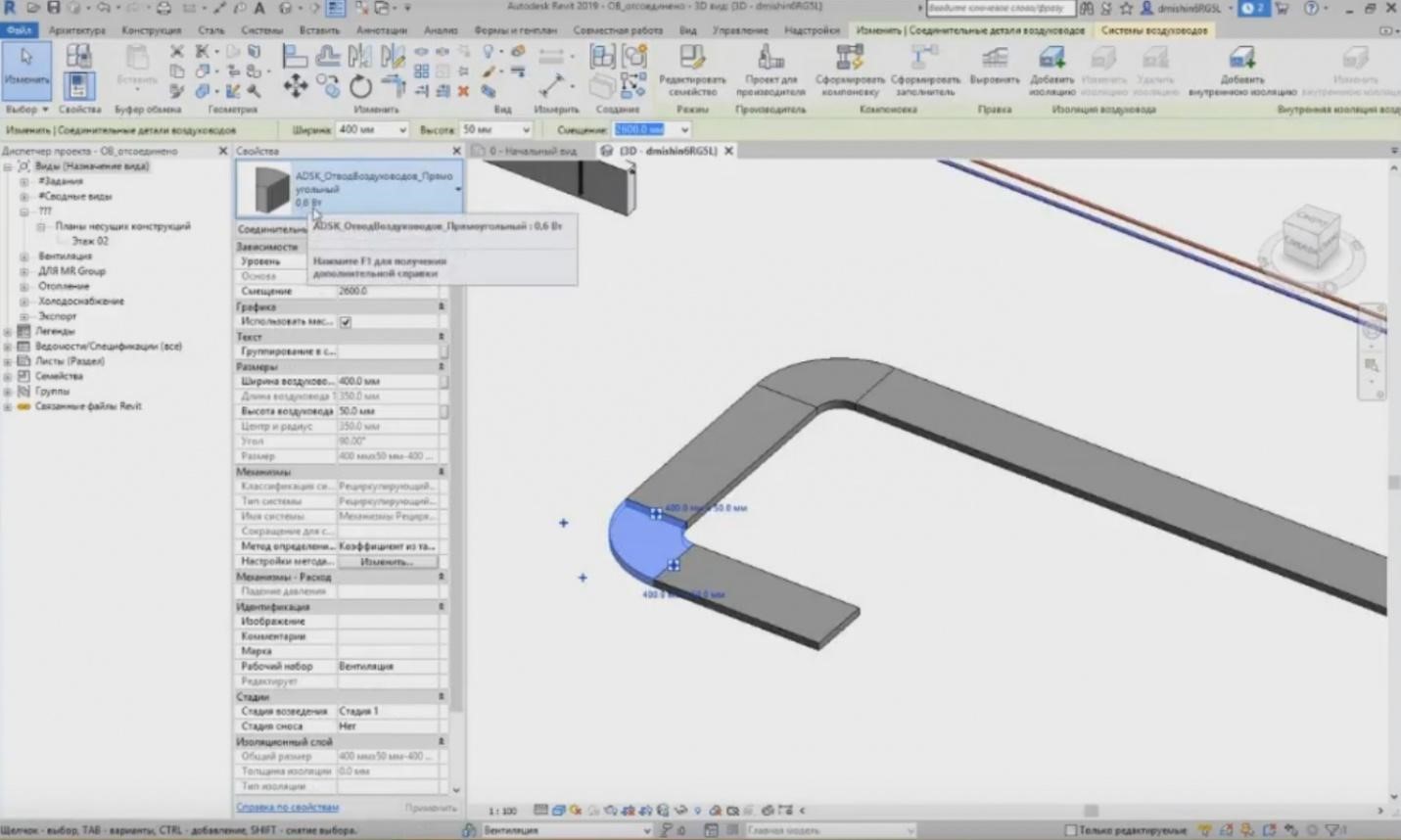
– Thus, if I need another one, then in the tracing settings, I can change this type to, e.g., a new 0.6 W, and press OK. The elements that have already been created will not change. They have remained the same. But when you create new elements, new types of connecting elements will be created. You can see that the type has changed to 0.6 W.
– What do we have in addition to the tracing settings? We can set certain classifications for the utility systems. Classification of the utility systems is available during the air duct creation. The settings of the air duct contain such parameters as classification of the utility systems, utility system types, and the system name.
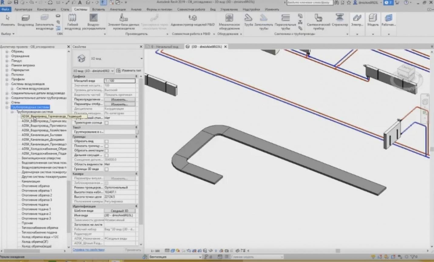
– Where is the “Utility System Types” classification specified? The utility system types are specified in the families. We can go to the “Families” tab here, in the Project Browser, go down to the air duct system, unfold the list and see what system types are available (smoke removal, exhaust air, pressurization); there are the most essential systems that have been created; the same is true for the pipeline systems. We have much more aspects for the pipeline systems. We have hot water: feed, circulation, fire-fighting water supply system, etc. All these utility systems having the “ADSK” prefix are loaded from the standard template that can be downloaded from the Autodesk website. They are already provided there and can be used immediately.
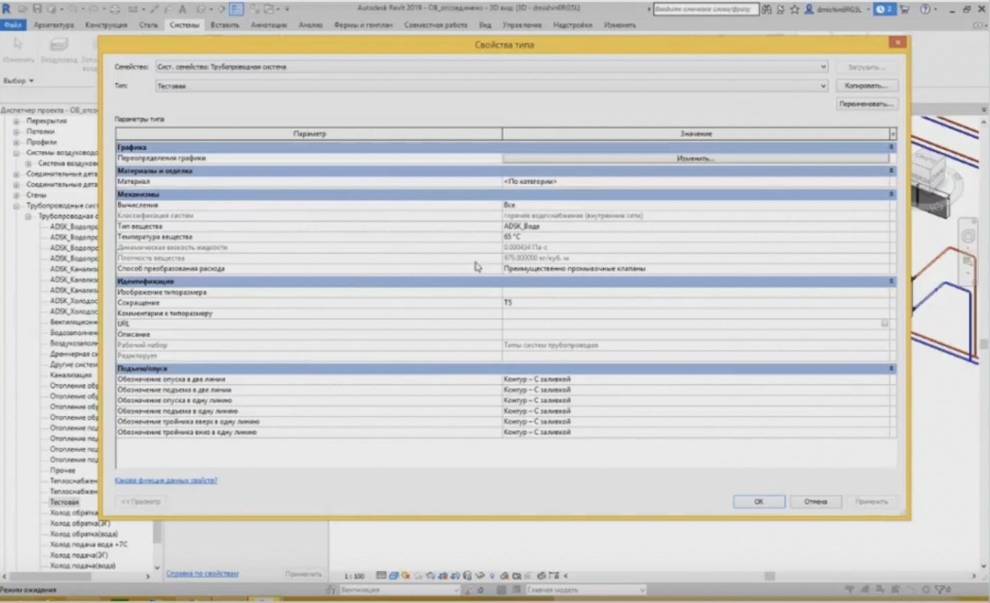
– If we need a new utility system, then by copying the existing one, we can give a new name to it, e.g., let's enter “Test”. First, in the settings, you may specify the abbreviation for the system, e.g., T5, and some characteristics of this utility system. Then, we can use the system we have just created as a utility system. When creating elements, e.g., a pipeline, I choose the type of the utility system from the list, i.e. “Test”. It has appeared and the abbreviation for the system is used, “T5”. The same is true for the air duct systems. I can also create a certain system and use it in my project.
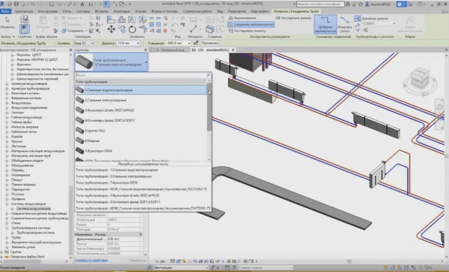
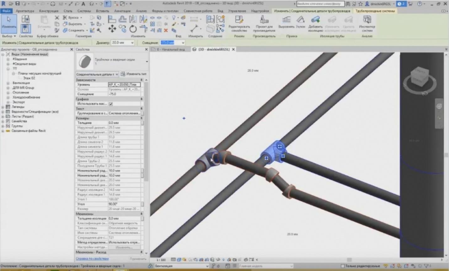
– Let's now see the configuration of the pipeline tracing. What do we have when we create the pipelines? When creating a pipeline, I can choose a particular pipe, and from the drop-down list, I can see that I have several different types, e.g., “ADSK_Polypropylene Sewage_Flared”, etc. How do they differ?
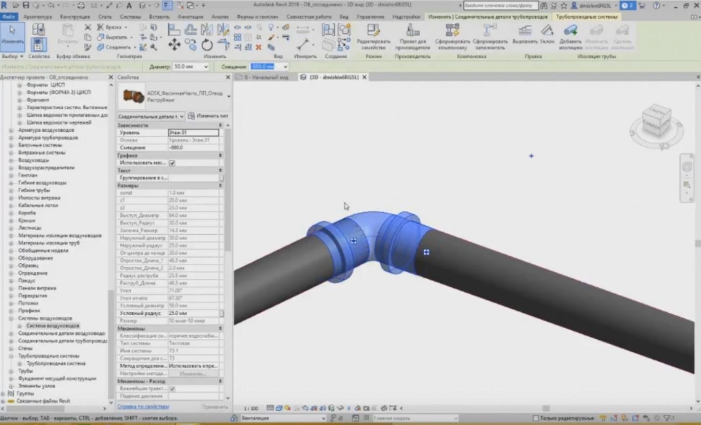
– If I choose a sewage pipeline, then upon creating this type of the pipe, the following connectors are created.
– If I need a T-shaped pipe joint, it will draw the joint of this type.
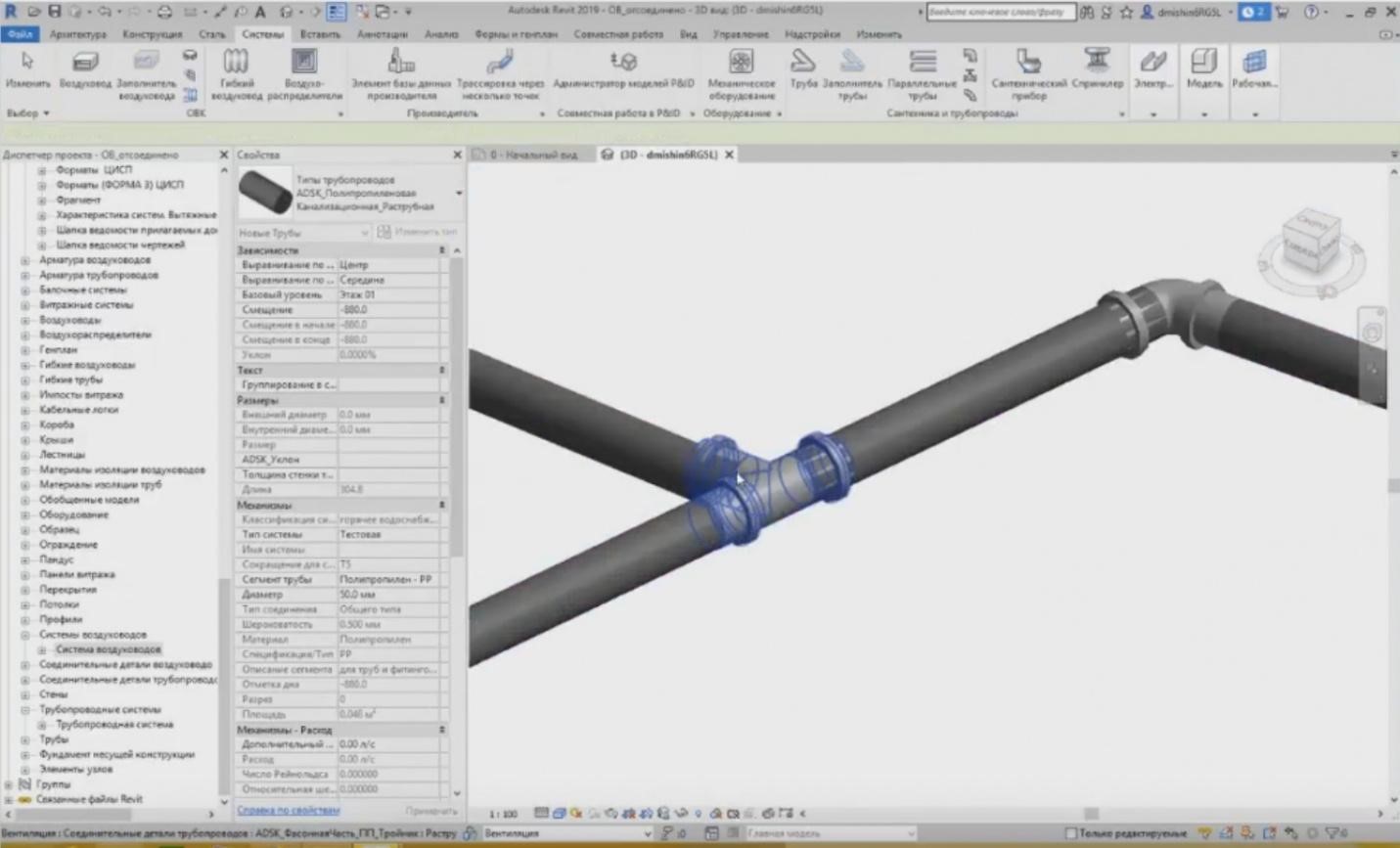
– If I choose the pipeline of another type, e.g., for steel water and gas supply pipeline, then in this case, completely different fittings are created. It looks a little bit skewed, because they are only drawn at 90º. You can see the difference in what fitting has been installed into a steel pipe and which of them was installed into a plastic flared-type pipe.
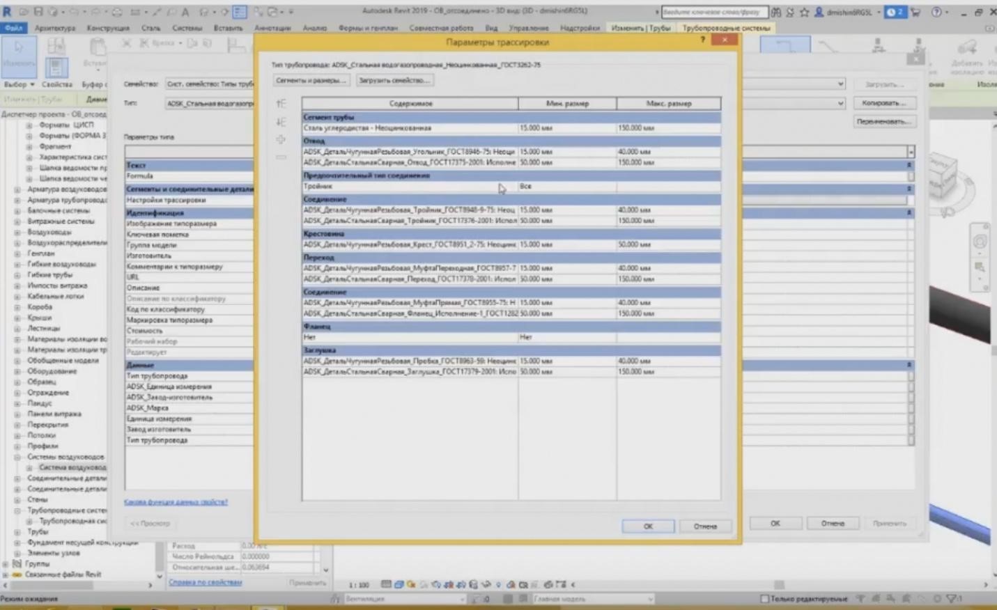
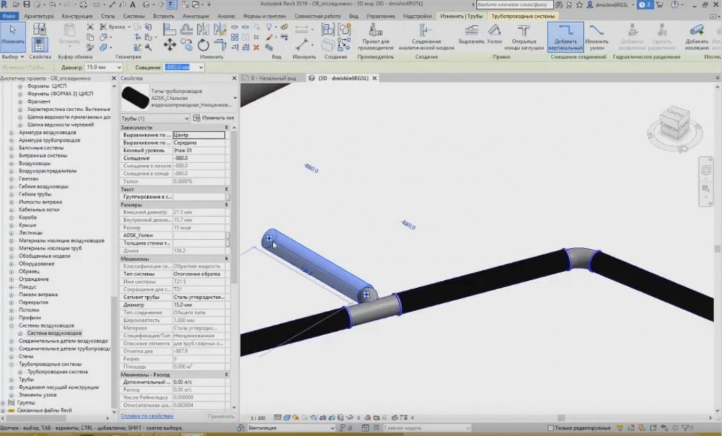
– All of these can be configured in tracings. If I choose the pipe and go to the properties of this pipeline, I will see the parameters for the tracing configuration. I press “Change” and I can see the list of connectors that will be used as connectors. I can see here, first, what pipe segment will be used: “Carbon Steel — Without Zinc Coating”, and the minimum and maximum dimensions that will be present in this pipeline system. After that, I can choose what fittings will be chosen, and I can set several options. For example, for the steel pipes, these can be the cast-iron threaded fittings that will be threaded on the steel, or for the welded connections, the steel channels are used. In the future, I can also choose the dimensions for a channel creation. For example, with 15 to 40 mm, I will have threaded connections, but with 50 to 150 mm, I will have welded connections.
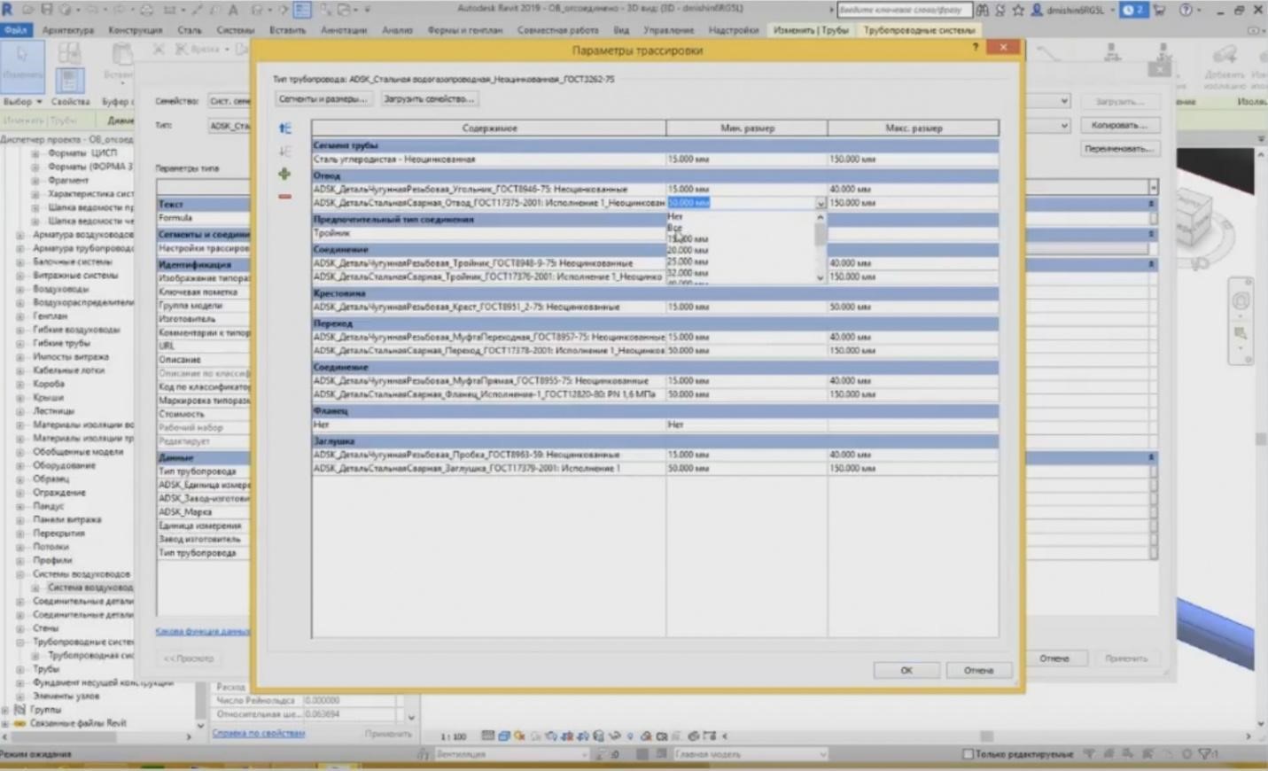
– Now, if I want to use a steel connector but not the cast-iron for some small diameters, then what should I do? I need to do the following: in the tracing settings I indicate that the welded steel fittings will be used for all dimensions.
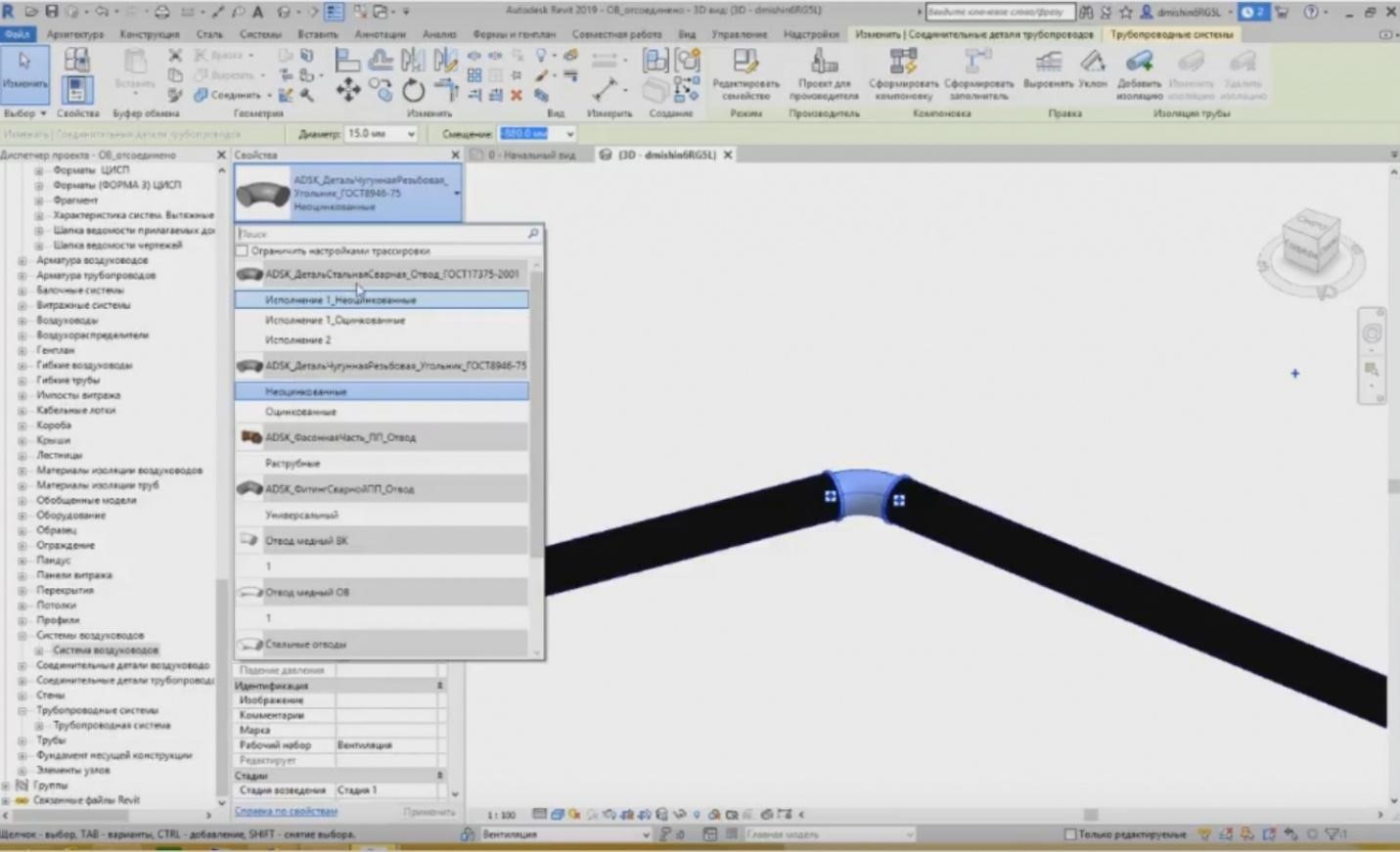
– Press OK, and then, when I highlight this fitting, I can easily change it to the steel fitting. It is “PartSteelWelded”. I choose this type, it has easily switched and changed the representation of the fitting.
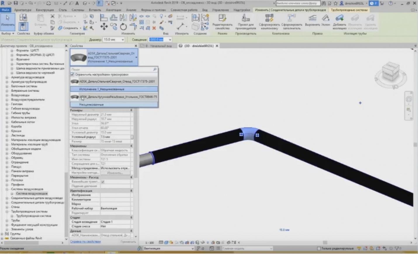
– All available fittings are shown in the list; all channels not only for the steel pipes, but you can also see plastic, copper, etc. It is troublesome to look for something in this large list; therefore, if your tracing settings contain only two types, then you can press the mark “Limit Tracing Settings”, and only the fitting types will be shown, which are specified in this settings, while others will not be shown here. And you can easily switch between them if you need to change the type. The same is true for the air ducts and power grids.
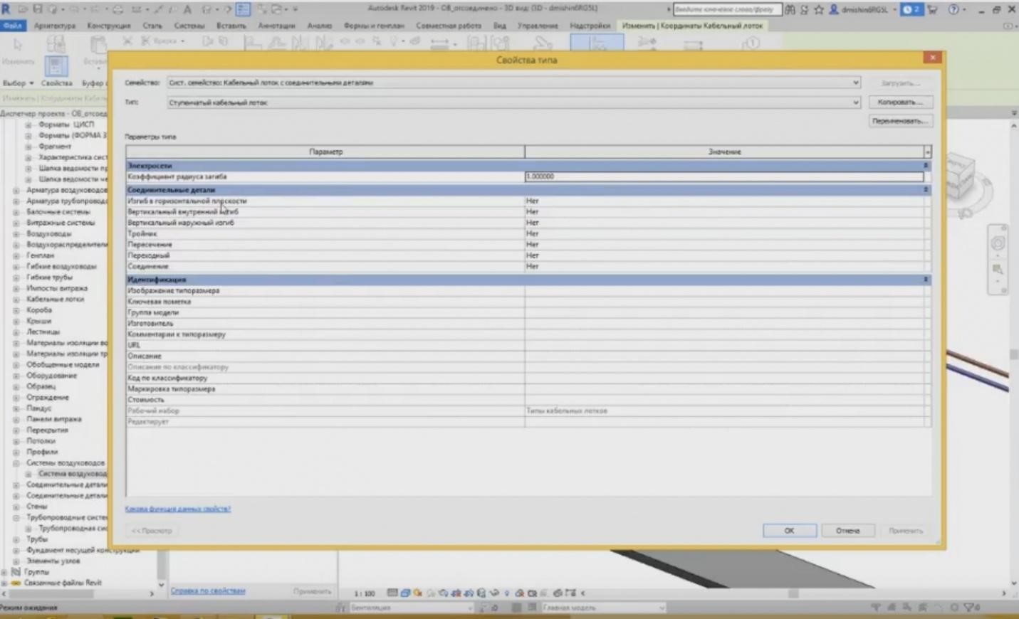
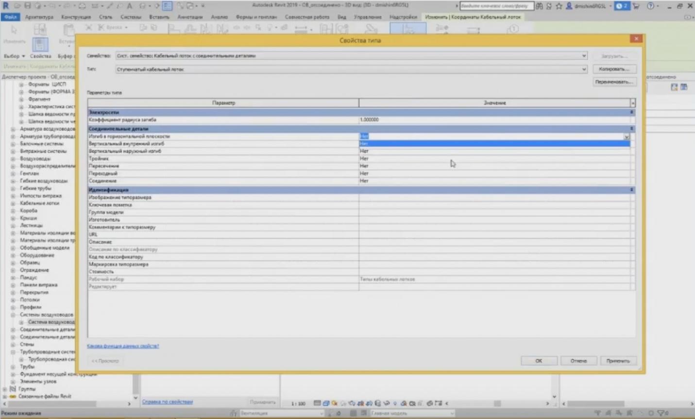
– Unfortunately, it is a little bit different with the power grids because the representation is provided a little bit differently. In the tracing settings, if I choose a stone tray, then I can see that there is no large “Change” button; the tracing settings are located right here. These are several positions: curvature, vertical inner and outer curvature, T-shaped pipe joint, crossing, etc. These are the positions that are also located in the tracing settings for the pipes and air ducts, but in a separate tab.
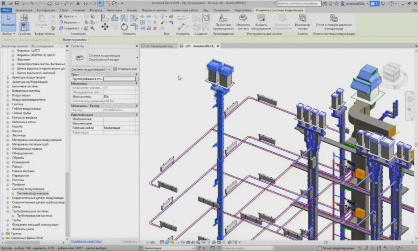
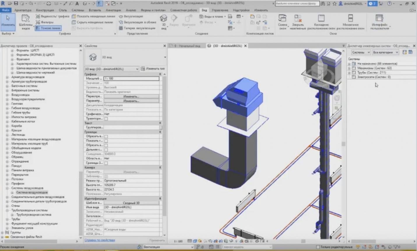
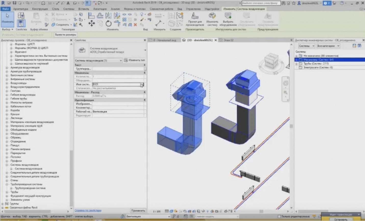
– Let's proceed. In some cases, air ducts can collect some loads. It makes the designer's work easier. How does it happen? For example, we have a pipeline system. The pipeline system can be highlighted using the “Tab” button. I have highlighted the air duct system, i.e. for the exhaust air. And I can see the name of the system, “V3k”, and the flow rate of the system, 575 m3/hr. How can it be defined?
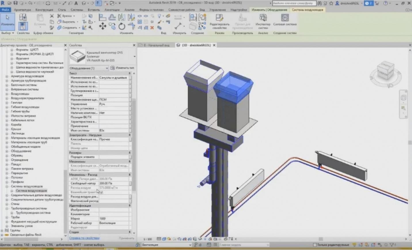
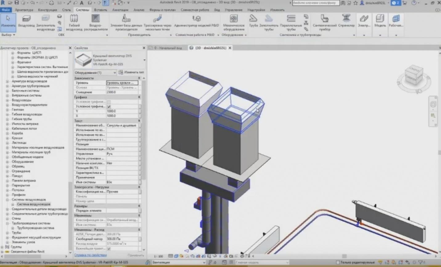
– For example, two roof fans are installed here; so, their flow rate is 575 m3/hr. And if I highlight certain pipelines, then the final flow rate is set at 575 m3/hr.
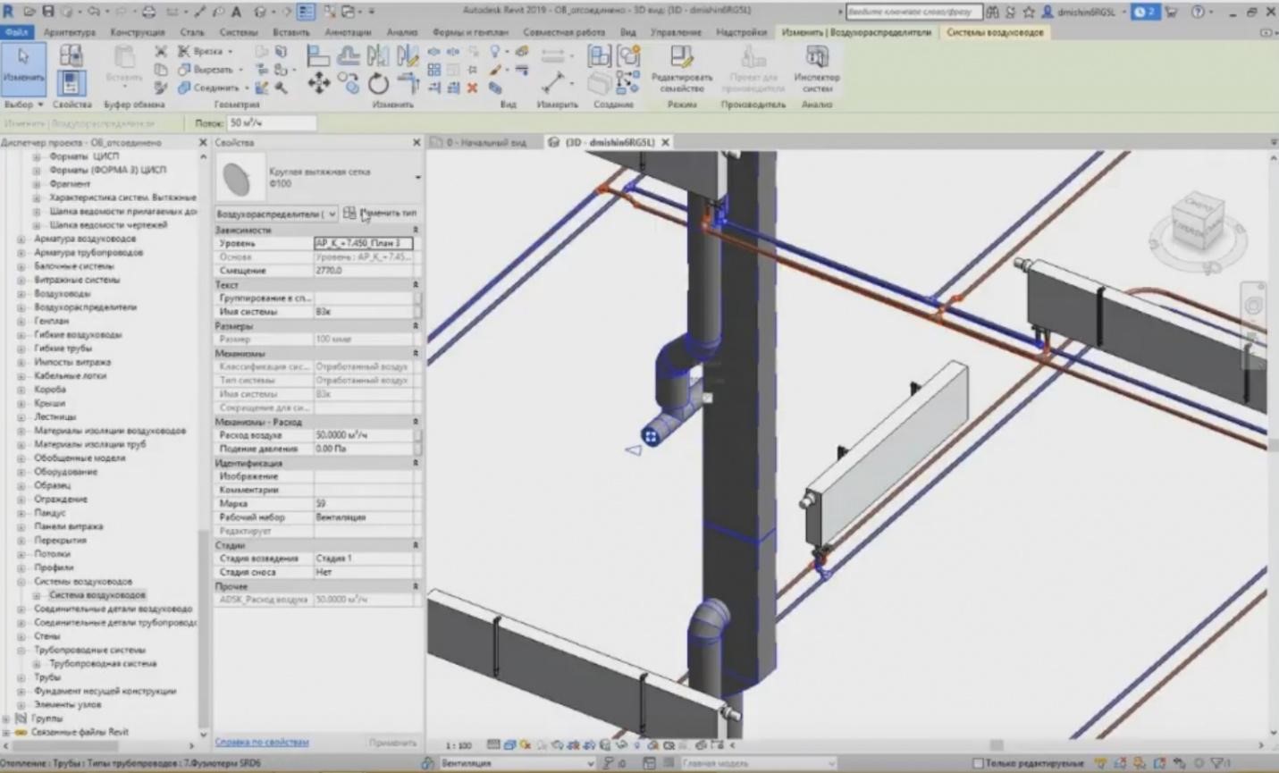
– How is it collected? It is collected using the equipment elements. For example, I have the exhaust circular grid, i.e. an air distributor, and its flow rate is shown here. I can set the flow rate for each air distributor, and in total, it will provide an output value here, on the top.
– If I change the flow rate in one location, e.g. I set 75 m3/hr instead of 50 m3/hr, then the flow rate for the entire system will change. So, if I choose the air duct here, I will see that the flow rate has become 600 m3/hr, i.e. it has increased. And then I need to replace these fans with the more powerful ones so that they would provide such flow rate, etc. The same can be done also for the utility systems of the pipelines. Moreover, we can set the water flow rate, but, unfortunately, it is a more complicated issue with the pipelines, especially with the sewage. It often happens that these sewage connectors depart in case of some changes in the utility systems, the connection between them is broken, and this flow rate is not taken into consideration. It is due to the fact that the sewage grids have an inclination, and when you set the inclination, a very complex geometry is created. It is very difficult to see in the large project that anything has broken somewhere. It takes much time, and the specifics is that the HVAC engineers do not make any calculations using this model. They calculate neither flow rates, nor pressures, nor some other parameters.
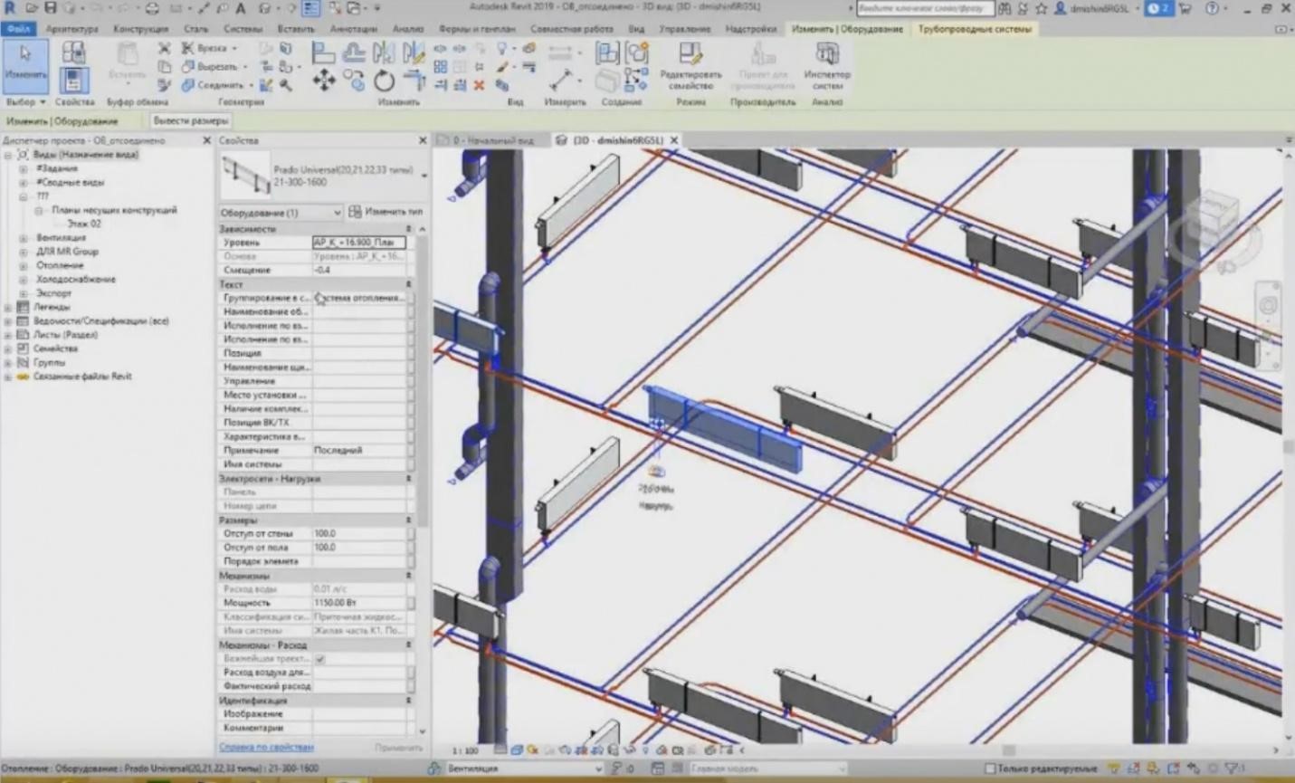
– In addition to what I have said before, we can set the equipment. The equipment is in a separate tab titled “Mechanical Equipment”, or we can set some sanitary devices, sprinklers, etc.
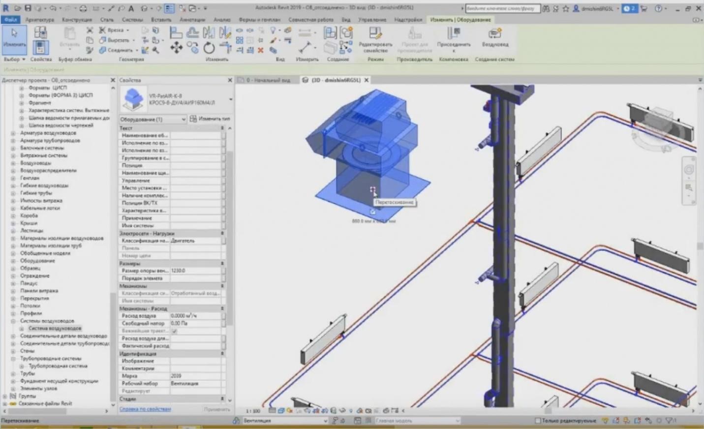
– What do we have when we set the mechanical equipment? Each piece of mechanical equipment has a particular connection. If I place it, then an icon for dragging and attaching this equipment to a particular utility system appears. Moreover, I can see the connection dimensions here, 860 mm x 860 mm. It is clear that these are the catalogue dimensions for this equipment and for attaching this equipment to the system. I can right-click on the icon and press the “Draw Air Duct” button.
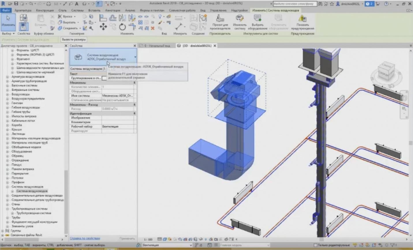
– Set a particular mark for it, e.g., set the offset of 3 meters. Thus, I have drawn such an air duct. As soon as I have drawn an air duct from this equipment, a particular system is also assigned to it. If I press “Tab” several times, I can choose the system; it is an exhaust air system. And Revit automatically suggests to use the name “ADSK Mechanisms_Exhaust Air1”. It just provides a name for the system “ADSK_Exhaust Air” and assigns sequential numbers 1, 2, 3, 4, 5, etc.
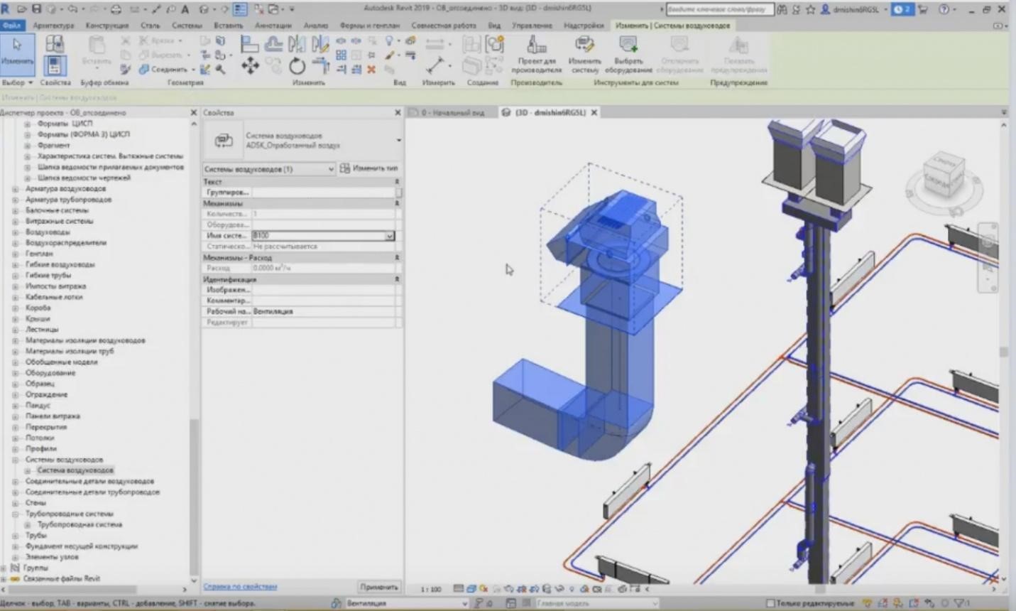
– You can change the name at any point so that the system names would not repeat. I can use “V100” because there is no such name yet. If the system already exists, then Revit will issue an error. For example, “V3k” already exists. Press Enter. Revit will say that “V3k” name is already in use”, and you cannot use it again. As soon as I have created even a small new system, I can see this utility system in the MEP System Browser. This is a new window in addition to the properties and the Project Browser. This window may be opened in the “View” tab, “User Interface”; tick the mark “MEP System Browser”.
– In the MEP System Browser, we can see all systems used in the project. So, we have a mechanism system now, i.e. pipelines, but we have no power grids here. Where did the “V100” system appear?
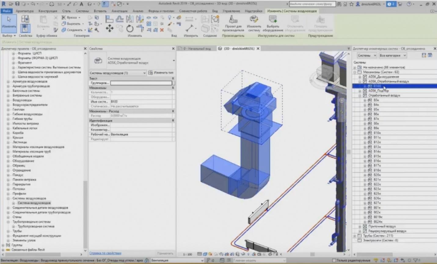
– This is a system of the exhaust air; so, we open the list, and we can see it in “ADSK_Exhaust Air”. We can see what equipment is used in the system, we can highlight it and we can show it in the project this way. Let me continue.
– In addition to the utility systems: ventilation, heating, and pipelines, we also have the utility systems for the power grids. The utility systems of the power grids are created in a similar way. We also set the tracing configuration as I have shown above.
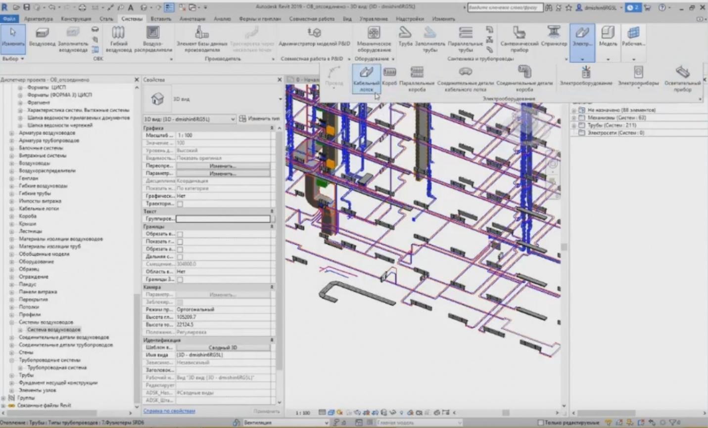
– In addition to this, we can also create the electrical equipment, the illuminating devices, and the electrical equipment. When we set the electrical equipment, unfortunately, we cannot do it now; the electrical equipment families are not loaded; we can set circuitry. Create electrical circuits and add a particular equipment we need to each electrical circuit. The specific features of working with the power grids are that the cables and wires are not modelled in Revit separately. Only these elements, such as boxes, cable trays, and the equipment itself are modelled; and there is also the “Wire” button, but you can see that it is disabled. Why is it disabled? It is only enabled when we are in the planar drawing, e.g., in a floor plan.
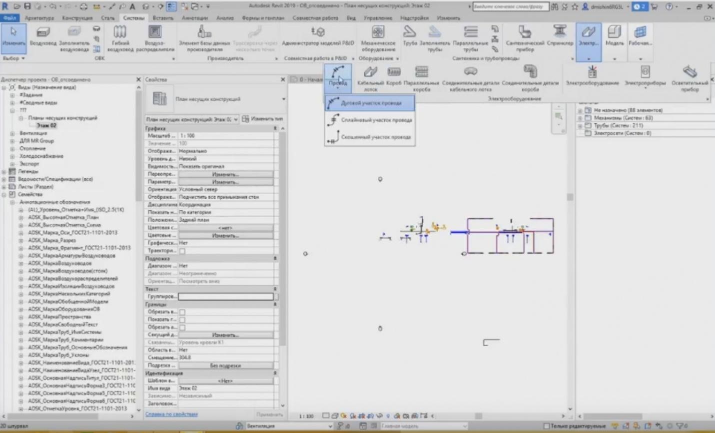
– If I go to the floor plan, the wire will become enabled. This is just a common annotation. I can draw it anywhere and in any form.
– For example, I can do it like this. You only need it for stylizing. The wire is not modelled. The cable length is calculated relative to the installed equipment, and it is calculated from the triangle with the maximum length between the equipment. Revit does it automatically.
– Unfortunately, I cannot load the project with the electrical equipment now. A problem occurred, so that is it for this step. Please ask your questions. There are many of them in the “Questions” tab, but I have not read any of them yet.
Questions and answers
– The first question from Ilya: “Can we see and download the projects?”
– Unfortunately, you cannot download them as they are for demonstrating purposes only. I think you can find some solutions to study over the Internet, even in Autodesk, when you install Revit, there are such test projects.
– “Do they plan to add communication systems?” Concerning the communication systems, if I have understood you correctly; Vladlen, what systems are you talking about?”
– Please clarify, Vladlen, and we will return to this question later.
– “Do pipe and air duct fittings belong to the system families or loadable families? Can we obtain them from the manufacturer?”
– The pipe and air duct fittings are loadable families. They are provided in the Autodesk template for heating, ventilation, water supply, and sewage. You can download it from the Autodesk website. In addition, some manufacturers also create their family libraries, and these can also be downloaded from the manufacturer's site.
– “We need a separate training for the electrical part in Revit. I think that the essential part of the webinar participants are electricians or people working with the electrical equipment”.
– Yes, sure, a separate training for the electrical part is an extensive subject; therefore, we need separate training courses for each section, for ventilation and heating, for water supply, sewage, or the electrical part. This is an extensive subject that requires at least 40 hours.
– Stanislav, I will add a comment separately from myself regarding the separate training course. Thank you for the comments. We will collect these comments and leave some notes for our future events. It is possible to plan the training course for the next year, because the events have already been scheduled for this year already. So, write please about your wishes regarding these issues.
– Andrey asks again: “If the cable is not shown in the model but only present in the form of annotation, how can we calculate the cable quantities?”
– I tell you once more that the cable is calculated relative to the equipment used in the project. If this equipment is connected in circuits, then Revit reads the cable length based on the position of this equipment for its maximum length. It means that it adds height, width, and length between these pieces of equipment in the system.
– Natalya asks: “Please detail how to assign a new name to the ventilation system? For example, when you copy the “V1” system, you will assign a new name to it, e.g., “V2”?”
– Let me show you. For example, I have created the system “V100”. When I copy the system and place it side by side and I need to create a new name, it assigns a new name for it immediately, because the names for different systems cannot be the same in Revit. Now, I can highlight the system. I double-click “Tab”. When I click it for the first time, all system elements are highlighted. When I click “Tab” for the second time, the system is highlighted. And here, in the settings, I can see the system name. The software has automatically named it “ADSK Mechanisms_Exhaust Air 1”, this is a standard scheme. And this time, I can delete the name and enter “V101” there.
– Dmitry Sokolov asks: “Tell me please, if the air flow rate in the mechanical ventilation before and after the ventilation is different, what settings do we need?”
– Generally, each type of equipment has its air flow rate. You can enter it manually, e.g., 500 m3/hr. It can also take the flow rate from the system. You can see that it is disabled now. It happens because the system itself does not provide this flow rate. The flow rate of 600 m3/hr is shown here. Probably, this flow rate is already set in the family. Unfortunately, I cannot answer this question right now. I have updated the air flow rate to 600 m3/hr, and here it has left the old flow rate of 575 m3/hr; probably I cannot answer this question right now. Let's proceed.
– Question from Evgeny: “What about calculations and single-line schemes? Does Revit produce them automatically?”
– Evgeny, single-line schemes are not used in Revit; you should either create them manually or use plug-ins. I cannot think right now of what plugins among those, which are publicly available, can do that.
– The next question from Vitaly: “What families for the electrical equipment are provided the best of all? Are there any good bases for downloading?”
– For now, Autodesk has not yet provided the templates for the electrical part. As far as I remember, they have provided the template with the electrical equipment families and a general template for the electrical part. In addition to this, some training centers provide these libraries during the training course or with the template. Besides, different manufacturers already create the libraries containing their equipment. So, the library is also created by the designers. If a company works with Revit and produces all documents in Revit, they have their library. But they, of course, will not give it to you and other people because it took much effort to create them.
– Aleksey asks: “Does the expert board accept BIM projects? What about the axonometric projections in Revit?”
– The axonometry is fine in Revit. Eou can see that in any 3D view as this is axonometry. You may stylize it and create some 3D nodes for better understanding of what happens there. It is seen especially well if we create, for example, composite views, wherein we have several different systems to view the settings; how it is all connected there. This is the first point. And the second is that the expert board accepts the BIM projects, but, certainly, it accepts them in addition to the primary documentation, the planar drawings. But BIM modelling is only an emerging area, although we already have such practice. Some projects have been provided to the expert boards not only as planar documents but also in the form of a BIM model that was reviewed by the experts to close some comments by just looking at the model.
– “Can Revit print out the project data?”
– It depends on the data. Of course, you can print drawings, you can print them in PDF or send them to the printer. You can export them in AutoCAD.
– I will answer Alexander's question. I will tell you once more that there will be a record. It will be prepared within several days after the webinar. We will publish it on the website and after that distribute among the participants registered for the webinar. You will receive a link to the e-mail and you will be able to watch it. Moreover, you can also watch records of the previous webinars. Let me remind you that it is the fifth webinar of the series, i.e. all of five webinars have already been published on the website and you may watch the one you need. Yes, I have duplicated the Alexander's question about the possibility to print data. Are there any more questions? We have two more minutes. We can answer another question, and there is also a comment here: the questions we could not answer today may be sent to our e-mail; I will send it to the chat. If possible, we will clarify the information from Stanislav and write an answer to you. E-mail info@zandz.ru. If you have any questions, then write and we will try to answer them right now. The e-mail is in the chat.
– “Can you consult on the family and its creation?”
– Anastasia, this is possible, but there are training courses for the creation of families in some training centers and it is provided there. You can have a training course there so that not to do that by yourself. I think that in this case, the progress will be much better.
– “When are the separate subjects of the electrical part, heating, and ventilation planned for?”
– I have already told you earlier that we are planning the next webinars starting from the next year, because the schedule for this year is already composed and all the webinars have been already scheduled. Therefore, in the beginning of the next year, a new list of webinars will be created, and it is likely that some of these narrow subjects will be included. All the current webinars announced on the website are sent to the chat.
– I cannot see any more questions. Looks like there are no questions anymore. I think it is time to finish. Thank you for the participation. Visit our next webinar.
– Yes, thank you! Anatoly, thank you, too. Goodbye to everyone!
<< Previous page
slides from 1 to 2
Related Articles:
