Statutory requirements
Considering the grounding of lightning conductors, we again have to omit the standards of the IS 153-34. 21. 122-2003, which do not express any specific conditions or requirements. Form AD 34. 21. 122-87 regulates the regulatory requirements of grounding without penetrating the essence of the issue, and they only concern the design features of grounding facilities, rather than the level of ground resistance. For example, for isolated lightning protection structures, AD 34.21.122-87 describes the arrangement of foundation bases and the construction of a special ground electrode. The intervals between the rod electrodes of the ground electrode and the depth of vertical immersion of the electrodes are shown in Figure 1.
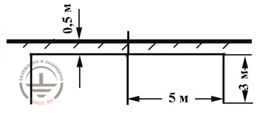
Figure 1. Minimum parameters of the ground electrode from the tape and three vertical rod electrodes along the AD 34.21.122-87*
The form does not express any requirements for changing the dimensions of the rod electrodes in accordance with the specific resistance of the soil. It remains to be assumed that the authors of the form consider the design of a special ground electrode and the overall dimensions of its elements suitable for all types of soils. Dynamics of growth of ground resistance of Rgr construction is shown in the linear chart of Fig. 2.
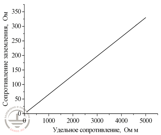
Figure 2. The value of the grounding resistance of a typical ground electrode from AD 34.21.122-87*
The standard of the company "Transneft" includes, in particular, a chart with the standardized data of grounding resistance of lightning-conductor structures (Table 1). The table contains the values of ground impedances for supports of overhead power lines with a design voltage of at least 110 kV. The authors of the Standard numerically copied the tabular data from the latest edition of the code of regulations of the Electrical Installations Code (EIC). On the one hand, the rigid norms of the Rules are quite understandable. Resistance of grounding of supports of overhead power lines significantly influences the level of atmospheric overvoltage in the elements of linear electrical insulation. On the other hand, the motivation for the distribution of standards to grounding structures of lightning arresters is questionable and incomprehensible. In the conditions of high ohmic soil, it is impossible to realize the requirements of the Rules by reasonable and justified design solutions. In support of the foregoing, Figure 3 shows the calculation of the grounding structure of the lightning rod, the assembly of which seems to be at least unrealistic, and, as a maximum, fantastic. The structure is mounted in the form of a square structure. The magnitude of the side of the square is indicated along the abscissa. The calculation is given for two initial modifications - with immersion in the soil to 3 and 10 meters. Based on the tabulated data, the soil resistance in the range of 5,000 Ohm * m corresponds to a normalized value of 30 Ohm. The graph shows that at the grounding resistance of 30 ohms (R3/ρ = 0.006 m-1) and ρ=5 000 Ohm, the adjoining territory of the lightning storm foundation must be filled with metal on a plot of 50x50 meters. Under the same conditions, in order to achieve an optimum grounding resistance, a horizontally located bus with a length of half a kilometer or more will be required.
|
Equivalent resistivity |
The maximum allowable ground resistance of the support |
|
Up to 100 |
10 |
|
More than 100 to 500 |
15 |
|
More than 500 to 1000 |
20 |
|
Over 1000 to 5000 |
30 |
|
Over 500 |
6*10-3 |
Chart 1*
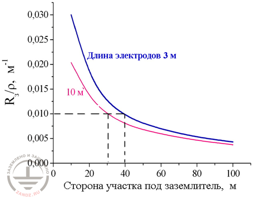
Figure 3. To assess the feasibility of fulfilling the requirements of the OJSC "Transneft" standard with the help of concentrated grounding*
Taking into account the complexity of manufacturing such a grounding resistance, the Standard foresees chemical treatment of the soil at the installation site or a partial replacement of the soil volume.
To estimate the scope of the proposed work, let's consider the standard situation using a grounding hemispherical electrode. The potential of the hemispherical electrode (Fig. 4), located in a two-layer soil massif (regardless of the method of preliminary soil preparation-chemical treatment or partial replacement of a certain segment), is calculated by the formula:
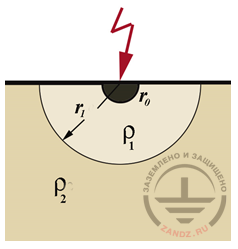
Figure 4. Potential of hemispherical electrode in two-layer soil*
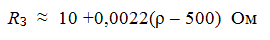
Based on this, the exact grounding resistance is calculated using the formula:
Ideally, when a partial replacement of the soil volume or its chemical treatment proved to be extremely effective and reduced the specific resistance of the ground massif to zero, the ground resistance:

This formula allows us to measure the radius r1 of the processed area of the massif, which in our case is about 40 meters, which is equivalent to the volume of the ground mass of 134,000 m3. The obtained value of the volume of soil, which must be processed, indicates the unreality (or inexpediency) of the planned event.
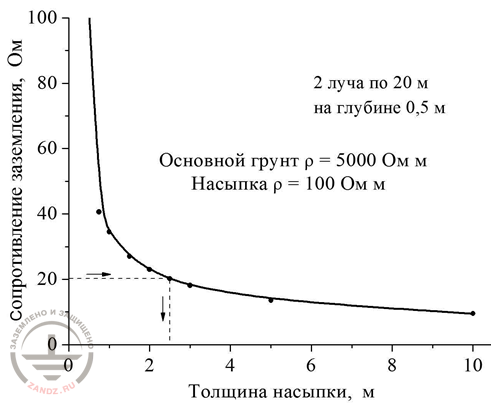
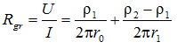
Figure 5. The ratio of the ground resistance of a double-beam horizontal ground electrode to the thickness of the soil layer*
Similar results are obtained when evaluating measures using other electrode configurations. For example, let's consider a two-beam grounding structure with horizontally arranged buses. The length of each bus is 20 meters. The hyperbolic dependence in Fig. 5 captures the decrease in the ground resistance with a variable variation in the thickness of the surface soil layer with low resistance. The normalized resistance of 20 Ohm is achieved by chemical treatment (or replacement) of the upper soil massif to the depth of 2.5 meters. It is important to understand at what distance from the grounding structure it is possible to complete the chemical treatment of the soil. The potential in the outer plane of the soil massif U(r) helps here. The boundary processing zone is the line beyond which the potential in the outer layer of the soil massif U(r) is significantly lower than the potential of the ground electrode UЗ = U(r0).
Figure 6. Graph of potential reduction at the ground surface in a single-layer and two-layer soil*
However, there are no serious reasons for optimism here. According to the graph presented in Figure 6, we see that in a soil massif of two layers the potential decreases much more inertly than in a single-layered soil with a uniform composition.
In our case, the potential of the upper soil layer is kept within 0.3 Ur0) even at a hundred-meter distance from the grounding structure. Chemical treatment of soil, and moreover, a partial replacement of the volume of soil under such conditions, seem excessively expensive. Similar research results suggest that the theoretical and practical principles of grounding of lightning rods need to be approached more rationally and pragmatically, while clearly understanding the feasibility of reducing the resistance of the grounding structure.
Why should I ground the lightning rod?
The subtitle of this section can hardly be called trivial. Since the day of the invention of lightning rods, they are connected to ground contours. In another way, there is no other way of lightning rods to take lightning current into the ground. According to the rules for the installation of electrical installations, rationing of ground resistance is carried out to increase the safety of lightning current drainage to the ground. A reasonable comment arises immediately: why are we talking about danger or security? Once again, let's get back to the power lines that are laid through the air. In this system, the grounding resistance of overhead power lines directly affects the level of atmospheric overvoltage in a garland of electrical insulators.
As for the construction of lightning rods, the situation is opposite here. Lightning rod easily develops the potential of electrode grounding. The ultimate grounding resistance in no way affects the ability of the lightning rod to attract a lightning discharge. In laboratory conditions, the specialists repeatedly tried to establish a connection between the ability of lightning-conductor structures to attract the discharge and grounding resistance. The attempts were futile. There is an obvious explanation for this, it is only necessary to pay attention to the behavior of lightning. Lightning never strikes a lightning rod itself. The counter discharge, if to be specific - its plasma channel, attracts a lightning branch. The counter discharge rushes from the lightning rod to the lightning in the electromagnetic field of thunderclouds. The development of the plasma channel (the so-called counter leader) occurs only at the current of several tens of amperes. If we compare the lightning potential of 107-108 V, which it carries from thunderstorm clouds, the decrease in the voltage at the resistance of the grounding contours of the lightning rod plays an insignificant role. With a resistance on the ground contour of 10, 20, 50, or 150 ohms, the voltage from the 10 ampere current will hardly exceed the threshold of 104 V. Compared to a hundred million volts of lightning, this voltage is negligible.
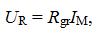
As we know, the main task of a separate lightning rod is to prevent lightning from entering the protected object, thereby preventing the discharge from spreading over the metal elements of the structure. To solve the task, the distance between the protected complex and the lightning rod is rigidly rationed. This concerns both air atmosphere and the surface of the ground. Suppose that the air and ground intervals between the structure and the lightning rod are correctly selected and exactly observed. But even in this situation, a significant fraction of the lightning current enters the ground contour of the protected structure. This is especially true when the function of the ground electrode is performed by the reinforced concrete foundation of the protected structure with the increased geometry of the sides. The line graph data in Figure 7 show the magnitude of the fraction of the lightning current that penetrates into the ground contour of the protected structure. The value of penetration depends on the interval between the grounding contours of the lightning rod and the protected structure.
The arrangement of the lightning rod ground electrode presents itself a horizontal strip (10 meters long) with three electrode rods, each of which is three meters long. The foundation of the complex has a square geometry of 50x50 meters, the level of penetration is three meters. For a computer study, a situation is simulated where the top layer of a homogeneous ground massif is replaced by a highly conductive composition 2.5 m deep, the resistivity of which is 50 times lower than the resistance of the main ground. The standard of JSC "Transneft" regulates the distance between the protected structure and the lightning rod, which is five meters. Such an isolation interval is not an obstacle to the penetration of the lightning current from the grounding of the lightning rod to the grounding of the structure, especially if the soil area around the lightning rod is replaced or chemically treated. The standard of JSC "Gazprom" regulates the insulation interval of 15 meters. But even at such intervals, the share of lightning current entering the ground contour of the protected structure is more than 50%.
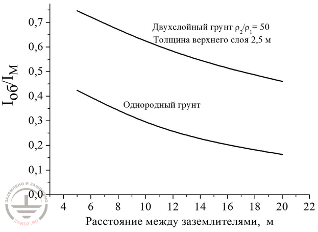
Figure 7. The magnitude of the lightning current that has entered the grounding contour of the object through the grounding of the lightning rod in relation to the distance between them*
Again, there is doubt about the feasibility of lowering the grounding resistance. In the forefront of this issue, two aspects remain unsettled: step voltage and the formation of spark channels. As for the formation of spark channels, this topic will be disclosed in a separate section of the research. Regarding the step voltage, it is obvious that it directly depends both on the structural features of the grounding contour of the lightning rod and on the contour impedance of the grounding. The function in graph 8 shows the dynamics of eduction of step voltage when removed from the grounding contour of the lightning rod.
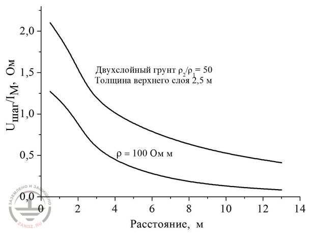
Figure 8. The dynamics of reducing step voltage*
The replacement of a homogeneous ground massif with a highly conducting low-ohmic composition to the depth of 2.5 meters is theoretically effective. In the area adjacent to the lightning rod, the step voltage exceeds this parameter by more than two times. However, in practice, the analysis of absolute values in a 10-meter distance from the grounding structure shows Ustep/IM≈0.5. Thiscertifies that the lightning current with the amplitude of 100 kV forms a step voltage, no less than 50 kV! Such a voltage cannot be considered safe for people close to the grounding contour. And again, it is impossible to find any recommendations on the permissible value of the step voltage for spreading a lightning current in any normative document. The next question on the topic of effective and safe lightning protection of oil and gas facilities remains unanswered.
How to calculate the grounding contour?
In this subsection, we again address to the possibility of meeting regulatory requirements with reasonable financing of safety measures. The effectiveness of the lightning protection means is practically independent of the resistance level of the grounding means. Increased or reduced ground resistance is in no way related to the degree of destruction caused by a lightning discharge in the territory of processing facilities or in a tank farm. Therefore it is very tempting to try to comply with the normative requirements of the Standards without costly measures to partially replace the volume of the soil massif or chemical soil cultivation.
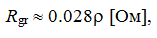
It is advisable to arrange grounding contours for each isolated lightning rod only in low-resistance soils, in which even the simplest grounding contours, regulated by the form AD 34. 21. 122-87, show themselves to be capable. For example, the specified Instruction recommends the use of a horizontally located bus with the length of 12 meters and three vertical ground rods with a length of five meters. The resistance of the grounding contour in a soil massif with specific resistance ρ is calculated by the formula:
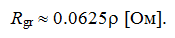
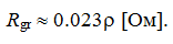
With a soil resistivity of not more than 300 Ω*m, the resistance of the grounding contour does not exceed Rgr = 0,0625*300=18,75 Ohm*m. In soils with the increased resistance, four buses of 20 meters long, which are located in relation to each other at an angle of 90° are used. In this case, the resistance of the grounding contour is equal to
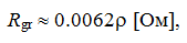
and installation of the five-meter vertical grounding rods at the ends of each bus reduces the ground resistance to the level:
The problems arise when the grounding contour is mounted in soils with a resistivity of 1,000 Ω*m or more. In this case, the idea of assembling a single grounding structure, to which isolated lightning rods are connected, deserves attention. Let's take a look at figure 9, which presents lightning protection of the tank park with three hundred-meter ground wires, with an intermediate interval between the lines of 50 meters.
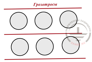
Figure 9. Cable protection of a group of tanks*
The combination of lightning protection wires with horizontally arranged buses forms a grounding contour of two cells. The size of each cell is 50x100 meters. The resistance of the grounding structure with horizontal beam laying to the depth of 0.7 meters is:
Thus, the combined grounding contour is able to solve the tasks in soils with the resistance of 1 000-3 000 Ohm*m, observing the regulatory requirements of JSC "Gazprom".
It is important to emphasize that the equipping of each of the isolated lightning rod with local ground electrodes does not affect the resistance level of the combined grounding contour. For example, if you use a lightning rod foundation support as a local ground electrode (the length of the support armature is five meters, the radius is 0.2 meters, Rgr = 0.1 ρ), then the total resistance of the combined grounding contour of six lightning rods, including six such supports, is reduced by no more than 6%. The explanation for this is very simple - effective shielding of rods by horizontally arranged buses. Increasing the length of the buses and connecting lightning protection supports by them, it is quite possible to reduce the resistance of the grounding contour to 20 ohms in high-resistance ground massifs with the resistance up to 5,000 Ohm*m.
Experts can refute this idea by remarking on the inductance of the bus. The longer the bus is, the more inductive it is, and the more inertly it participates in spreading of the impulse current. Such a remark is quite competent. Nevertheless, two facts speak in favor of the idea proposed above. First, none of the mentioned forms establishes any regulatory restrictions on the impulse resistance of grounding. Secondly, in soils with increased resistivity, the impulse current enters the grounding bus at a high speed. Therefore, the ground resistance Rgr(t) = Ugr(t)/iM(t) shows the values that meet the requirements of the standards. Figure 10 shows the dynamic variation of the ground resistance values for a horizontal bus located between the lightning protection supports. The length of the bus is 200 meters, the specific resistance of the soil massif is 5,000 Ohm*m, the relative dielectric permittivity of the soil is 5. Consideration of dielectric permeability is important in case when the capacitive leakage into the soil is equated to conductive.
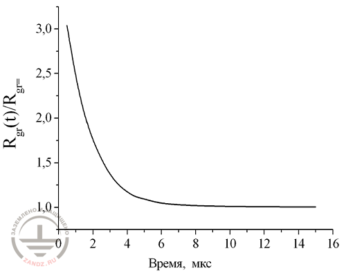
Figure 10. Reducing the ground resistance of a horizontal bus that is 200 m long*
On the graph, it is easy to see that even after 5-6 μs the ground resistance decreases almost to stetionary values. Thus, we come to the next conclusion: in comparison with the partial replacement of the volume of a soil massif of 800-1,000 m, laying of horizontal buses 800-1,000 m long is more expedient and more profitable. Will the implementation of the above-mentioned measures lead to an increase in the effectiveness of lightning protection structures and the safety of employees in the protection zone - the question remains open.
* - illustrations are taken from the article of prof. E.M.Bazelyan "Lightning protection of oil and gas facilities"
See also:
- Webinars with the leading industry experts
- Everything for the calculation of grounding and lightning protection
- Useful materials: articles, recommendations, examples
Related Articles:

 Protection of Fuel and Lubricant Materials (FLM) Storages with Floating Roofs Against the Static Electricity
 Five Most Dangerous Effects of Lightning